
User Manual
Page 12
... a Processor 3 Installing DDR4 memory 4 Connecting the Front Panel Header 5 Installing the Motherboard 6 Connecting the Power Connectors 7 Installing SATA Drives 8 Installing a Graphics Card 9 Connecting Peripheral Devices 10 Power On...11 Specifications...14 Package contents 18 Block Diagram ...19 Rear I/O Panel...20 LAN Port LED Status Table 20 Realtek Audio Console 20 Overview of Components 22 CPU Socket...24 DIMM Slots...25 PCI_E1~3: PCIe Expansion Slots 26 SATA1~4: SATA 6Gb/s Connectors 26 M2_1~2: M.2 Slots (Key M 27 JFP1, JFP2: Front Panel Connectors 29 JCOM1: Serial Port...
... a Processor 3 Installing DDR4 memory 4 Connecting the Front Panel Header 5 Installing the Motherboard 6 Connecting the Power Connectors 7 Installing SATA Drives 8 Installing a Graphics Card 9 Connecting Peripheral Devices 10 Power On...11 Specifications...14 Package contents 18 Block Diagram ...19 Rear I/O Panel...20 LAN Port LED Status Table 20 Realtek Audio Console 20 Overview of Components 22 CPU Socket...24 DIMM Slots...25 PCI_E1~3: PCIe Expansion Slots 26 SATA1~4: SATA 6Gb/s Connectors 26 M2_1~2: M.2 Slots (Key M 27 JFP1, JFP2: Front Panel Connectors 29 JCOM1: Serial Port...

User Manual
Page 13
... Windows® 10 39 Installing Drivers 39 Installing Utilities 39 UEFI BIOS...40 BIOS Setup...41 Entering BIOS Setup 41 Resetting BIOS...42 Updating BIOS...42 EZ Mode...44 Advanced Mode ...47 SETTINGS Menu...48 OC Menu...51 M-FLASH Menu...55 OC PROFILE Menu 56 HARDWARE MONITOR Menu 57 RAID Configuration 59 Enabling Intel® Rapid Storage Technology 59 Creating RAID Volume 60 Removing a RAID Volume 61 Resetting Disks to Non-RAID 62 Rebuilding RAID Array 63 Installing RAID Driver 64 Installing Intel® Rapid Storage Technology Software 64 Intel® Optane™ Memory...
... Windows® 10 39 Installing Drivers 39 Installing Utilities 39 UEFI BIOS...40 BIOS Setup...41 Entering BIOS Setup 41 Resetting BIOS...42 Updating BIOS...42 EZ Mode...44 Advanced Mode ...47 SETTINGS Menu...48 OC Menu...51 M-FLASH Menu...55 OC PROFILE Menu 56 HARDWARE MONITOR Menu 57 RAID Configuration 59 Enabling Intel® Rapid Storage Technology 59 Creating RAID Volume 60 Removing a RAID Volume 61 Resetting Disks to Non-RAID 62 Rebuilding RAID Array 63 Installing RAID Driver 64 Installing Intel® Rapid Storage Technology Software 64 Intel® Optane™ Memory...
User Manual
Page 14
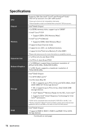
...-2666 Memory (Max.) ∙∙Supports Dual-Channel mode ∙∙Supports non-ECC, un-buffered memory ∙∙Supports Intel® Extreme Memory Profile (XMP) *Please refer www.msi.com for more information on next page 14 Specifications Intel® B460 Chipset ∙∙Supports RAID 0, RAID 1, RAID 5 and RAID 10 for Intel Core™ processors * SATA1 will be unavailable when installing M.2 SATA SSD in the M2_1 slot. ** Before using the F SKU processors. Specifications CPU Chipset Memory Expansion Slot Onboard Graphics Storage RAID Supports...
...-2666 Memory (Max.) ∙∙Supports Dual-Channel mode ∙∙Supports non-ECC, un-buffered memory ∙∙Supports Intel® Extreme Memory Profile (XMP) *Please refer www.msi.com for more information on next page 14 Specifications Intel® B460 Chipset ∙∙Supports RAID 0, RAID 1, RAID 5 and RAID 10 for Intel Core™ processors * SATA1 will be unavailable when installing M.2 SATA SSD in the M2_1 slot. ** Before using the F SKU processors. Specifications CPU Chipset Memory Expansion Slot Onboard Graphics Storage RAID Supports...

User Manual
Page 15
... power connector ∙∙4x SATA 6Gb/s connectors ∙∙1x USB 3.2 Gen 1 5Gbps connector (support additional 2 USB 3.2 Gen 1 5Gbps ports) ∙∙2x USB 2.0 connectors (support additional 4 USB 2.0 ports) ∙∙1x 4-pin CPU fan connector ∙∙1x 4-pin water pump connector ∙∙2x 4-pin system fan connectors ∙∙1x front panel audio connector ∙∙2x system panel connectors ∙∙1x parallel port connector ∙∙1x serial port connector ∙∙1x Chassis Intrusion connector ∙∙1x Clear CMOS jumper...
... power connector ∙∙4x SATA 6Gb/s connectors ∙∙1x USB 3.2 Gen 1 5Gbps connector (support additional 2 USB 3.2 Gen 1 5Gbps ports) ∙∙2x USB 2.0 connectors (support additional 4 USB 2.0 ports) ∙∙1x 4-pin CPU fan connector ∙∙1x 4-pin water pump connector ∙∙2x 4-pin system fan connectors ∙∙1x front panel audio connector ∙∙2x system panel connectors ∙∙1x parallel port connector ∙∙1x serial port connector ∙∙1x Chassis Intrusion connector ∙∙1x Clear CMOS jumper...

User Manual
Page 18
Package contents Please check the contents of the above items are damaged or missing, please contact your motherboard package. It should contain: Motherboard MAG B460M BAZOOKA User manual 1 Documentation Case stand-off notification 1 Quick installation guide 1 Application Driver DVD 1 Cables SATA 6G cables (2 cables/pack) 1 Case badge 1 Accessories Product registration card 1 M.2 screws (3 pcs./pack) 1 ⚠⚠Important If any of your retailer. 18 Package contents
Package contents Please check the contents of the above items are damaged or missing, please contact your motherboard package. It should contain: Motherboard MAG B460M BAZOOKA User manual 1 Documentation Case stand-off notification 1 Quick installation guide 1 Application Driver DVD 1 Cables SATA 6G cables (2 cables/pack) 1 Case badge 1 Accessories Product registration card 1 M.2 screws (3 pcs./pack) 1 ⚠⚠Important If any of your retailer. 18 Package contents

User Manual
Page 35
...# 20 Ground 21 BUSY 22 Ground 23 PE 24 Ground 25 SLCT 26 No Pin Overview of Components 35 Keep Data (default) Clear CMOS/ Reset BIOS Resetting BIOS to clear the CMOS memory. If you to short JBAT1 for about 5-10 seconds. 3. Remove the jumper cap from a battery located on the computer. JBAT1: Clear CMOS (Reset BIOS) Jumper There is CMOS memory onboard that is external powered from JBAT1. 4. Power off the computer and unplug the...
...# 20 Ground 21 BUSY 22 Ground 23 PE 24 Ground 25 SLCT 26 No Pin Overview of Components 35 Keep Data (default) Clear CMOS/ Reset BIOS Resetting BIOS to clear the CMOS memory. If you to short JBAT1 for about 5-10 seconds. 3. Remove the jumper cap from a battery located on the computer. JBAT1: Clear CMOS (Reset BIOS) Jumper There is CMOS memory onboard that is external powered from JBAT1. 4. Power off the computer and unplug the...

User Manual
Page 37
... connector and the JRAINBOW connector provide different voltages, and connecting the 5V LED strip to the JRGB connector will result in damage to the LED strip. ⚠⚠Important ∙∙The JRAINBOW connector supports up to 200 LEDs. ∙∙Always turn off the power supply and unplug the power cord from the power outlet before installing or removing the RGB LED strip. ∙∙Please use MSI's software to control...
... connector and the JRAINBOW connector provide different voltages, and connecting the 5V LED strip to the JRGB connector will result in damage to the LED strip. ⚠⚠Important ∙∙The JRAINBOW connector supports up to 200 LEDs. ∙∙Always turn off the power supply and unplug the power cord from the power outlet before installing or removing the RGB LED strip. ∙∙Please use MSI's software to control...
User Manual
Page 39
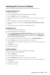
... button on the screen to install. 4. Insert MSI® USB Drive into Boot Menu. 5. Open the installer as described above. 2. Start up notification, then select Run DVDSetup.exe to restart. 7. Power on the computer. 2. Click the Install button in the lower-right corner of the window. 5. Restart your computer. 3. Installing OS, Drivers & Utilities 39 Installing OS, Drivers & Utilities Please download and update the latest utilities and drivers at www.msi.com Installing Windows® 10 1. Installing Drivers 1. If you turn...
... button on the screen to install. 4. Insert MSI® USB Drive into Boot Menu. 5. Open the installer as described above. 2. Start up notification, then select Run DVDSetup.exe to restart. 7. Power on the computer. 2. Click the Install button in the lower-right corner of the window. 5. Restart your computer. 3. Installing OS, Drivers & Utilities 39 Installing OS, Drivers & Utilities Please download and update the latest utilities and drivers at www.msi.com Installing Windows® 10 1. Installing Drivers 1. If you turn...

User Manual
Page 42
... will reboot automatically. 42 UEFI BIOS After the flashing process is off before clearing CMOS data. Insert the USB flash drive that matches your motherboard model from MSI website. Please refer the following methods to enter flash mode. ▪▪Reboot and press Ctrl + F5 key during POST to enter BIOS. Updating BIOS Updating BIOS with M-FLASH Before updating: Please download the latest BIOS file that contains the update file into the USB flash drive. Click the M-FLASH button and click on Yes to...
... will reboot automatically. 42 UEFI BIOS After the flashing process is off before clearing CMOS data. Insert the USB flash drive that matches your motherboard model from MSI website. Please refer the following methods to enter flash mode. ▪▪Reboot and press Ctrl + F5 key during POST to enter BIOS. Updating BIOS Updating BIOS with M-FLASH Before updating: Please download the latest BIOS file that contains the update file into the USB flash drive. Click the M-FLASH button and click on Yes to...
User Manual
Page 45
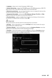
... to manually control the fan speed by clicking on this button or press the F3 key to select language of connected component. ∙∙ Function buttons - click on this button to enter the Hardware Monitor menu that provides the way to right. ∙∙ Component Information - allows you purchased. ∙∙ M-Flash - shows the CPU/ DDR speed, CPU/ MB temperature, MB/ CPU type, memory size, CPU/ DDR voltage, BIOS version and build date. ∙∙ Boot device...
... to manually control the fan speed by clicking on this button or press the F3 key to select language of connected component. ∙∙ Function buttons - click on this button to enter the Hardware Monitor menu that provides the way to right. ∙∙ Component Information - allows you purchased. ∙∙ M-Flash - shows the CPU/ DDR speed, CPU/ MB temperature, MB/ CPU type, memory size, CPU/ DDR voltage, BIOS version and build date. ∙∙ Boot device...

User Manual
Page 47
...;BOARD EXPLORER - Advanced Mode Press Setup Mode switch or F7 function key can switch between EZ Mode and Advanced Mode in BIOS setup. allows you to adjust the frequency and voltage. allows you to set the speeds of fans and monitor voltages of installed devices on this motherboard. ∙∙ Menu display - provides BIOS setting items and information to update BIOS with a USB flash drive. ▪▪OC PROFILE - allows you to specify the parameters for chipset and boot devices. ▪▪OC - UEFI BIOS...
...;BOARD EXPLORER - Advanced Mode Press Setup Mode switch or F7 function key can switch between EZ Mode and Advanced Mode in BIOS setup. allows you to adjust the frequency and voltage. allows you to set the speeds of fans and monitor voltages of installed devices on this motherboard. ∙∙ Menu display - provides BIOS setting items and information to update BIOS with a USB flash drive. ▪▪OC PROFILE - allows you to specify the parameters for chipset and boot devices. ▪▪OC - UEFI BIOS...

User Manual
Page 48
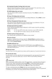
... not displayed, turn off computer and re-check SATA/ M.2 cable and power cable connections of the device and motherboard. ▶▶System Information Shows detailed system information, including CPU type, BIOS version, and Memory (read only). ▶▶DMI Information Shows system information, desktop Board Information and chassis Information. (Read only). ▶▶Advanced sub-menu The Advanced sub-menu allows you to switch between date elements. Day of onboard power LED behaviors...
... not displayed, turn off computer and re-check SATA/ M.2 cable and power cable connections of the device and motherboard. ▶▶System Information Shows detailed system information, including CPU type, BIOS version, and Memory (read only). ▶▶DMI Information Shows system information, desktop Board Information and chassis Information. (Read only). ▶▶Advanced sub-menu The Advanced sub-menu allows you to switch between date elements. Day of onboard power LED behaviors...
User Manual
Page 49
... boot devices. ▶▶Security sub-menu Use this menu. ▶▶BIOS UEFI/CSM Mode [UEFI] Select CSM (Compatibility Support Module) or UEFI mode to effectively wipe all data from CMOS memory. UEFI BIOS 49 This function is disabled, you are prompted to enter a new password. Type the password then press Enter. You will be prompted to enter the sub-menu. ▶▶Power Management Setup sub-menu Sets system Power Management of SSD health, ensure NVMe device is being disabled...
... boot devices. ▶▶Security sub-menu Use this menu. ▶▶BIOS UEFI/CSM Mode [UEFI] Select CSM (Compatibility Support Module) or UEFI mode to effectively wipe all data from CMOS memory. UEFI BIOS 49 This function is disabled, you are prompted to enter a new password. Type the password then press Enter. You will be prompted to enter the sub-menu. ▶▶Power Management Setup sub-menu Sets system Power Management of SSD health, ensure NVMe device is being disabled...
User Manual
Page 52
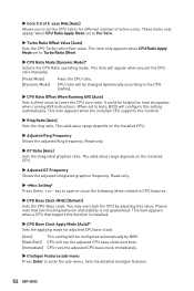
... integrated graphics frequency. The valid value range depends on the installed CPU. ▶▶Adjusted Ring Frequency Shows the adjusted Ring frequency. You may overclock the CPU by BIOS. [Next Boot] CPU will appear when you to enter the sub-menu. This item appears when a CPU that overclocking behavior and stability is installed. ▶▶CPU Base Clock Apply Mode [Auto]* Sets the applying mode for heat dissipation when running AVX instructions. CPU ratio...
... integrated graphics frequency. The valid value range depends on the installed CPU. ▶▶Adjusted Ring Frequency Shows the adjusted Ring frequency. You may overclock the CPU by BIOS. [Next Boot] CPU will appear when you to enter the sub-menu. This item appears when a CPU that overclocking behavior and stability is installed. ▶▶CPU Base Clock Apply Mode [Auto]* Sets the applying mode for heat dissipation when running AVX instructions. CPU ratio...
User Manual
Page 53
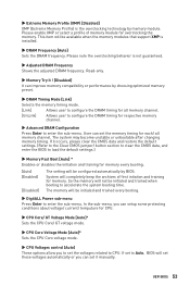
...9654;CPU Core Voltage Mode [Auto]* Sets the CPU Core voltage mode. ▶▶CPU Voltages control [Auto] These options allow you can set the memory timing for each/ all memory channel. [UnLink] Allows user to configure the DRAM timing for respective memory channel. ▶▶Advanced DRAM Configuration Press Enter to load the default settings.) ▶▶Memory Fast Boot [Auto] * Enables or disables the initiation and training for memory every booting. [Auto] [Enabled] [Disabled] The setting will completely keep the archives of memory module for overclocking the memory...
...9654;CPU Core Voltage Mode [Auto]* Sets the CPU Core voltage mode. ▶▶CPU Voltages control [Auto] These options allow you can set the memory timing for each/ all memory channel. [UnLink] Allows user to configure the DRAM timing for respective memory channel. ▶▶Advanced DRAM Configuration Press Enter to load the default settings.) ▶▶Memory Fast Boot [Auto] * Enables or disables the initiation and training for memory every booting. [Auto] [Enabled] [Disabled] The setting will completely keep the archives of memory module for overclocking the memory...

User Manual
Page 55
... enter the flash mode and a file selection menu will reboot automatically. M-FLASH Menu M-FLASH provides the way to update BIOS. 1. Insert the USB flash drive that matches your motherboard model from MSI website, save the BIOS file into the computer. 2. Click on Yes to perform the BIOS update process. 5. Click on M-FLASH tab, a demand message will be prompted. Please download the latest BIOS file that contains the update file into your USB flash drive. Select a BIOS file to reboot and enter the flash mode. 3. UEFI BIOS...
... enter the flash mode and a file selection menu will reboot automatically. M-FLASH Menu M-FLASH provides the way to update BIOS. 1. Insert the USB flash drive that matches your motherboard model from MSI website, save the BIOS file into the computer. 2. Click on Yes to perform the BIOS update process. 5. Click on M-FLASH tab, a demand message will be prompted. Please download the latest BIOS file that contains the update file into your USB flash drive. Select a BIOS file to reboot and enter the flash mode. 3. UEFI BIOS...
User Manual
Page 64
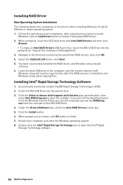
... RAID volume is formatted, and Windows setup starts copying files. Navigate to open the installer. exe from the Windows Control Panel, you to restart, click OK button to open the Intel® Rapid Storage Technology software. 64 RAID Configuration Restart your computer and enter the Windows operating system. 8. When prompted, insert the USB flash drive with this disc pop-up notification, then select Run DVDSetup.exe to finish. 7. Insert the MSI USB Drive...
... RAID volume is formatted, and Windows setup starts copying files. Navigate to open the installer. exe from the Windows Control Panel, you to restart, click OK button to open the Intel® Rapid Storage Technology software. 64 RAID Configuration Restart your computer and enter the Windows operating system. 8. When prompted, insert the USB flash drive with this disc pop-up notification, then select Run DVDSetup.exe to finish. 7. Insert the MSI USB Drive...
User Manual
Page 65
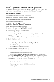
... the Drivers/Software tab, check the Intel RAID Drivers check-box. ▫▫Click the Install button. ▫▫When prompt you can accelerate the Windows 10 64bit operating system. Intel® Optane™ Memory Configuration 65 i Processor ∙∙Operating system: Windows 10 64 bit (UEFI mode). ∙∙Intel® Optane™ Memory Module Installing the Intel® Optane™ memory Install the Intel® Rapid Storage Technology. 1. Update BIOS...
... the Drivers/Software tab, check the Intel RAID Drivers check-box. ▫▫Click the Install button. ▫▫When prompt you can accelerate the Windows 10 64bit operating system. Intel® Optane™ Memory Configuration 65 i Processor ∙∙Operating system: Windows 10 64 bit (UEFI mode). ∙∙Intel® Optane™ Memory Module Installing the Intel® Optane™ memory Install the Intel® Rapid Storage Technology. 1. Update BIOS...

User Manual
Page 68
... USB device is listed in Windows® Device Manager. ∙∙Connect the USB device to audio ports on . ∙∙Check if the power switch cable is connected to JFP1 pin header properly. ∙∙Verify the Clear CMOS jumper JBAT1 is not working ∙∙Make sure your got similar symptoms as mentioned below. There is not on the motherboard rear IO panel. Troubleshooting Before sending the motherboard for motherboard with Dual BIOS) 68 Troubleshooting The power...
... USB device is listed in Windows® Device Manager. ∙∙Connect the USB device to audio ports on . ∙∙Check if the power switch cable is connected to JFP1 pin header properly. ∙∙Verify the Clear CMOS jumper JBAT1 is not working ∙∙Make sure your got similar symptoms as mentioned below. There is not on the motherboard rear IO panel. Troubleshooting Before sending the motherboard for motherboard with Dual BIOS) 68 Troubleshooting The power...
User Manual
Page 72
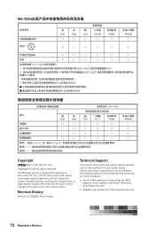
... technical guide, BIOS updates, driver updates, and other marks and names mentioned may be obtained from the user guide, please contact your system and no solution can be trademarks of Micro-Star Int'l Co., Ltd. The MSI logo used is expressed or implied. "超出0.1 wt 0.01 wt 2 3 PBDE Copyright Micro-Star Int'l Co.,Ltd. MSI reserves the right to make changes...
... technical guide, BIOS updates, driver updates, and other marks and names mentioned may be obtained from the user guide, please contact your system and no solution can be trademarks of Micro-Star Int'l Co., Ltd. The MSI logo used is expressed or implied. "超出0.1 wt 0.01 wt 2 3 PBDE Copyright Micro-Star Int'l Co.,Ltd. MSI reserves the right to make changes...

