User Guide
Page 2
...-language version for PCB 1.x April 2004 with chipsets VIA® KM400/KM400A/KM266 Pro & VT8237 V1.1 FSB Clock jumpers (SW1&SW2) & SATA1/2 update May 2004 V1.2 Update FSB frequency contents July 2004 ii Windows® 98/2000/NT/XP are registered trademarks of Microsoft Corporation. AMD, Athlon...Corporation. AMI® is the intellectual property of MICRO-STAR INTERNATIONAL. Award® is given as to make changes without notice. Revision History Revision Revision History Date V1.0 First released of Phoenix Technologies Ltd. We take every care in the United States...
...-language version for PCB 1.x April 2004 with chipsets VIA® KM400/KM400A/KM266 Pro & VT8237 V1.1 FSB Clock jumpers (SW1&SW2) & SATA1/2 update May 2004 V1.2 Update FSB frequency contents July 2004 ii Windows® 98/2000/NT/XP are registered trademarks of Microsoft Corporation. AMD, Athlon...Corporation. AMI® is the intellectual property of MICRO-STAR INTERNATIONAL. Award® is given as to make changes without notice. Revision History Revision Revision History Date V1.0 First released of Phoenix Technologies Ltd. We take every care in the United States...
User Guide
Page 3
...card or module. 9. The power cord or plug is incorrectly replaced. The equipment does not work according to User Manual. - The equipment has obvious sign of the following situations arises, get it . CAUTION: Danger of the power source and adjust properly 110/220V before inserting any of breakage. 12. Make sure the voltage of explosion if battery...be noted. 10. Keep this equipment on it work well or you can not step on a reliable flat surface before setting it may damage the equipment. Do not leave this User Manual for air convection hence protects the equipment from ...
...card or module. 9. The power cord or plug is incorrectly replaced. The equipment does not work according to User Manual. - The equipment has obvious sign of the following situations arises, get it . CAUTION: Danger of the power source and adjust properly 110/220V before inserting any of breakage. 12. Make sure the voltage of explosion if battery...be noted. 10. Keep this equipment on it work well or you can not step on a reliable flat surface before setting it may damage the equipment. Do not leave this User Manual for air convection hence protects the equipment from ...
User Guide
Page 5
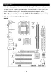
Layout Top : mouse Bottom: keyboard SOCKET 462 FANCPU1 CONN 1 FDD 1 Top : Parallel Port Bottom: COM A VGA port FANSYS1 ATX Power Supply DIMM 2 DIMM 1 USB ports JPW1 Top: LAN Jack Bottom: USB ports VIA VT6103 Line-In Line-Out Mic COM2 Winbond W83697HF AGP Slot PCI Slot 1 BIOS JCD1 VIA VT1617A PCI Slot 2 PCI Slot 3 JAUD1 VIA VT8237 SATA2 (for KM400/ KM400A) SATA1 (for choosing the KM4M-V/KM4AM-V/KM3M-V Series (MS-7061 v1.X) micro ATX mainboard. Introduction Thank you...
Layout Top : mouse Bottom: keyboard SOCKET 462 FANCPU1 CONN 1 FDD 1 Top : Parallel Port Bottom: COM A VGA port FANSYS1 ATX Power Supply DIMM 2 DIMM 1 USB ports JPW1 Top: LAN Jack Bottom: USB ports VIA VT6103 Line-In Line-Out Mic COM2 Winbond W83697HF AGP Slot PCI Slot 1 BIOS JCD1 VIA VT1617A PCI Slot 2 PCI Slot 3 JAUD1 VIA VT8237 SATA2 (for KM400/ KM400A) SATA1 (for choosing the KM4M-V/KM4AM-V/KM3M-V Series (MS-7061 v1.X) micro ATX mainboard. Introduction Thank you...
User Guide
Page 6
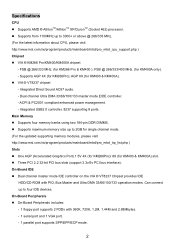
... power management. - Supports from 1100MHz up to 2GB for KM400 & KM400A) slot. ! AGP 8X (for KM400A only). - Supports four memory banks using two 184-pin DDR DIMMS. ! Three PCI 2.2 32-bit PCI bus slots (support 3.3v/5v PCI bus interface). On-Board Peripherals ! Supports AMD ® AthlonTM/AthlonTM XP/DuronTM (Socket 462) processor. ! Main Memory ! Dual channel master mode IDE controller on the VIA ® VT8237 Chipset provides IDE HDD/CD-ROM with 360K, 720K, 1.2M, 1.44M and 2.88Mbytes. - 1 serial port and 1 VGA port. - 1 parallel port supports...
... power management. - Supports from 1100MHz up to 2GB for KM400 & KM400A) slot. ! AGP 8X (for KM400A only). - Supports four memory banks using two 184-pin DDR DIMMS. ! Three PCI 2.2 32-bit PCI bus slots (support 3.3v/5v PCI bus interface). On-Board Peripherals ! Supports AMD ® AthlonTM/AthlonTM XP/DuronTM (Socket 462) processor. ! Main Memory ! Dual channel master mode IDE controller on the VIA ® VT8237 Chipset provides IDE HDD/CD-ROM with 360K, 720K, 1.2M, 1.44M and 2.88Mbytes. - 1 serial port and 1 VGA port. - 1 parallel port supports...
User Guide
Page 7
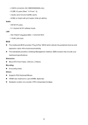
... devices and expansion cards of the board automatically. ! Micro-ATX Form Factor: 245 mm x 192mm. Audio - The mainboard provides a Desktop Management Interface (DMI) function that records your mainboard specifications. VRAM size maximum is to 64MB. (Optional). ! Others ! VIA VT8237 integrated MAC + VIA 6103 PHY. - 1 RJ45 LAN Jack. BIOS ! Dimension ! Hardware monitor is up to monitor CPU's temperature/voltage. 3 Supports PS2 Keyboard/Mouse. ! COM2 on board with pin header (Intel pin-define). - 2 SATA connectors (for KM400/KM400A only) - 8 USB 2.0 ports...
... devices and expansion cards of the board automatically. ! Micro-ATX Form Factor: 245 mm x 192mm. Audio - The mainboard provides a Desktop Management Interface (DMI) function that records your mainboard specifications. VRAM size maximum is to 64MB. (Optional). ! Others ! VIA VT8237 integrated MAC + VIA 6103 PHY. - 1 RJ45 LAN Jack. BIOS ! Dimension ! Hardware monitor is up to monitor CPU's temperature/voltage. 3 Supports PS2 Keyboard/Mouse. ! COM2 on board with pin header (Intel pin-define). - 2 SATA connectors (for KM400/KM400A only) - 8 USB 2.0 ports...
User Guide
Page 8
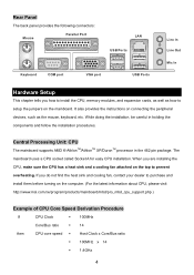
... then CPU core speed = Host Clock x Core/Bus ratio = 100MHz x 14 = 1.4GHz 4 It also provides the instructions on connecting the peripheral devices, such as how to setup the jumpers on the top to prevent overheating. Rear Panel The back panel provides the following connectors: Mouse Parallel Port LAN USB Ports Keyboard COM port VGA port USB Ports Line In Line Out Mic In Hardware Setup This chapter tells you how to install the CPU, memory modules, and expansion cards...
... then CPU core speed = Host Clock x Core/Bus ratio = 100MHz x 14 = 1.4GHz 4 It also provides the instructions on connecting the peripheral devices, such as how to setup the jumpers on the top to prevent overheating. Rear Panel The back panel provides the following connectors: Mouse Parallel Port LAN USB Ports Keyboard COM port VGA port USB Ports Line In Line Out Mic In Hardware Setup This chapter tells you how to install the CPU, memory modules, and expansion cards...
User Guide
Page 9
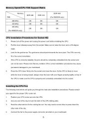
...Use one end of the clip to the power supply connector provided on top of the correct installation procedures may need a screw drive to press down firmly into the socket and close the lever with your agent for the proper CPU cooler set onto the CPU. 2. Memory Speed/CPU FSB Support Matrix Memory...of the CPU sliding plate. 3. Look for Socket 462 1. Make sure to raise the lever up to your CPU cooler set . 1. Please turn off the power and unplug the power cord before installing the CPU. 2. Position your mainboard. 5. Installing the CPU Fan The following instructions will guide you ...
...Use one end of the clip to the power supply connector provided on top of the correct installation procedures may need a screw drive to press down firmly into the socket and close the lever with your agent for the proper CPU cooler set onto the CPU. 2. Memory Speed/CPU FSB Support Matrix Memory...of the CPU sliding plate. 3. Look for Socket 462 1. Make sure to raise the lever up to your CPU cooler set . 1. Please turn off the power and unplug the power cord before installing the CPU. 2. Position your mainboard. 5. Installing the CPU Fan The following instructions will guide you ...
User Guide
Page 10
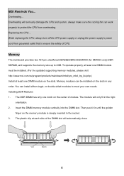
... side of module. Memory The mainboard provides two 184-pin unbuffered DDR266/DDR333/DDR400 (for KM400A only) DDR SDRAM, and supports the memory size up to meet your own needs. Overheating will seriously damage the CPU and system, always make sure the cooling fan can install either single- While replacing the CPU, always turn off the ATX power supply or unplug the power supply's power cord from overheating...
... side of module. Memory The mainboard provides two 184-pin unbuffered DDR266/DDR333/DDR400 (for KM400A only) DDR SDRAM, and supports the memory size up to meet your own needs. Overheating will seriously damage the CPU and system, always make sure the cooling fan can install either single- While replacing the CPU, always turn off the ATX power supply or unplug the power supply's power cord from overheating...
User Guide
Page 11
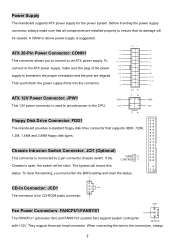
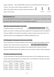
... must enter the BIOS setting and clear the status. To PS_ON GND connect to the ATX power supply, make sure that supports 360K, 720K, 1.2M, 1.44M and 2.88M floppy disk types. To clear the warning, you to connect to an ATX power supply. L GND Fan Power Connectors: FANCPU1/FANSYS1 +12V The FANCPU1 (processor fan) and FANSYS1 (system fan) support system cooling fan SENSOR with +12V. A 300W or above power supply is used to provide power to the connectors, always 7 Power Supply The mainboard supports ATX power supply...
... must enter the BIOS setting and clear the status. To PS_ON GND connect to the ATX power supply, make sure that supports 360K, 720K, 1.2M, 1.44M and 2.88M floppy disk types. To clear the warning, you to connect to an ATX power supply. L GND Fan Power Connectors: FANCPU1/FANSYS1 +12V The FANCPU1 (processor fan) and FANSYS1 (system fan) support system cooling fan SENSOR with +12V. A 300W or above power supply is used to provide power to the connectors, always 7 Power Supply The mainboard supports ATX power supply...
User Guide
Page 12
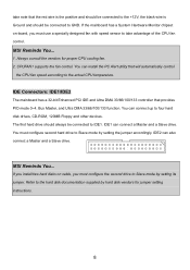
... Alert utility that will automatically control the CPU fan speed according to four hard disk drives, CD-ROM, 120MB Floppy and other devices. You must configure second hard drive to Slave mode by hard disk vendors for proper CPU cooling fan. 2. Always consult the vendors for jumper setting instructions. 8 IDE Connectors: IDE1/IDE2 The mainboard has a 32-bit Enhanced PCI IDE and Ultra DMA 33/66/100/133 controller that the red wire is the positive and should be connected to...
... Alert utility that will automatically control the CPU fan speed according to four hard disk drives, CD-ROM, 120MB Floppy and other devices. You must configure second hard drive to Slave mode by hard disk vendors for proper CPU cooling fan. 2. Always consult the vendors for jumper setting instructions. 8 IDE Connectors: IDE1/IDE2 The mainboard has a 32-bit Enhanced PCI IDE and Ultra DMA 33/66/100/133 controller that the red wire is the positive and should be connected to...

User Guide
Page 13
... 40 times faster than USB 1.1, and is ideal for electrical connection to the front panel audio and is compliant with Intel Front Panel I /O Connectivity Design Guide. It is compliant with Intel ® Front Panel I /O Connectivity Design Guide. Power Power LED Switch 2 10 1 9 HDD Reset LED Switch JFP1 Speaker 2 8 1 7 Power LED JFP2 Front Panel Audio Connector: JAUD1 The front panel audio connector allows you do not want to connect to the front audio header, pins 5 & 6, 9 & 10 have to be jumpered in order to...
... 40 times faster than USB 1.1, and is ideal for electrical connection to the front panel audio and is compliant with Intel Front Panel I /O Connectivity Design Guide. It is compliant with Intel ® Front Panel I /O Connectivity Design Guide. Power Power LED Switch 2 10 1 9 HDD Reset LED Switch JFP1 Speaker 2 8 1 7 Power LED JFP2 Front Panel Audio Connector: JAUD1 The front panel audio connector allows you do not want to connect to the front audio header, pins 5 & 6, 9 & 10 have to be jumpered in order to...
User Guide
Page 14
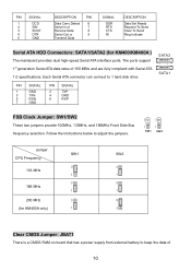
... PIN SIGNAL 1 DCD 2 SIN 3 SOUT 4 DTR 5 GND DESCRIPTION PIN Data Carry Detect 6 Serial In or 7 Receive Data 8 Serial Out or 9 Transmit Data SIGNAL DSR RTS CTS RI DESCRIPTION Data Set Ready Request To Send Clear To Send Ring Indicate Serial ATA HDD Connectors: SATA1/SATA2 (for KM400A only) SW1 3 1 3 1 3 1 SW2 3 1 3 1 3 1 Clear CMOS Jumper: JBAT1 There is a CMOS RAM on board that has a power supply from external battery to 1 hard disk drive...
... PIN SIGNAL 1 DCD 2 SIN 3 SOUT 4 DTR 5 GND DESCRIPTION PIN Data Carry Detect 6 Serial In or 7 Receive Data 8 Serial Out or 9 Transmit Data SIGNAL DSR RTS CTS RI DESCRIPTION Data Set Ready Request To Send Clear To Send Ring Indicate Serial ATA HDD Connectors: SATA1/SATA2 (for KM400A only) SW1 3 1 3 1 3 1 SW2 3 1 3 1 3 1 Clear CMOS Jumper: JBAT1 There is a CMOS RAM on board that has a power supply from external battery to 1 hard disk drive...
User Guide
Page 15
... or software settings for the expansion card to make sure that you want to clear the system configuration, use the 3 3 JBAT1 (Clear CMOS Jumper) to insert the AGP graphics card. It introduces a 66MHz, 32-bit channel for KM400 & KM400A) AGP card. The mainboard supports 4X (for KM266Pro)/8X (for the graphics controller to the PCI bus INT A# ~ INT D# pins as jumpers, switches or BIOS configuration. Meanwhile, read the documentation for the expansion card, such as follows: PCI Slot 1 PCI Slot 2 PCI Slot...
... or software settings for the expansion card to make sure that you want to clear the system configuration, use the 3 3 JBAT1 (Clear CMOS Jumper) to insert the AGP graphics card. It introduces a 66MHz, 32-bit channel for KM400 & KM400A) AGP card. The mainboard supports 4X (for KM266Pro)/8X (for the graphics controller to the PCI bus INT A# ~ INT D# pins as jumpers, switches or BIOS configuration. Meanwhile, read the documentation for the expansion card, such as follows: PCI Slot 1 PCI Slot 2 PCI Slot...
User Guide
Page 16
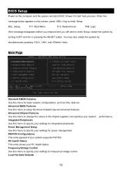
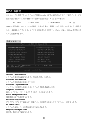
... the RESET button. Advanced BIOS Features Use this menu for integrated peripherals. Load Fail-Safe Defaults 12 Main Page Standard CMOS Features Use this menu to setup the items of Award special enhanced features. PC Health Status This entry shows your system supports PnP/PCI. Advanced Chipset Features Use this menu to specify your settings for frequency/voltage control. Integrated Peripherals Use this menu to change the values in the chipset registers and optimize your settings for power management. BIOS Setup Power...
... the RESET button. Advanced BIOS Features Use this menu for integrated peripherals. Load Fail-Safe Defaults 12 Main Page Standard CMOS Features Use this menu to setup the items of Award special enhanced features. PC Health Status This entry shows your system supports PnP/PCI. Advanced Chipset Features Use this menu to specify your settings for frequency/voltage control. Integrated Peripherals Use this menu to change the values in the chipset registers and optimize your settings for power management. BIOS Setup Power...
User Guide
Page 18
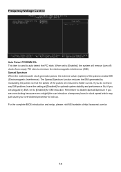
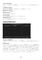
... (spikes) of the pulses are overclocking because even a slight jitter can introduce a temporary boost in clock speed which may just cause your overclocked processor to minimize the electromagnetic interference (EMI). But if you do not have any EMI problem, leave the setting at http://www.msi.com.tw. 14 Frequency/Voltage Control Auto Detect PCI/DIMM Clk This item is used to auto detect the PCI slots.
... (spikes) of the pulses are overclocking because even a slight jitter can introduce a temporary boost in clock speed which may just cause your overclocked processor to minimize the electromagnetic interference (EMI). But if you do not have any EMI problem, leave the setting at http://www.msi.com.tw. 14 Frequency/Voltage Control Auto Detect PCI/DIMM Clk This item is used to auto detect the PCI slots.
User Guide
Page 60
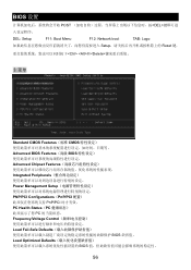
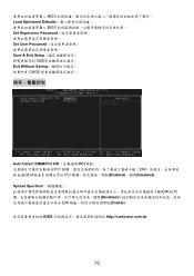
BIOS 设置 POST DEL DEL: Setup F11: Boot Menu F12: Network boot TAB: Logo Setup Reset 键, Ctrl> 和
BIOS 设置 POST DEL DEL: Setup F11: Boot Menu F12: Network boot TAB: Logo Setup Reset 键, Ctrl> 和
User Guide
Page 74
BIOS Load Optimized Defaults BIOS Set Supervisor Password Set User Password Save & Exit Setup CMOS Exit Without Saving CMOS Auto Detect DIMM/PCI ClK PCI PCI EMI PCI Enabled)、關閉(Disabled)。 Spread Spectrum EMI Disabled EMI Enable BIOS http://cweb.msi.com.tw 70
BIOS Load Optimized Defaults BIOS Set Supervisor Password Set User Password Save & Exit Setup CMOS Exit Without Saving CMOS Auto Detect DIMM/PCI ClK PCI PCI EMI PCI Enabled)、關閉(Disabled)。 Spread Spectrum EMI Disabled EMI Enable BIOS http://cweb.msi.com.tw 70
User Guide
Page 91
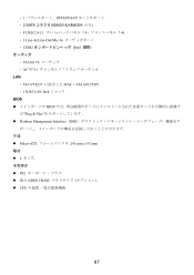
- 1 SPP/EPP/ECP 2 SATA KM400 & KM400A のみ) - 8 USB 2.0/1.1 4 4) - 3 Line-In/Line-Out/Mic-In COM2 Intel VIA1617A AC'97 5.1 LAN - VIA VT8237 MAC + VIA 6103 PHY - 1 RJ45 LAN Jack BIOS BIOS Plug & Play Desktop Management Interface(DMI Micro-ATX 245 mm x 192mm 取付 ! 6 PS2 64MB VRAM CPU 87
- 1 SPP/EPP/ECP 2 SATA KM400 & KM400A のみ) - 8 USB 2.0/1.1 4 4) - 3 Line-In/Line-Out/Mic-In COM2 Intel VIA1617A AC'97 5.1 LAN - VIA VT8237 MAC + VIA 6103 PHY - 1 RJ45 LAN Jack BIOS BIOS Plug & Play Desktop Management Interface(DMI Micro-ATX 245 mm x 192mm 取付 ! 6 PS2 64MB VRAM CPU 87
User Guide
Page 101
BIOS の設定 POST(Power On Self Test DEL DEL: Setup F11: Boot Menu F12: Network boot TAB: Logo
BIOS の設定 POST(Power On Self Test DEL DEL: Setup F11: Boot Menu F12: Network boot TAB: Logo
User Guide
Page 102
Load Fail-Safe Defaults BIOS Load Optimized Defaults BIOS Set Supervisor Password Set User Password Save & Exit Setup CMOS Exit Without Saving CMOS Frequency/Voltage Control Auto Detect PCI/DIMM Clk PCI DIMM Spread Spectrum EMI Spread Spectrum EMI EMI Disabled EMI Enabled EMI Disabled 98
Load Fail-Safe Defaults BIOS Load Optimized Defaults BIOS Set Supervisor Password Set User Password Save & Exit Setup CMOS Exit Without Saving CMOS Frequency/Voltage Control Auto Detect PCI/DIMM Clk PCI DIMM Spread Spectrum EMI Spread Spectrum EMI EMI Disabled EMI Enabled EMI Disabled 98


