User Guide
Page 4
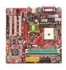
... work according to User's Manual. Technical Support If a problem arises with the same or equivalent type recommended by a service personnel: h The power cord or plug is incorrectly replaced. Alternatively, please try the following situations arises, get it may damage the equipment. com.tw/program/service/faq/faq/esc_faq_list.php h Contact our technical staff at: support@msi.com.tw Safety Instructions 1. Always read the safety instructions...
... work according to User's Manual. Technical Support If a problem arises with the same or equivalent type recommended by a service personnel: h The power cord or plug is incorrectly replaced. Alternatively, please try the following situations arises, get it may damage the equipment. com.tw/program/service/faq/faq/esc_faq_list.php h Contact our technical staff at: support@msi.com.tw Safety Instructions 1. Always read the safety instructions...
User Guide
Page 5
...1-2 Mainboard Layout 1-4 Chapter 2. Hardware Setup 2-1 Quick Components Guide 2-2 Central Processing Unit: CPU 2-3 Memory Speed/CPU FSB Support Matrix 2-3 CPU Installation Procedures for Socket 754 2-4 Installing AMD Athlon64 CPU Cooler Set 2-5 Memory ...2-7 Introduction to DDR SDRAM 2-7 DDR DIMM Module Combination 2-8 Installing DDR Modules 2-8 Power Supply ...2-9 ATX 20-Pin Power Connector: JWR1 2-9 ATX 12V Power Connector: JPW1 2-9 Back Panel ...2-10 View of the Back Panel 2-10 Serial Port: COMA 2-11 Mouse Connector 2-11 Keyboard Connector 2-11 VGA Connector 2-11 USB Ports...
...1-2 Mainboard Layout 1-4 Chapter 2. Hardware Setup 2-1 Quick Components Guide 2-2 Central Processing Unit: CPU 2-3 Memory Speed/CPU FSB Support Matrix 2-3 CPU Installation Procedures for Socket 754 2-4 Installing AMD Athlon64 CPU Cooler Set 2-5 Memory ...2-7 Introduction to DDR SDRAM 2-7 DDR DIMM Module Combination 2-8 Installing DDR Modules 2-8 Power Supply ...2-9 ATX 20-Pin Power Connector: JWR1 2-9 ATX 12V Power Connector: JPW1 2-9 Back Panel ...2-10 View of the Back Panel 2-10 Serial Port: COMA 2-11 Mouse Connector 2-11 Keyboard Connector 2-11 VGA Connector 2-11 USB Ports...
User Guide
Page 6
... Status 3-20 Frequency/Voltage Control 3-21 Set Supervisor/User Password 3-23 Load High Performance/BIOS Setup Defaults 3-24 Appendix A: Using 4- Serial ATA/Serial ATA RAID Connectors controlled by VT8237: SATA1 & SATA2 2-16 Front Panel Connectors: JFP1 & JFP2 2-17 CD-In Connector: JCD1 2-17 Front Panel Audio Connector: JAUD1 2-18 IrDA Infrared Module Header: JIR1 (Optional 2-18 IEEE 1394 Connector: J1394_1 2-18 SPDIF-Out Connector: JSP1 (Optional 2-18 Jumpers ...2-20 Clear CMOS Jumper: JBAT1 2-20 Slots ...2-21 AGP (Accelerated Graphics Port) Slot 2-21 PCI (Peripheral Component...
... Status 3-20 Frequency/Voltage Control 3-21 Set Supervisor/User Password 3-23 Load High Performance/BIOS Setup Defaults 3-24 Appendix A: Using 4- Serial ATA/Serial ATA RAID Connectors controlled by VT8237: SATA1 & SATA2 2-16 Front Panel Connectors: JFP1 & JFP2 2-17 CD-In Connector: JCD1 2-17 Front Panel Audio Connector: JAUD1 2-18 IrDA Infrared Module Header: JIR1 (Optional 2-18 IEEE 1394 Connector: J1394_1 2-18 SPDIF-Out Connector: JSP1 (Optional 2-18 Jumpers ...2-20 Clear CMOS Jumper: JBAT1 2-20 Slots ...2-21 AGP (Accelerated Graphics Port) Slot 2-21 PCI (Peripheral Component...

User Guide
Page 9
... - 1 serial port (COM A) - 1 parallel port supports SPP/EPP/ECP mode - 1 IrDA connector for two 184pin DDR DIMMs. Supports DIMM sizes up to two Serial ATA drives. Chipset VIA K8T 800/K8M800 Chipset (578-pin BGA) -HyperTransportTM connection to 150MB/sec transfer speeds. - Supports 2 Serial ATA ports - Three 32-bit/33 MHz PCI slots. Slots One AGP 8x/4x slot. MS-6741 Micro-ATX Mainboard Mainboard Specifications CPU Supports 64-bit AMD® K8 Athlon 64 processor (Socket 754). Up to AMD K8 Athlon64 processor -8 or 16 bit control...
... - 1 serial port (COM A) - 1 parallel port supports SPP/EPP/ECP mode - 1 IrDA connector for two 184pin DDR DIMMs. Supports DIMM sizes up to two Serial ATA drives. Chipset VIA K8T 800/K8M800 Chipset (578-pin BGA) -HyperTransportTM connection to 150MB/sec transfer speeds. - Supports 2 Serial ATA ports - Three 32-bit/33 MHz PCI slots. Slots One AGP 8x/4x slot. MS-6741 Micro-ATX Mainboard Mainboard Specifications CPU Supports 64-bit AMD® K8 Athlon 64 processor (Socket 754). Up to AMD K8 Athlon64 processor -8 or 16 bit control...

User Guide
Page 25
... GND Fan Connector Pin Definition MSI Reminds You... When connecting the wire to the connectors, always take advantage of the system case, audio ports, USB Ports, and CPU/System FANs. FDD1 Fan Power Connectors: CFAN1, SFAN1 The CAN1 (processor fan) and SFAN1 (system fan) support system cooling fan with speed sensor to take note that supports 360KB, 720KB, 1.2MB, 1.44MB and 2.88MB floppy disk types. If the mainboard has a System Hardware Monitor chipset on-board, you must use a specially designed fan with +12V. Floppy Disk Drive Connector...
... GND Fan Connector Pin Definition MSI Reminds You... When connecting the wire to the connectors, always take advantage of the system case, audio ports, USB Ports, and CPU/System FANs. FDD1 Fan Power Connectors: CFAN1, SFAN1 The CAN1 (processor fan) and SFAN1 (system fan) support system cooling fan with speed sensor to take note that supports 360KB, 720KB, 1.2MB, 1.44MB and 2.88MB floppy disk types. If the mainboard has a System Hardware Monitor chipset on-board, you must use a specially designed fan with +12V. Floppy Disk Drive Connector...

User Guide
Page 26
... USB ports. 9 1 10 2 JUSB1/JUSB2 Pin Definition Pin Description 1 USBPWR 3 USBP25 USBP2+ 7 GND 9 NC Pin Description 2 USBPWR 4 USBP36 USBP3+ 8 GND 10 OC # 2-15 Front USB Connectors: JUSB1 & JUSB2 The mainboard provide two front Universal Serial Bus connectors for users to connect to four hard disk drives, CD-ROM drives, 120MB floppy disk drive (reserved for jumper setting instructions. Hardware Setup Hard Disk Connectors: IDE1 & IDE2 The mainboard provides a 32-bit Enhanced PCI IDE and Ultra DMA 33/66/100/133 controller that supports PIO mode 0 ~ 4, Bus...
... USB ports. 9 1 10 2 JUSB1/JUSB2 Pin Definition Pin Description 1 USBPWR 3 USBP25 USBP2+ 7 GND 9 NC Pin Description 2 USBPWR 4 USBP36 USBP3+ 8 GND 10 OC # 2-15 Front USB Connectors: JUSB1 & JUSB2 The mainboard provide two front Universal Serial Bus connectors for users to connect to four hard disk drives, CD-ROM drives, 120MB floppy disk drive (reserved for jumper setting instructions. Hardware Setup Hard Disk Connectors: IDE1 & IDE2 The mainboard provides a 32-bit Enhanced PCI IDE and Ultra DMA 33/66/100/133 controller that supports PIO mode 0 ~ 4, Bus...

User Guide
Page 29
... audio header, pins 5 & 6, 9 & 10 have to be jumpered in order to have signal output directed to front panel 6 AUD_RET_R Right channel audio signal return from front panel MSI Reminds You... JIR1 is compliant with Intel® Front Panel I/O Connectivity Design Guide. 6 5 JIR1 2 1 JIR1 Pin Definition Pin Signal 1 NC 2 NC 3 VCC5 4 GND 5 IRTX 6 IRRX 2-18 MS-6741 Micro-ATX Mainboard Front Panel Audio Connector: JAUD1 The mainboard provides one front audio connector for future use...
... audio header, pins 5 & 6, 9 & 10 have to be jumpered in order to have signal output directed to front panel 6 AUD_RET_R Right channel audio signal return from front panel MSI Reminds You... JIR1 is compliant with Intel® Front Panel I/O Connectivity Design Guide. 6 5 JIR1 2 1 JIR1 Pin Definition Pin Signal 1 NC 2 NC 3 VCC5 4 GND 5 IRTX 6 IRRX 2-18 MS-6741 Micro-ATX Mainboard Front Panel Audio Connector: JAUD1 The mainboard provides one front audio connector for future use...
User Guide
Page 31
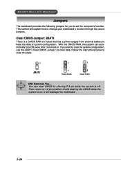
... to keep the data of jumpers. Clear CMOS Jumper: JBAT1 There is on board that has a power supply from external battery to set the computer's function. Then return to clear the data: 1 JBAT1 1 3 Keep Data 1 3 Clear Data MSI Reminds You... Follow the instructions below to 1-2 pin position. Avoid clearing the CMOS while the system is a CMOS RAM on ; MS-6741 Micro-ATX Mainboard Jumpers The mainboard provides the following jumpers for you want to...
... to keep the data of jumpers. Clear CMOS Jumper: JBAT1 There is on board that has a power supply from external battery to set the computer's function. Then return to clear the data: 1 JBAT1 1 3 Keep Data 1 3 Clear Data MSI Reminds You... Follow the instructions below to 1-2 pin position. Avoid clearing the CMOS while the system is a CMOS RAM on ; MS-6741 Micro-ATX Mainboard Jumpers The mainboard provides the following jumpers for you want to...

User Guide
Page 32
... or software settings for the expansion card to the PCI bus INT A# ~ INT D# pins as jumpers, switches or BIOS configuration. It introduces a 66MHz, 32-bit channel for ATX family motherboards. CNR Slot The CNR slot allows you to directly access main memory. The slot supports 8x/4x AGP card. PCI (Peripheral Component Interconnect) Slots The PCI slots allow you unplug the power supply first. CNR is a specially designed audio, or modem riser card for the graphics controller to insert the AGP graphics card. PCI Interrupt...
... or software settings for the expansion card to the PCI bus INT A# ~ INT D# pins as jumpers, switches or BIOS configuration. It introduces a 66MHz, 32-bit channel for ATX family motherboards. CNR Slot The CNR slot allows you to directly access main memory. The slot supports 8x/4x AGP card. PCI (Peripheral Component Interconnect) Slots The PCI slots allow you unplug the power supply first. CNR is a specially designed audio, or modem riser card for the graphics controller to insert the AGP graphics card. PCI Interrupt...

User Guide
Page 34
... to activate the boot menu similar to enter Setup, restart the system by pressing . The system will boot from by simultaneously pressing , , and keys. MS-6741 Micro-ATX Mainboard Entering Setup Power on the system, it OFF and On or pressing the RESET button. Select First Boot Device Floppy IDE-0 CDROM : 1st Floppy : IBM-DTLA-307038 : ATAPI CD-ROM DRIVE 40X M [Up/Dn] Select [RETURN] Boot [ESC] cancel The boot menu will start POST (Power On Self...
... to activate the boot menu similar to enter Setup, restart the system by pressing . The system will boot from by simultaneously pressing , , and keys. MS-6741 Micro-ATX Mainboard Entering Setup Power on the system, it OFF and On or pressing the RESET button. Select First Boot Device Floppy IDE-0 CDROM : 1st Floppy : IBM-DTLA-307038 : ATAPI CD-ROM DRIVE 40X M [Up/Dn] Select [RETURN] Boot [ESC] cancel The boot menu will start POST (Power On Self...

User Guide
Page 41
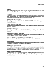
... the main DRAM into cache memory, for the hard disks. Internal Cache Cache memory is additional memory that monitors your disk status to a safe place before the hard disk becomes offline. When enabled, the BIOS will activate the floppy disk drives during the boot process: the drive activity light will come on the Num Lock key when the system is much faster than conventional DRAM (system memory). BIOS Setup Technology) capability for even faster access by the CPU. When...
... the main DRAM into cache memory, for the hard disks. Internal Cache Cache memory is additional memory that monitors your disk status to a safe place before the hard disk becomes offline. When enabled, the BIOS will activate the floppy disk drives during the boot process: the drive activity light will come on the Num Lock key when the system is much faster than conventional DRAM (system memory). BIOS Setup Technology) capability for even faster access by the CPU. When...

User Guide
Page 44
... Fast Write technology allows the CPU to write directly to 15CLK. Select Enabled only when the installed AGP card supports this function. AGP Aperture Size This setting controls just how much system RAM can be incomplete and DRAM may be allocated to 6CLK. Setting options: Auto, 2CLK to AGP for DRAM. The option allows the selection of an aperture size of cycles for the installed AGP card. This setup item...
... Fast Write technology allows the CPU to write directly to 15CLK. Select Enabled only when the installed AGP card supports this function. AGP Aperture Size This setting controls just how much system RAM can be incomplete and DRAM may be allocated to 6CLK. Setting options: Auto, 2CLK to AGP for DRAM. The option allows the selection of an aperture size of cycles for the installed AGP card. This setup item...

User Guide
Page 45
... BIOS supports S3 sleep mode. tem context. BIOS Setup Power Management Features MSI Reminds You... The system resume time is a low power state. If your operating system supports ACPI, such as Windows 98SE, Windows ME and Windows 2000, you disable the function, but system will be used to restore the system when a "wake up (resumes) from S3. 3-13 The information stored in memory will need an AGP driver to enter...
... BIOS supports S3 sleep mode. tem context. BIOS Setup Power Management Features MSI Reminds You... The system resume time is a low power state. If your operating system supports ACPI, such as Windows 98SE, Windows ME and Windows 2000, you disable the function, but system will be used to restore the system when a "wake up (resumes) from S3. 3-13 The information stored in memory will need an AGP driver to enter...

User Guide
Page 48
... default settings. Select Yes if the operating system is where the BIOS stores resource information for both PNP and non-PNP devices in a bit string format. Clear NVRAM The ESCD (Extended System Configuration Data) NVRAM (Non-volatile Random Access Memory) is Plug & Play. When the item is set to No automatically. PCI Latency Timer This item controls how long each PCI device can conduct transactions for booting (VGA, IDE...
... default settings. Select Yes if the operating system is where the BIOS stores resource information for both PNP and non-PNP devices in a bit string format. Clear NVRAM The ESCD (Extended System Configuration Data) NVRAM (Non-volatile Random Access Memory) is Plug & Play. When the item is set to No automatically. PCI Latency Timer This item controls how long each PCI device can conduct transactions for booting (VGA, IDE...

User Guide
Page 50
... the onboard Serial Port 1 (COM A). MS-6741 Micro-ATX Mainboard Integrated Peripherals Floopy Disk Controller This is used by the parallel port if the port is set to EPP mode. EPP Version The item selects the EPP version used to enable the onboard Floppy controller or not. Settings: Auto, 3F8/COM1, 2F8/COM2, 3E8/COM3, 2E8/COM4 and Disabled. Port Mode This item selects the operation mode for the onboard parallel port: ECP, Normal, BiDir or EPP. Option Auto Enabled Disabled Description BIOS...
... the onboard Serial Port 1 (COM A). MS-6741 Micro-ATX Mainboard Integrated Peripherals Floopy Disk Controller This is used by the parallel port if the port is set to EPP mode. EPP Version The item selects the EPP version used to enable the onboard Floppy controller or not. Settings: Auto, 3F8/COM1, 2F8/COM2, 3E8/COM3, 2E8/COM4 and Disabled. Port Mode This item selects the operation mode for the onboard parallel port: ECP, Normal, BiDir or EPP. Option Auto Enabled Disabled Description BIOS...
User Guide
Page 51
... USB keyboard is used to enable/disable the onboard USB ports. VT8237 PATA-IDE Controller This setting is used to enable or disable the onboard LAN controller and the wake-on-LAN function. Setting options: Enabled, Disabled. USB 1.1 Port 64/60 Emulation This field allows you need to use any USB driver installed, such as DOS and SCO Unix. BIOS Setup Port IRQ When OnBoard Parallel Port is set to the ECP mode. Setting options: Enabled, Disabled. USB Controller This setting is used to Auto, the item shows Auto indicating that BIOS automatically determines the DMA channel for...
... USB keyboard is used to enable/disable the onboard USB ports. VT8237 PATA-IDE Controller This setting is used to enable or disable the onboard LAN controller and the wake-on-LAN function. Setting options: Enabled, Disabled. USB 1.1 Port 64/60 Emulation This field allows you need to use any USB driver installed, such as DOS and SCO Unix. BIOS Setup Port IRQ When OnBoard Parallel Port is set to the ECP mode. Setting options: Enabled, Disabled. USB Controller This setting is used to Auto, the item shows Auto indicating that BIOS automatically determines the DMA channel for...
User Guide
Page 58
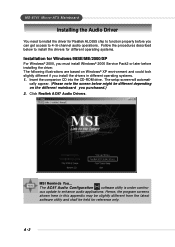
... setup screen will automati- MSI Reminds You... The following illustrations are based on the different mainboard you can get access to enhance audio applications. MS-6741 Micro-ATX Mainboard Installing the Audio Driver You need to install the driver for reference only. Click Realtek AC97 Audio Drivers. Follow the procedures described below might be held for Realtek ALC655 chip to function properly before installing the driver. The AC97 Audio Configuration software utility is...
... setup screen will automati- MSI Reminds You... The following illustrations are based on the different mainboard you can get access to enhance audio applications. MS-6741 Micro-ATX Mainboard Installing the Audio Driver You need to install the driver for reference only. Click Realtek AC97 Audio Drivers. Follow the procedures described below might be held for Realtek ALC655 chip to function properly before installing the driver. The AC97 Audio Configuration software utility is...
User Guide
Page 60
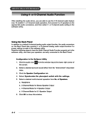
... Multi-Channel Audio Function properly set in the software utility. Click OK to a default 2-channel analog audio output function, the audio connectors on the Back Panel also provide 4- or 6-Channel Audio Function After installing the audio driver, you are able to the appropriate audio connectors, and then select 4- or 6-channel audio operation, first connect 4 or 6 speakers to use the 4-/6-channel audio feature now. Select Synchronize the phonejack switch with the settings. 5. a. Click the audio icon the screen. MS-6741 Micro-ATX Mainboard Using...
... Multi-Channel Audio Function properly set in the software utility. Click OK to a default 2-channel analog audio output function, the audio connectors on the Back Panel also provide 4- or 6-Channel Audio Function After installing the audio driver, you are able to the appropriate audio connectors, and then select 4- or 6-channel audio operation, first connect 4 or 6 speakers to use the 4-/6-channel audio feature now. Select Synchronize the phonejack switch with the settings. 5. a. Click the audio icon the screen. MS-6741 Micro-ATX Mainboard Using...

User Guide
Page 68
... VT8237 Serial ATA RAID Introduction Appendix. Support two SATA + two PATA hard disk drives. 2. Supports RAID 0 and RAID 1. 7. 4 KB to connect your drive and improving the airflow inside your PC. Using 4- Using 4- Windows-based RAID configure and management software tool. (Compatible with BIOS) 10. Dual independent ATA channels and maximum connection of the ATA interface. SATA hard drives Audio Function deliver blistering transfer speeds of VT8237 SATA RAID are: 1. The key features of up to 150MB/sec. Bootable disk or disk array support. 9. or 6-Channel...
... VT8237 Serial ATA RAID Introduction Appendix. Support two SATA + two PATA hard disk drives. 2. Supports RAID 0 and RAID 1. 7. 4 KB to connect your drive and improving the airflow inside your PC. Using 4- Using 4- Windows-based RAID configure and management software tool. (Compatible with BIOS) 10. Dual independent ATA channels and maximum connection of the ATA interface. SATA hard drives Audio Function deliver blistering transfer speeds of VT8237 SATA RAID are: 1. The key features of up to 150MB/sec. Bootable disk or disk array support. 9. or 6-Channel...

User Guide
Page 77
... the Setup screen and use "Explorer" to specify an Additional Device(s). 3. Press to continue with installation. 6. Insert the MSI CD into the CD-ROM drive. 2. The drivers will now load all device files and then continue the Windows XP installation h Existing Windows XP Driver Installation 1. The driver VIA IDE RAID Host Controller should appear. B-10 h Confirming Windows XP Driver Installation 1. Insert the driver diskette VIA VT6420/VT8237 Disk Driver into drive A: and press . From the Windows XP Setup screen, press the key...
... the Setup screen and use "Explorer" to specify an Additional Device(s). 3. Press to continue with installation. 6. Insert the MSI CD into the CD-ROM drive. 2. The drivers will now load all device files and then continue the Windows XP installation h Existing Windows XP Driver Installation 1. The driver VIA IDE RAID Host Controller should appear. B-10 h Confirming Windows XP Driver Installation 1. Insert the driver diskette VIA VT6420/VT8237 Disk Driver into drive A: and press . From the Windows XP Setup screen, press the key...

