
User Guide
Page 4
... a residential installation. FCC-B Radio Frequency Interference Statement This equipment has been tested and found to comply with the limits for help. Micro-Star International MS-7520 This device complies with Part 15 of the FCC Rules. However, there is encouraged to try to correct the interference by the party responsible for...
... a residential installation. FCC-B Radio Frequency Interference Statement This equipment has been tested and found to comply with the limits for help. Micro-Star International MS-7520 This device complies with Part 15 of the FCC Rules. However, there is encouraged to try to correct the interference by the party responsible for...

User Guide
Page 10
Getting Started Chapter 1 Getting Started Thank you for optimal system ef ficiency. The Eclipse mainboard is based on Intel® X58 & ICH10R chipsets for choosing the Eclipse (MS-7520 v1.X) ATX mainboard. Designed to fit the advanced Intel® i7 LGA1366 processor, the Eclipse delivers a high performance and professional desktop platform solution. 1-1
Getting Started Chapter 1 Getting Started Thank you for optimal system ef ficiency. The Eclipse mainboard is based on Intel® X58 & ICH10R chipsets for choosing the Eclipse (MS-7520 v1.X) ATX mainboard. Designed to fit the advanced Intel® i7 LGA1366 processor, the Eclipse delivers a high performance and professional desktop platform solution. 1-1

User Guide
Page 11
... - 6 DDR3 DIMMs support DDR3 1333/ 1066/ 800 DRAM speed (Memory size 24GB Max) - t w / index. Supports storage and data transfers at up to 3 Gb/s RAID - MS-7520 Mainboard Mainboard Specifications Processor Support - php?func =c puform 2) Supported QPI - Supports x8/ x16 data lines per DIMM - c om . Supports 2 PCIE LAN 10/100/1000 Fast...
... - 6 DDR3 DIMMs support DDR3 1333/ 1066/ 800 DRAM speed (Memory size 24GB Max) - t w / index. Supports storage and data transfers at up to 3 Gb/s RAID - MS-7520 Mainboard Mainboard Specifications Processor Support - php?func =c puform 2) Supported QPI - Supports x8/ x16 data lines per DIMM - c om . Supports 2 PCIE LAN 10/100/1000 Fast...

User Guide
Page 13
JPWR1 MS-7520 Mainboard Mainboard Layout JPWR2 Top : mouse Botto m: keyboard Top: USB por ts Botto m: 1394 port eSATA por ts CP U FA N C L R_ C OM S 1 Top: LAN Jack2 ... ICH10R J SM B1 S Y SFA N 3 BATT + JCI1 SATA5_6 SATA2_4 JMB322 SATA7 SATA8 SYSFAN2 I/O Chip JMB363 JUS B1 JMB322 JDLED2 SATA9 SATA10 IDE1 JCOM1 JTPM 1JFP2 JFP1 Eclipse (MS-7520 v1.X) ATX Mainboard SATA1 _3 1-4
JPWR1 MS-7520 Mainboard Mainboard Layout JPWR2 Top : mouse Botto m: keyboard Top: USB por ts Botto m: 1394 port eSATA por ts CP U FA N C L R_ C OM S 1 Top: LAN Jack2 ... ICH10R J SM B1 S Y SFA N 3 BATT + JCI1 SATA5_6 SATA2_4 JMB322 SATA7 SATA8 SYSFAN2 I/O Chip JMB363 JUS B1 JMB322 JDLED2 SATA9 SATA10 IDE1 JCOM1 JTPM 1JFP2 JFP1 Eclipse (MS-7520 v1.X) ATX Mainboard SATA1 _3 1-4

User Guide
Page 19
..., make sure the CPU has a cooler attached on it to protect the socket pin. W rong installation will cause the damage of the CPU base. MS-7520 Mainboard CPU & Cooler Installation W hen you install CPU, always cover it to protect the contack from the lever hinge side (as the arrow shows). 4. Follow...
..., make sure the CPU has a cooler attached on it to protect the socket pin. W rong installation will cause the damage of the CPU base. MS-7520 Mainboard CPU & Cooler Installation W hen you install CPU, always cover it to protect the contack from the lever hinge side (as the arrow shows). 4. Follow...

User Guide
Page 21
MS-7520 Mainboard 9. Mainboard locking switch Hook Important 1. The appearance of the mainboard. 10. Turn over the mainboard to avoid damaging. 3. Align the holes on the model ...
MS-7520 Mainboard 9. Mainboard locking switch Hook Important 1. The appearance of the mainboard. 10. Turn over the mainboard to avoid damaging. 3. Align the holes on the model ...

User Guide
Page 23
MS-7520 Mainboard Three-Channel mode In Three-Channel mode, the memory modules can enhance the best system performance. W hen you have three or more memory modules, ...
MS-7520 Mainboard Three-Channel mode In Three-Channel mode, the memory modules can enhance the best system performance. W hen you have three or more memory modules, ...

User Guide
Page 25
... slot will automatically close when the memory module is properly seated. Manually check if the memory module has been locked in the right orientation. 2. MS-7520 Mainboard Installing Memory Modules 1. Volt Notch 2-10 The memory module has only one notch on the memory module is properly inserted in the DIMM slot...
... slot will automatically close when the memory module is properly seated. Manually check if the memory module has been locked in the right orientation. 2. MS-7520 Mainboard Installing Memory Modules 1. Volt Notch 2-10 The memory module has only one notch on the memory module is properly inserted in the DIMM slot...

User Guide
Page 29
MS-7520 Mainboard Vendor TAKEMS Model TMS1GB364D081-107EQ (With iron case) Bufaullo D3/1066-2G (Micron D9GTR) Crucial CT25664BA1067.16SFD (Micron D9JNL) HYNIX HMT125U6AFP8C-G7N0 (Hynix H5TQ1G83AFP-...
MS-7520 Mainboard Vendor TAKEMS Model TMS1GB364D081-107EQ (With iron case) Bufaullo D3/1066-2G (Micron D9GTR) Crucial CT25664BA1067.16SFD (Micron D9JNL) HYNIX HMT125U6AFP8C-G7N0 (Hynix H5TQ1G83AFP-...

User Guide
Page 31
... 18A. 2-16 To connect the ATX 24-pin power supply, make sure the plug of the power supply is highly recommended for system stability. 3. MS-7520 Mainboard Power Supply ATX 24-Pin Power Connector: JPWR1 This connector allows you to ensure stable operation of the mainboard. 2.
... 18A. 2-16 To connect the ATX 24-pin power supply, make sure the plug of the power supply is highly recommended for system stability. 3. MS-7520 Mainboard Power Supply ATX 24-Pin Power Connector: JPWR1 This connector allows you to ensure stable operation of the mainboard. 2.

User Guide
Page 33
Off 10 Mbit/sec data rate is communicating with another computer on the LAN. On (brighter & pulsing) The computer is selected. On 1000 Mbit/sec data rate is established. MS-7520 Mainboard LAN The standard RJ-45 LAN jack is for connection Yellow to it. On (steady state) LAN link is selected. 2-18 You can connect a network cable to the Local Area Network (LAN). Green / Orange LED Color Left Yellow Green Right Orange LED State Condition Off LAN link is selected. On 100 Mbit/sec data rate is not established.
Off 10 Mbit/sec data rate is communicating with another computer on the LAN. On (brighter & pulsing) The computer is selected. On 1000 Mbit/sec data rate is established. MS-7520 Mainboard LAN The standard RJ-45 LAN jack is for connection Yellow to it. On (steady state) LAN link is selected. 2-18 You can connect a network cable to the Local Area Network (LAN). Green / Orange LED Color Left Yellow Green Right Orange LED State Condition Off LAN link is selected. On 100 Mbit/sec data rate is not established.

User Guide
Page 35
...). 2-20 Please do not fold the Serial ATA cable into 90-degree angle. Please always use the Intel default Black SATA connectors (SATA1~6) fir s t. 3. MS-7520 Mainboard Serial ATA Connector: SATA1~10 This connector is a high-speed Serial ATA interface port. Otherwise, data loss may occur during transmission. 2. Each connector can...
...). 2-20 Please do not fold the Serial ATA cable into 90-degree angle. Please always use the Intel default Black SATA connectors (SATA1~6) fir s t. 3. MS-7520 Mainboard Serial ATA Connector: SATA1~10 This connector is a high-speed Serial ATA interface port. Otherwise, data loss may occur during transmission. 2. Each connector can...

User Guide
Page 37
... front panel switches and LEDs. The JFP1 is a 16550A high speed communication port that sends/receives 16 bytes FIFOs. You can attach a serial device. MS-7520 Mainboard Front Panel Connectors: JFP1, JFP2 These connectors are for electrical connection to GND Reserved.
... front panel switches and LEDs. The JFP1 is a 16550A high speed communication port that sends/receives 16 bytes FIFOs. You can attach a serial device. MS-7520 Mainboard Front Panel Connectors: JFP1, JFP2 These connectors are for electrical connection to GND Reserved.

User Guide
Page 39
... the GreenPower Genie manual for connecting high-speed USB interface peripherals such as USB HDD, digital cameras, MP3 players, printers, modems and the like. MS-7520 Mainboard Front USB Connector: JUSB1/ JUSB2 These connectors, compliant with Intel® I/O Connectivity Design Guide, is ideal for more details and usages. 2 1 JSM B1 2-24...
... the GreenPower Genie manual for connecting high-speed USB interface peripherals such as USB HDD, digital cameras, MP3 players, printers, modems and the like. MS-7520 Mainboard Front USB Connector: JUSB1/ JUSB2 These connectors, compliant with Intel® I/O Connectivity Design Guide, is ideal for more details and usages. 2 1 JSM B1 2-24...

User Guide
Page 41
... (PCI_E5) Important The mainboard supports ATI CrossFireXTM technology with two Black PCIEx16 slots and 3-way CrossFireXTM with all the three PCIE x16 slots. 2-26 MS-7520 Mainboard Slots PCI (Peripheral Component Interconnect) Express Slot The PCI Express slot supports the PCI Express interface expansion card. The PCI Express 2.0 x4 supports up...
... (PCI_E5) Important The mainboard supports ATI CrossFireXTM technology with two Black PCIEx16 slots and 3-way CrossFireXTM with all the three PCIE x16 slots. 2-26 MS-7520 Mainboard Slots PCI (Peripheral Component Interconnect) Express Slot The PCI Express slot supports the PCI Express interface expansion card. The PCI Express 2.0 x4 supports up...

User Guide
Page 43
... graphics card manual from the view drop menu. There is a setting in Catalyst™ Control Center: Select the Advanced View from the manufacturer. 2-28 MS-7520 Mainboard 3.W hen all of the hardware and software has been properly set up and installed, reboot the system. The following aspect appears in the Catalyst...
... graphics card manual from the view drop menu. There is a setting in Catalyst™ Control Center: Select the Advanced View from the manufacturer. 2-28 MS-7520 Mainboard 3.W hen all of the hardware and software has been properly set up and installed, reboot the system. The following aspect appears in the Catalyst...

User Guide
Page 45
MS-7520 Mainboard Switch Hardware Overclock Base clock Switch: CPU_CLK1 You can also overclock by changing this switch. ON 123 133 MHz (default) ON 123 166 MHz ...
MS-7520 Mainboard Switch Hardware Overclock Base clock Switch: CPU_CLK1 You can also overclock by changing this switch. ON 123 133 MHz (default) ON 123 166 MHz ...
User Guide
Page 47
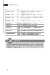
... system is in standby (S3/S4/S5 ) status. Lights blue when the PCI Slot is functional. Lights blue when the PCIE Slot is functional. MS-7520 Mainboard N am e CPU Phase LEDs QPI Phase LEDs IOH Phase LEDs DDR Phase LEDs PCI E LEDs PCI LEDs Power LED Standby LED DIMM Warning LED...
... system is in standby (S3/S4/S5 ) status. Lights blue when the PCI Slot is functional. Lights blue when the PCIE Slot is functional. MS-7520 Mainboard N am e CPU Phase LEDs QPI Phase LEDs IOH Phase LEDs DDR Phase LEDs PCI E LEDs PCI LEDs Power LED Standby LED DIMM Warning LED...

User Guide
Page 49
.... 3-2 It is the BIOS version. Press DEL to enter SETUP If the message disappears before you respond and you still wish to enter Setup. MS-7520 Mainboard Entering Setup Power on the screen, press key to enter Setup, restart the system by simultaneously pressing , , and keys. You may be slightly different...
.... 3-2 It is the BIOS version. Press DEL to enter SETUP If the message disappears before you respond and you still wish to enter Setup. MS-7520 Mainboard Entering Setup Power on the screen, press key to enter Setup, restart the system by simultaneously pressing , , and keys. You may be slightly different...

User Guide
Page 51
MS-7520 Mainboard The Main Menu Standard CMOS Features Use this menu to specify the power phase. H/W Monitor This entry shows your settings for frequency/voltage control ...
MS-7520 Mainboard The Main Menu Standard CMOS Features Use this menu to specify the power phase. H/W Monitor This entry shows your settings for frequency/voltage control ...