User Manual
Page 1
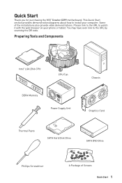
Some of Screws Quick Start 1 Preparing Tools and Components Intel® LGA 2066 CPU CPU Fan DDR4 Memory Power Supply Unit Chassis Graphics Card Thermal Paste SATA Hard Disk Drive SATA DVD Drive Phillips Screwdriver A Package of the installations also provide video demonstrations. You may ... tablet. This Quick Start section provides demonstration diagrams about how to the URL by scanning the QR code. Quick Start Thank you for purchasing the MSI® Creator X299 motherboard. Please link to the URL to watch it with the web browser on your computer.
Some of Screws Quick Start 1 Preparing Tools and Components Intel® LGA 2066 CPU CPU Fan DDR4 Memory Power Supply Unit Chassis Graphics Card Thermal Paste SATA Hard Disk Drive SATA DVD Drive Phillips Screwdriver A Package of the installations also provide video demonstrations. You may ... tablet. This Quick Start section provides demonstration diagrams about how to the URL by scanning the QR code. Quick Start Thank you for purchasing the MSI® Creator X299 motherboard. Please link to the URL to watch it with the web browser on your computer.
User Manual
Page 2
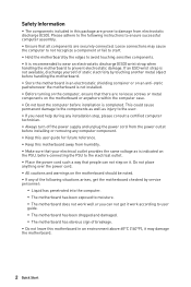
...on the PSU, before connecting the PSU to the electrical outlet. ∙∙Place the power cord such a way that there are securely connected. Do not place anything over the power cord. ∙∙All cautions and warnings on the motherboard should be noted. ∙&#...you need help during any installation step, please consult a certified computer technician. ∙∙Always turn off the power supply and unplug the power cord from the power outlet before installing or removing any of the following instructions to ensure successful computer assembly. ∙∙Ensure that all...
...on the PSU, before connecting the PSU to the electrical outlet. ∙∙Place the power cord such a way that there are securely connected. Do not place anything over the power cord. ∙∙All cautions and warnings on the motherboard should be noted. ∙&#...you need help during any installation step, please consult a certified computer technician. ∙∙Always turn off the power supply and unplug the power cord from the power outlet before installing or removing any of the following instructions to ensure successful computer assembly. ∙∙Ensure that all...
User Manual
Page 33
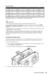
...To install SLI graphics cards: 1. Overview of the graphics cards. Installing SLI graphics cards For power supply recommendations for SLI configurations, please refer to the user guide of your computer and disconnect the power cord, install two graphics cards into the PCI_E1 and PCI_E3 slots. 2. for 28-lane CPU... turn off your graphics card to make sure you need to use a tool such as MSI Gaming Series Graphics Card Bolster to support its weight to check for any necessary additional hardware or software changes. Turn off the power supply and unplug the power supply power cable from the...
...To install SLI graphics cards: 1. Overview of the graphics cards. Installing SLI graphics cards For power supply recommendations for SLI configurations, please refer to the user guide of your computer and disconnect the power cord, install two graphics cards into the PCI_E1 and PCI_E3 slots. 2. for 28-lane CPU... turn off your graphics card to make sure you need to use a tool such as MSI Gaming Series Graphics Card Bolster to support its weight to check for any necessary additional hardware or software changes. Turn off the power supply and unplug the power supply power cable from the...

User Manual
Page 39
Insert the M.2 XPANDER-AERO card into the PCI_E1 or PCI_E3 slot. 10. Using the supplied HDD LED cable to the power supply. 12. Connect the PCIE_PWR1 to connect the JMB connector and JFP1's HDD pins (pin 1 & pin3). 11 PCIE_PWR1 JCASE + JMB + 12 JFP1 2 10 1 9 + - 13 HDD LED Overview of Components 39 Use the screw to the JCASE connector. 13. Connect the case's HDD LED cable to secure the M.2 XPANDER-AERO card. 10 9 PCI_E1/ PCI_E3 11. 9.
Insert the M.2 XPANDER-AERO card into the PCI_E1 or PCI_E3 slot. 10. Using the supplied HDD LED cable to the power supply. 12. Connect the PCIE_PWR1 to connect the JMB connector and JFP1's HDD pins (pin 1 & pin3). 11 PCIE_PWR1 JCASE + JMB + 12 JFP1 2 10 1 9 + - 13 HDD LED Overview of Components 39 Use the screw to the JCASE connector. 13. Connect the case's HDD LED cable to secure the M.2 XPANDER-AERO card. 10 9 PCI_E1/ PCI_E3 11. 9.

User Manual
Page 41
... These connectors allow you to connect an ATX power supply. 8 5 CPU_PWR1~3 4 1 1 Ground 5 2 Ground 6 3 Ground 7 4 Ground 8 +12V +12V +12V +12V 1 +3.3V 13 2 +3.3V 14 3 Ground 15 12 24 4 +5V 16 5 Ground 17 6 +5V 18 ATX_PWR1 7 Ground ... -12V Ground PS-ON# Ground Ground Ground Res +5V +5V +5V Ground 1 PCIE_PWR1 +12V 3 Ground 1 2 Ground 4 +5V ⚠⚠Important Make sure that all the power cables are securely connected to a proper ATX power supply to ensure stable operation of Components 41 Overview of the motherboard.
... These connectors allow you to connect an ATX power supply. 8 5 CPU_PWR1~3 4 1 1 Ground 5 2 Ground 6 3 Ground 7 4 Ground 8 +12V +12V +12V +12V 1 +3.3V 13 2 +3.3V 14 3 Ground 15 12 24 4 +5V 16 5 Ground 17 6 +5V 18 ATX_PWR1 7 Ground ... -12V Ground PS-ON# Ground Ground Ground Res +5V +5V +5V Ground 1 PCIE_PWR1 +12V 3 Ground 1 2 Ground 4 +5V ⚠⚠Important Make sure that all the power cables are securely connected to a proper ATX power supply to ensure stable operation of Components 41 Overview of the motherboard.

User Manual
Page 52
... 2 meters continuous 5050 RGB LED strips (12V/G/R/B) with the maximum power rating of 3A (12V). ∙∙Always turn off the power supply and unplug the power cord from the power outlet before installing or removing the RGB LED strip. ∙∙Please use MSI's software to control the extended LED strip. 52 Overview of Components
... 2 meters continuous 5050 RGB LED strips (12V/G/R/B) with the maximum power rating of 3A (12V). ∙∙Always turn off the power supply and unplug the power cord from the power outlet before installing or removing the RGB LED strip. ∙∙Please use MSI's software to control the extended LED strip. 52 Overview of Components

User Manual
Page 53
... ∙∙The JRAINBOW connector supports up to 200 LEDs. ∙∙Always turn off the power supply and unplug the power cord from the power outlet before installing or removing the RGB LED strip. ∙∙Please use MSI's software to control the extended LED strip. In the case of 20% brightness, the connector.... JRAINBOW1~2: Addressable RGB LED connectors The JRAINBOW connectors allow you to 75 LEDs WS2812B Individually Addressable RGB LED strips (5V/Data/Ground) with the maximum power rating of 3A (5V).
... ∙∙The JRAINBOW connector supports up to 200 LEDs. ∙∙Always turn off the power supply and unplug the power cord from the power outlet before installing or removing the RGB LED strip. ∙∙Please use MSI's software to control the extended LED strip. In the case of 20% brightness, the connector.... JRAINBOW1~2: Addressable RGB LED connectors The JRAINBOW connectors allow you to 75 LEDs WS2812B Individually Addressable RGB LED strips (5V/Data/Ground) with the maximum power rating of 3A (5V).
User Manual
Page 64
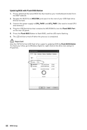
... your motherboard model from the MSI® website. 2. Rename the BIOS file to MSI.ROM, and save it to the root of your drive, go to Windows Explorer, right click on the rear I/O panel. 5. Press the Flash BIOS Button to install CPU and memory.) 4. Connect the power supply to CPU_PWR1 and ATX_PWR1. (...9888;Important Only the FAT32 format USB flash drive supports updating BIOS by Flash BIOS Button. Please download the latest BIOS file that contains the MSI.ROM file into the Flash BIOS Port on the drive icon and go to Properties. 64 BIOS Setup Updating BIOS with Flash BIOS Button ...
... your motherboard model from the MSI® website. 2. Rename the BIOS file to MSI.ROM, and save it to the root of your drive, go to Windows Explorer, right click on the rear I/O panel. 5. Press the Flash BIOS Button to install CPU and memory.) 4. Connect the power supply to CPU_PWR1 and ATX_PWR1. (...9888;Important Only the FAT32 format USB flash drive supports updating BIOS by Flash BIOS Button. Please download the latest BIOS file that contains the MSI.ROM file into the Flash BIOS Port on the drive icon and go to Properties. 64 BIOS Setup Updating BIOS with Flash BIOS Button ...
User Manual
Page 100
... ports on the motherboard rear IO panel. ∙∙Remove secondary speakers/ headphones, HDMI cables, USB audio devices. ∙∙Test with another known working power supply of equal or greater wattage. There is no network ∙∙Make sure the network chipset driver has been installed. ∙∙Verify if the...
... ports on the motherboard rear IO panel. ∙∙Remove secondary speakers/ headphones, HDMI cables, USB audio devices. ∙∙Test with another known working power supply of equal or greater wattage. There is no network ∙∙Make sure the network chipset driver has been installed. ∙∙Verify if the...

