User Manual
Page 1
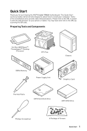
... Paste SATA Hard Disk Drive SATA DVD Drive Phillips Screwdriver A Package of the installations also provide video demonstrations. Quick Start Thank you for purchasing the MSI® Creator TRX40 motherboard. You may have even link to watch it with the web browser on your computer. Some of Screws Quick Start 1
... Paste SATA Hard Disk Drive SATA DVD Drive Phillips Screwdriver A Package of the installations also provide video demonstrations. Quick Start Thank you for purchasing the MSI® Creator TRX40 motherboard. You may have even link to watch it with the web browser on your computer. Some of Screws Quick Start 1
User Manual
Page 2
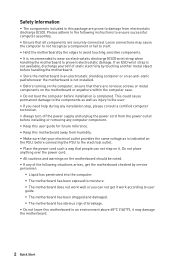
... the edges to avoid touching sensitive components. ∙∙It is recommended to wear an electrostatic discharge (ESD) wrist strap when handling the motherboard to the electrical outlet. ∙∙Place the power cord such a way that people can not get it . Do not place anything.... If an ESD wrist strap is indicated on the PSU, before connecting the PSU to prevent electrostatic damage. Loose connections may damage the motherboard. 2 Quick Start This could cause permanent damage to the components as well as is not available, discharge yourself of breakage. ∙∙...
... the edges to avoid touching sensitive components. ∙∙It is recommended to wear an electrostatic discharge (ESD) wrist strap when handling the motherboard to the electrical outlet. ∙∙Place the power cord such a way that people can not get it . Do not place anything.... If an ESD wrist strap is indicated on the PSU, before connecting the PSU to prevent electrostatic damage. Loose connections may damage the motherboard. 2 Quick Start This could cause permanent damage to the components as well as is not available, discharge yourself of breakage. ∙∙...
User Manual
Page 6
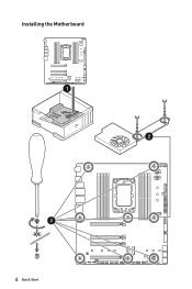
Installing the Motherboard 1 2 3 6 Quick Start
Installing the Motherboard 1 2 3 6 Quick Start
User Manual
Page 12
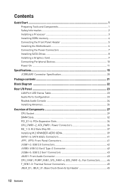
Contents Quick Start...1 Preparing Tools and Components 1 Safety Information 2 Installing a Processor 3 Installing DDR4 memory 4 Connecting the Front Panel Header 5 Installing the Motherboard 6 Connecting the Power Connectors 7 Installing SATA Drives 8 Installing a Graphics Card 9 Connecting Peripheral Devices 10 Power On...11 Specifications...15 JCORSAIR1 Connector Specification 20 Package contents ...
Contents Quick Start...1 Preparing Tools and Components 1 Safety Information 2 Installing a Processor 3 Installing DDR4 memory 4 Connecting the Front Panel Header 5 Installing the Motherboard 6 Connecting the Power Connectors 7 Installing SATA Drives 8 Installing a Graphics Card 9 Connecting Peripheral Devices 10 Power On...11 Specifications...15 JCORSAIR1 Connector Specification 20 Package contents ...
User Manual
Page 21
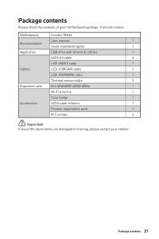
Package contents 21 Package contents Please check the contents of the above items are damaged or missing, please contact your motherboard package. It should contain: Motherboard Creator TRX40 User manual 1 Documentation Quick installation guide 1 Application USB drive with drivers & utilities 1 SATA 6G cable 4 LED JRGB Y cable 1 Cables LED JCORSAIR cable 1 LED JRAINBOW cable 1 ...
Package contents 21 Package contents Please check the contents of the above items are damaged or missing, please contact your motherboard package. It should contain: Motherboard Creator TRX40 User manual 1 Documentation Quick installation guide 1 Application USB drive with drivers & utilities 1 SATA 6G cable 4 LED JRGB Y cable 1 Cables LED JCORSAIR cable 1 LED JRAINBOW cable 1 ...
User Manual
Page 31
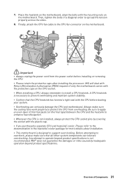
A CPU heatsink is designed to install a CPU heatsink. MSI will deal with Return Merchandise Authorization (RMA) requests if only the motherboard comes with the mounting nuts on the motherboard. Finally, attach the CPU fan cable to the CPU fan connector on the CPU socket. ∙∙When ...work properly to prevent overheating and maintain system stability. ∙∙Confirm that all other system components can seriously damage the CPU and motherboard. Always make sure that the CPU heatsink has formed a tight seal with the plastic cap. ∙∙If you purchased a...
A CPU heatsink is designed to install a CPU heatsink. MSI will deal with Return Merchandise Authorization (RMA) requests if only the motherboard comes with the mounting nuts on the motherboard. Finally, attach the CPU fan cable to the CPU fan connector on the CPU socket. ∙∙When ...work properly to prevent overheating and maintain system stability. ∙∙Confirm that all other system components can seriously damage the CPU and motherboard. Always make sure that the CPU heatsink has formed a tight seal with the plastic cap. ∙∙If you purchased a...
User Manual
Page 36
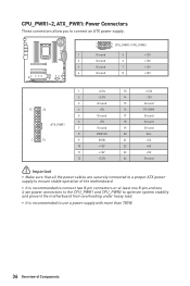
...;⚠Important ∙∙Make sure that all the power cables are securely connected to a proper ATX power supply to ensure stable operation of the motherboard. ∙∙It is recommended to connect two 8-pin connectors or at least one 8-pin and one 4-pin power connectors to the CPU_PWR1 and ...CPU_PWR2 to optimize system stability and prevent the motherboard from overheating under heavy load. ∙∙It is recommended to use a power supply with more than 750W. 36 Overview of Components
...;⚠Important ∙∙Make sure that all the power cables are securely connected to a proper ATX power supply to ensure stable operation of the motherboard. ∙∙It is recommended to connect two 8-pin connectors or at least one 8-pin and one 4-pin power connectors to the CPU_PWR1 and ...CPU_PWR2 to optimize system stability and prevent the motherboard from overheating under heavy load. ∙∙It is recommended to use a power supply with more than 750W. 36 Overview of Components
User Manual
Page 41
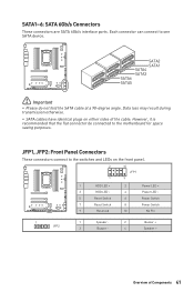
... Power LED + Power LED Power Switch Power Switch No Pin 1 JFP2 1 Speaker - 2 3 Buzzer - 4 Buzzer + Speaker + Overview of the cable. Each connector can connect to the motherboard for space saving purposes. SATA1~6: SATA 6Gb/s Connectors These connectors are SATA 6Gb/s interface ports.
... Power LED + Power LED Power Switch Power Switch No Pin 1 JFP2 1 Speaker - 2 3 Buzzer - 4 Buzzer + Speaker + Overview of the cable. Each connector can connect to the motherboard for space saving purposes. SATA1~6: SATA 6Gb/s Connectors These connectors are SATA 6Gb/s interface ports.
User Manual
Page 44
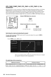
... speed that allow you can switch between PWM mode and DC mode and adjust fan speed in relation to PWM or DC Mode manually. This motherboard can be classified as PWM (Pulse Width Modulation) Mode or DC Mode. Select PWM mode or DC mode There are gradient points of Components CPU_FAN1...
... speed that allow you can switch between PWM mode and DC mode and adjust fan speed in relation to PWM or DC Mode manually. This motherboard can be classified as PWM (Pulse Width Modulation) Mode or DC Mode. Select PWM mode or DC mode There are gradient points of Components CPU_FAN1...
User Manual
Page 46
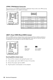
... about 5-10 seconds. 3. Keep Data (default) Clear CMOS/ Reset BIOS Resetting BIOS to clear the CMOS memory. Plug the power cord and power on the motherboard to short JBAT1 for TPM (Trusted Platform Module). Power off the computer and unplug the power cord 2. If you want to clear the system configuration...
... about 5-10 seconds. 3. Keep Data (default) Clear CMOS/ Reset BIOS Resetting BIOS to clear the CMOS memory. Plug the power cord and power on the motherboard to short JBAT1 for TPM (Trusted Platform Module). Power off the computer and unplug the power cord 2. If you want to clear the system configuration...
User Manual
Page 50
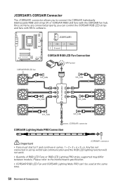
... in series. 1 > 2 > 3 > 4 > 5 > 6. Please refer to connect the CORSAIR Individually Addressable RGB LED strips 5V or CORSAIR RGB LED fans with MSI's software. Once all items are connected properly, you to the motherboard specification. ∙∙CORSAIR RGB LED Fan and CORSAIR Lighting Node PRO can control the CORSAIR RGB LED strips and...
... in series. 1 > 2 > 3 > 4 > 5 > 6. Please refer to connect the CORSAIR Individually Addressable RGB LED strips 5V or CORSAIR RGB LED fans with MSI's software. Once all items are connected properly, you to the motherboard specification. ∙∙CORSAIR RGB LED Fan and CORSAIR Lighting Node PRO can control the CORSAIR RGB LED strips and...
User Manual
Page 52
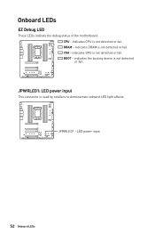
indicates DRAM is used by retailers to demonstrate onboard LED light effects. BOOT - DRAM - JPWRLED1: LED power input This connector is not detected or fail. VGA - JPWRLED1 - LED power input 52 Onboard LEDs indicates GPU is not detected or fail. Onboard LEDs EZ Debug LED These LEDs indicate the debug status of the motherboard. CPU - indicates CPU is not detected or fail. indicates the booting device is not detected or fail.
indicates DRAM is used by retailers to demonstrate onboard LED light effects. BOOT - DRAM - JPWRLED1: LED power input This connector is not detected or fail. VGA - JPWRLED1 - LED power input 52 Onboard LEDs indicates GPU is not detected or fail. Onboard LEDs EZ Debug LED These LEDs indicate the debug status of the motherboard. CPU - indicates CPU is not detected or fail. indicates the booting device is not detected or fail.
User Manual
Page 60
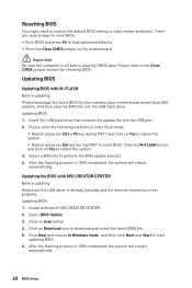
... Del key during POST and click on Download icon to reboot the system. 3. Select a BIOS file to enter BIOS. Install and launch MSI CREATOR CENTER. 2. Please refer the following methods to enter flash mode. ▪▪Reboot and press Ctrl + F5 key during POST to perform...In Windows mode. Please refer to start updating BIOS. 6. Updating BIOS: 1. Insert the USB flash drive that matches your motherboard model from MSI website. Click on the motherboard. ⚠⚠Important Be sure the computer is 100% completed, the system will restart automatically. 60 BIOS Setup After ...
... Del key during POST and click on Download icon to reboot the system. 3. Select a BIOS file to enter BIOS. Install and launch MSI CREATOR CENTER. 2. Please refer the following methods to enter flash mode. ▪▪Reboot and press Ctrl + F5 key during POST to perform...In Windows mode. Please refer to start updating BIOS. 6. Updating BIOS: 1. Insert the USB flash drive that matches your motherboard model from MSI website. Click on the motherboard. ⚠⚠Important Be sure the computer is 100% completed, the system will restart automatically. 60 BIOS Setup After ...
User Manual
Page 61
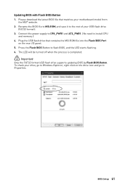
Rename the BIOS file to MSI.ROM, and save it to flash BIOS, and the LED starts flashing. 6. Press the Flash BIOS Button to the root of your USB flash drive (... file into the Flash BIOS Port on the drive icon and go to Windows Explorer, right click on the rear I/O panel. 5. To check your motherboard model from the MSI® website. 2. Updating BIOS with Flash BIOS Button 1. Plug the USB flash drive that matches your drive, go to install CPU and memory...
Rename the BIOS file to MSI.ROM, and save it to flash BIOS, and the LED starts flashing. 6. Press the Flash BIOS Button to the root of your USB flash drive (... file into the Flash BIOS Port on the drive icon and go to Windows Explorer, right click on the rear I/O panel. 5. To check your motherboard model from the MSI® website. 2. Updating BIOS with Flash BIOS Button 1. Plug the USB flash drive that matches your drive, go to install CPU and memory...
User Manual
Page 64
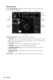
... Setup allows you to adjust the frequency and voltage. allows you to set the speeds of fans and monitor voltages of installed devices on this motherboard. ∙∙ Menu display - Increasing the frequency may get better performance. ▪▪M-FLASH - Advanced Mode Press Setup Mode switch or F7 function key can...
... Setup allows you to adjust the frequency and voltage. allows you to set the speeds of fans and monitor voltages of installed devices on this motherboard. ∙∙ Menu display - Increasing the frequency may get better performance. ▪▪M-FLASH - Advanced Mode Press Setup Mode switch or F7 function key can...
User Manual
Page 65
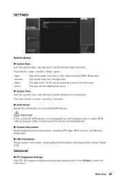
... switch between date elements. The format is not displayed, turn off computer and re-check SATA cable and power cable connections of the device and motherboard. ▶▶System Information Shows detailed system information, including CPU type, BIOS version, and Memory (read only). ▶▶DMI Information Shows system information, desktop...
... switch between date elements. The format is not displayed, turn off computer and re-check SATA cable and power cable connections of the device and motherboard. ▶▶System Information Shows detailed system information, including CPU type, BIOS version, and Memory (read only). ▶▶DMI Information Shows system information, desktop...
User Manual
Page 73
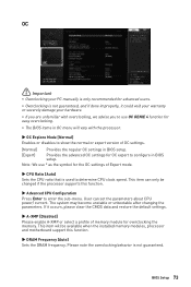
The system may become unstable or unbootable after changing the parameters. User can only be available when the installed memory modules, processor and motherboard support this function. ▶▶Advanced CPU Configuration Press Enter to determine CPU clock speed. Please note the overclocking behavior is used to enter the ...
The system may become unstable or unbootable after changing the parameters. User can only be available when the installed memory modules, processor and motherboard support this function. ▶▶Advanced CPU Configuration Press Enter to determine CPU clock speed. Please note the overclocking behavior is used to enter the ...
User Manual
Page 76
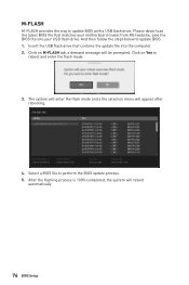
... M-FLASH provides the way to perform the BIOS update process. 5. Please down-load the latest BIOS file that contains the update file into your motherboard model from MSI website, save the BIOS file into the computer. 2. After the flashing process is 100% completed, the system will appear after rebooting. 4. Insert the USB...
... M-FLASH provides the way to perform the BIOS update process. 5. Please down-load the latest BIOS file that contains the update file into your motherboard model from MSI website, save the BIOS file into the computer. 2. After the flashing process is 100% completed, the system will appear after rebooting. 4. Insert the USB...
User Manual
Page 79
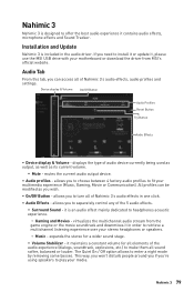
..., Movie or Communication). All profiles can access all of Nahimic 3's audio effects, audio profiles and settings. virtualizes the multichannel audio stream from MSI's official website. expands the stereo for all sound softer, balanced or louder. The Quiet On / Off option allows to play your media...;▪Volume Stabilizer - Nahimic 3 79 Nahimic 3 Nahimic 3 is designed to install it or update it, please use the MSI USB drive with your motherboard or download the driver from the game engine or the movie soundtrack and downmixes it in the audio driver. If you to...
..., Movie or Communication). All profiles can access all of Nahimic 3's audio effects, audio profiles and settings. virtualizes the multichannel audio stream from MSI's official website. expands the stereo for all sound softer, balanced or louder. The Quiet On / Off option allows to play your media...;▪Volume Stabilizer - Nahimic 3 79 Nahimic 3 Nahimic 3 is designed to install it or update it, please use the MSI USB drive with your motherboard or download the driver from the game engine or the movie soundtrack and downmixes it in the audio driver. If you to...
User Manual
Page 87
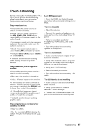
... an electrical outlet securely. ∙∙Check if all ATX power connectors like ATX_PWR1, CPU_PWR1~2 are connected from the power supply to the motherboard. ∙∙Some power supply units have a power button on the rear side, make sure the LAN port LEDs are heard, remove ...speaker or headphone. There is no audio ∙∙Adjust the volume. ∙∙Connect the speakers/headphones to other USB port on the motherboard rear IO panel. ∙∙Remove secondary speakers/ headphones, HDMI cables, USB audio devices. ∙∙Test with another known working power ...
... an electrical outlet securely. ∙∙Check if all ATX power connectors like ATX_PWR1, CPU_PWR1~2 are connected from the power supply to the motherboard. ∙∙Some power supply units have a power button on the rear side, make sure the LAN port LEDs are heard, remove ...speaker or headphone. There is no audio ∙∙Adjust the volume. ∙∙Connect the speakers/headphones to other USB port on the motherboard rear IO panel. ∙∙Remove secondary speakers/ headphones, HDMI cables, USB audio devices. ∙∙Test with another known working power ...


