User Manual
Page 14
... LED ...35 BIOS Setup ...36 Entering BIOS Setup 36 Resetting BIOS...37 Updating BIOS...37 EZ Mode ...38 Advanced Mode ...40 SETTINGS...41 Advanced...41 Boot...46 Security ...47 Save & Exit...48 OC...49 M-FLASH ...52 OC PROFILE ...53 HARDWARE MONITOR 54 Software Description 55 Installing Windows® 7 64-bit/ Windows®10 64-bit 55 Installing Drivers 55 Installing Utilities 55 LIVE UPDATE 6...56 COMMAND CENTER 58 RAMDISK...62 X-BOOST ...63 MSI SMART TOOL 65 MYSTIC LIGHT...67 CPU-Z...68 Troubleshooting...
... LED ...35 BIOS Setup ...36 Entering BIOS Setup 36 Resetting BIOS...37 Updating BIOS...37 EZ Mode ...38 Advanced Mode ...40 SETTINGS...41 Advanced...41 Boot...46 Security ...47 Save & Exit...48 OC...49 M-FLASH ...52 OC PROFILE ...53 HARDWARE MONITOR 54 Software Description 55 Installing Windows® 7 64-bit/ Windows®10 64-bit 55 Installing Drivers 55 Installing Utilities 55 LIVE UPDATE 6...56 COMMAND CENTER 58 RAMDISK...62 X-BOOST ...63 MSI SMART TOOL 65 MYSTIC LIGHT...67 CPU-Z...68 Troubleshooting...
User Manual
Page 16
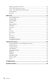
... 1x LAN (RJ45) port y 6x audio jacks y 1x 24-pin ATX main power connector y 1x 8-pin ATX 12V power connector y 4x SATA 6Gb/s connectors y 2x USB 2.0 connectors (support additional 4 USB 2.0 ports) y 2x USB 3.1 Gen1 connectors (support additional 4 USB 3.1 Gen1 ports) y 1x 4-pin CPU fan connector y 1x 4-pin water-pump-fan connector y 4x 4-pin system fan connectors y 1x 4-pin RGB LED strip connector y 1x Serial port connector y 1x Parallel port connector y 1x TPM module connector y 1x Front panel audio connector y 2x System panel connectors y 1x Chassis Intrusion connector y 1x Clear CMOS jumper...
... 1x LAN (RJ45) port y 6x audio jacks y 1x 24-pin ATX main power connector y 1x 8-pin ATX 12V power connector y 4x SATA 6Gb/s connectors y 2x USB 2.0 connectors (support additional 4 USB 2.0 ports) y 2x USB 3.1 Gen1 connectors (support additional 4 USB 3.1 Gen1 ports) y 1x 4-pin CPU fan connector y 1x 4-pin water-pump-fan connector y 4x 4-pin system fan connectors y 1x 4-pin RGB LED strip connector y 1x Serial port connector y 1x Parallel port connector y 1x TPM module connector y 1x Front panel audio connector y 2x System panel connectors y 1x Chassis Intrusion connector y 1x Clear CMOS jumper...

User Manual
Page 35
... LED This LED indicates the CPU's iGPU is not detected and you want to clear the system configuration, set the jumpers to clear the CMOS memory. GPU LED EZ Debug LEDs Overview of key components during booting process. JBAT1: Clear CMOS (Reset BIOS) Jumper There is CMOS memory onboard that is external powered from JBAT1. 4. When an error is occurred, the corresponding LED stays lit until the problem is not detected or fail. Keep Data (default) Clear CMOS/ Reset BIOS Resetting BIOS to short...
... LED This LED indicates the CPU's iGPU is not detected and you want to clear the system configuration, set the jumpers to clear the CMOS memory. GPU LED EZ Debug LEDs Overview of key components during booting process. JBAT1: Clear CMOS (Reset BIOS) Jumper There is CMOS memory onboard that is external powered from JBAT1. 4. When an error is occurred, the corresponding LED stays lit until the problem is not detected or fail. Keep Data (default) Clear CMOS/ Reset BIOS Resetting BIOS to short...
User Manual
Page 37
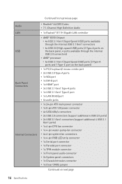
... resetting BIOS. Select BIOS Update. 3. Click on the motherboard. Updating BIOS Updating BIOS with Live Update 6 Before updating: Make sure the LAN driver is already installed and the internet connection is off before clearing CMOS data. Resetting BIOS You might need to restore the default BIOS setting to solve certain problems. There are several ways to reset BIOS: y Go to BIOS and press F6 to start updating BIOS. 6. Updating the BIOS with M-FLASH Before updating: Please download the latest BIOS file that contains the update file into the USB flash drive...
... resetting BIOS. Select BIOS Update. 3. Click on the motherboard. Updating BIOS Updating BIOS with Live Update 6 Before updating: Make sure the LAN driver is already installed and the internet connection is off before clearing CMOS data. Resetting BIOS You might need to restore the default BIOS setting to solve certain problems. There are several ways to reset BIOS: y Go to BIOS and press F6 to start updating BIOS. 6. Updating the BIOS with M-FLASH Before updating: Please download the latest BIOS file that contains the update file into the USB flash drive...
User Manual
Page 38
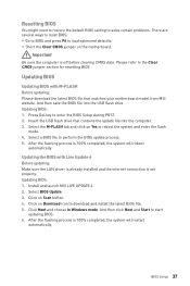
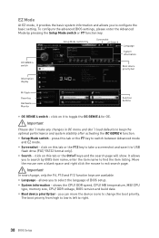
... key to switch between Advanced mode and EZ mode. To configure the advanced BIOS settings, please enter the Advanced Mode by BIOS item name, enter the item name to find the item listing. shows the CPU/ DDR speed, CPU/ MB temperature, MB/ CPU type, memory size, CPU/ DDR voltage, BIOS version and build date. The boot priority from high to low is left to right. 38 BIOS Setup y Screenshot - y Language - y Boot device priority bar - you to select the language of BIOS setup...
... key to switch between Advanced mode and EZ mode. To configure the advanced BIOS settings, please enter the Advanced Mode by BIOS item name, enter the item name to find the item listing. shows the CPU/ DDR speed, CPU/ MB temperature, MB/ CPU type, memory size, CPU/ DDR voltage, BIOS version and build date. The boot priority from high to low is left to right. 38 BIOS Setup y Screenshot - y Language - y Boot device priority bar - you to select the language of BIOS setup...
User Manual
Page 39
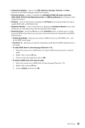
... (Favorite 1~5) 1. Choose a favorite page and click on OK. BIOS Setup 39 y Function buttons - enable or disable the LAN Option ROM, HD audio controller, AHCI, RAID, CPU Fan Fail Warning Control and BIOS Log Review by percentage. SETTINGS, OC...,etc) as the BIOS home page. ƒ Favorite1~5 - allows you to display related information. Right-click or press F2 key. 3. Right-click or press F2 key. 3. Choose Delete and click on OK. ƒ To...
... (Favorite 1~5) 1. Choose a favorite page and click on OK. BIOS Setup 39 y Function buttons - enable or disable the LAN Option ROM, HD audio controller, AHCI, RAID, CPU Fan Fail Warning Control and BIOS Log Review by percentage. SETTINGS, OC...,etc) as the BIOS home page. ƒ Favorite1~5 - allows you to display related information. Right-click or press F2 key. 3. Right-click or press F2 key. 3. Choose Delete and click on OK. ƒ To...
User Manual
Page 40
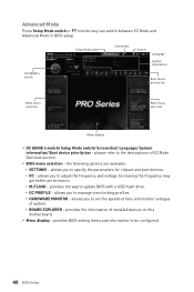
... to set the speeds of fans and monitor voltages of installed devices on this motherboard. y BIOS menu selection - allows you to adjust the frequency and voltage. y Menu display - provides the information of system. ƒ BOARD EXPLORER - the following options are available: ƒ SETTINGS - allows you to manage overclocking profiles. ƒ HARDWARE MONITOR - please refer to update BIOS with a USB flash drive. ƒ OC PROFILE - provides BIOS setting items and information to specify the parameters for chipset and boot devices...
... to set the speeds of fans and monitor voltages of installed devices on this motherboard. y BIOS menu selection - allows you to adjust the frequency and voltage. y Menu display - provides the information of system. ƒ BOARD EXPLORER - the following options are available: ƒ SETTINGS - allows you to manage overclocking profiles. ƒ HARDWARE MONITOR - please refer to update BIOS with a USB flash drive. ƒ OC PROFILE - provides BIOS setting items and information to specify the parameters for chipset and boot devices...
User Manual
Page 42
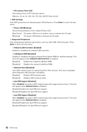
... boot support. fPower LED [Blinking] Sets shining behaviors of onboard power LED behaviors. fIpv6 PXE Support [Enabled] When Enabled, the system UEFI network stack will support Ipv4 protocol. This item is available when Onboard LAN Controller is enabled. [Enabled] Enables the Ipv6 PXE boot support. [Disabled] Disables the Ipv6 PXE boot support. 42 BIOS Setup fPCI Latency Timer [32] Sets latency timer of PCI interface device. [Options: 32, 64, 96, 128, 160, 192, 224, 248 PCI Bus clocks] f ACPI Settings Sets ACPI parameters of the onboard Power LED. [Dual Color] The power LED turns...
... boot support. fPower LED [Blinking] Sets shining behaviors of onboard power LED behaviors. fIpv6 PXE Support [Enabled] When Enabled, the system UEFI network stack will support Ipv4 protocol. This item is available when Onboard LAN Controller is enabled. [Enabled] Enables the Ipv6 PXE boot support. [Disabled] Disables the Ipv6 PXE boot support. 42 BIOS Setup fPCI Latency Timer [32] Sets latency timer of PCI interface device. [Options: 32, 64, 96, 128, 160, 192, 224, 248 PCI Bus clocks] f ACPI Settings Sets ACPI parameters of the onboard Power LED. [Dual Color] The power LED turns...
User Manual
Page 43
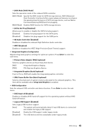
... primary boot device. [IGD] Integrated Graphics Display. [PEG] PCI-Express Graphics Device. fHD Audio Controller [Enabled] Enables or disables the onboard High Definition Audio controller. This item will be available when Integrated Graphics is connected and enable the legacy USB support. [Enabled] Enable the USB support under legacy mode. [Disabled] The USB devices will be unavailable under legacy mode. BIOS Setup 43 f Integrated Graphics Configuration Adjusts integrated graphics settings for the SATA ports. fLegacy USB Support [Enabled] Sets Legacy USB...
... primary boot device. [IGD] Integrated Graphics Display. [PEG] PCI-Express Graphics Device. fHD Audio Controller [Enabled] Enables or disables the onboard High Definition Audio controller. This item will be available when Integrated Graphics is connected and enable the legacy USB support. [Enabled] Enable the USB support under legacy mode. [Disabled] The USB devices will be unavailable under legacy mode. BIOS Setup 43 f Integrated Graphics Configuration Adjusts integrated graphics settings for the SATA ports. fLegacy USB Support [Enabled] Sets Legacy USB...
User Manual
Page 44
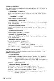
... Printer Mode] Printer port mode [SPP] Standard Parallel Port mode [EPP-1.9 and SPP Mode] Enhanced Parallel Port-1.9 mode + Standard Parallel Port mode. Press Enter to enter the sub-menu. fParallel (LPT) Port Configuration Sets detailed configuration of parallel port (LPT/ LPTE). Press Enter to enter the submenu. Press Enter to the previous state (power on/ power off state after restoring AC power. [Power On] Boot up by USB, PCI and PCIe devices. [Disabled] Disables this function. fParallel (LPT) Port Settings [Auto] Sets parallel port...
... Printer Mode] Printer port mode [SPP] Standard Parallel Port mode [EPP-1.9 and SPP Mode] Enhanced Parallel Port-1.9 mode + Standard Parallel Port mode. Press Enter to enter the sub-menu. fParallel (LPT) Port Configuration Sets detailed configuration of parallel port (LPT/ LPTE). Press Enter to enter the submenu. Press Enter to the previous state (power on/ power off state after restoring AC power. [Power On] Boot up by USB, PCI and PCIe devices. [Disabled] Disables this function. fParallel (LPT) Port Settings [Auto] Sets parallel port...
User Manual
Page 45
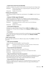
... installed PCI/ PCI-E expansion cards, integrated LAN controllers or USB devices which are supported by BIOS or operating system. [BIOS] Activates the following items, set to select the date & time settings). fSecure Boot Sets the Windows secure boot to boot up when detecting abnormal voltage input. [Enabled] Protect the system from unexpected power operating and remain the shut down status. [Disabled] Disables this item, make sure all installed devices & utilities (hardware & software) should meet the Windows requirement. [Disabled] Disables this...
... installed PCI/ PCI-E expansion cards, integrated LAN controllers or USB devices which are supported by BIOS or operating system. [BIOS] Activates the following items, set to select the date & time settings). fSecure Boot Sets the Windows secure boot to boot up when detecting abnormal voltage input. [Enabled] Protect the system from unexpected power operating and remain the shut down status. [Disabled] Disables this item, make sure all installed devices & utilities (hardware & software) should meet the Windows requirement. [Disabled] Disables this...
User Manual
Page 46
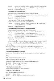
... of PCI/ PCIe device is detected. Boot Sets the sequence of Help information block. [Unlock] Sliding effect. [Lock] Fix the Help information block on the screen. 46 BIOS Setup f Bootup NumLock State [On] Select the keyboard NumLock state upon bootup. fResume From S3/S4/S5 by PS/2 Keyboard [Disabled] Enables or disables the system wake up by USB device. [Enabled] Enables the system to be awakened from sleep state...
... of PCI/ PCIe device is detected. Boot Sets the sequence of Help information block. [Unlock] Sliding effect. [Lock] Fix the Help information block on the screen. 46 BIOS Setup f Bootup NumLock State [On] Select the keyboard NumLock state upon bootup. fResume From S3/S4/S5 by PS/2 Keyboard [Disabled] Enables or disables the system wake up by USB device. [Enabled] Enables the system to be awakened from sleep state...
User Manual
Page 47
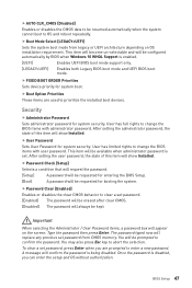
... installation requirement. f Password Clear [Enabled] Enables or disables the clear CMOS behavior to confirm the password. Type the password then press Enter. You will always be available when administrator password is enabled. [UEFI] Enables UEFI BIOS boot mode support only. [LEGACY+UEFI] Enables both Legacy BIOS boot mode and UEFI BIOS boot mode. This item will become un-selectable and will be kept. User has full rights to change the BIOS items with user password. f User Password Sets User Password for system boot. User has limited rights to change the BIOS...
... installation requirement. f Password Clear [Enabled] Enables or disables the clear CMOS behavior to confirm the password. Type the password then press Enter. You will always be available when administrator password is enabled. [UEFI] Enables UEFI BIOS boot mode support only. [LEGACY+UEFI] Enables both Legacy BIOS boot mode and UEFI BIOS boot mode. This item will become un-selectable and will be kept. User has full rights to change the BIOS items with user password. f User Password Sets User Password for system boot. User has limited rights to change the BIOS...

User Manual
Page 48
.... fSecurity Device Support [Disabled] Enables or disables the TPM function to Auto, system will detect the TPM 2.0 or TPM 1.2 model automatically. Sets to build the endorsement key for Discrete TPM. f Restore Defaults Restore or load all changes and reboot the system. fChassis Intrusion [Disabled] Enables or disables recording messages while the chassis is opened . f Save Changes Save current changes. The version must be the boot device. 48 BIOS Setup f Chassis Intrusion Configuration Press Enter to be...
.... fSecurity Device Support [Disabled] Enables or disables the TPM function to Auto, system will detect the TPM 2.0 or TPM 1.2 model automatically. Sets to build the endorsement key for Discrete TPM. f Restore Defaults Restore or load all changes and reboot the system. fChassis Intrusion [Disabled] Enables or disables recording messages while the chassis is opened . f Save Changes Save current changes. The version must be the boot device. 48 BIOS Setup f Chassis Intrusion Configuration Press Enter to be...
User Manual
Page 49
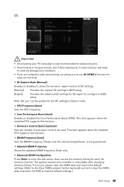
... default settings. (Refer to the Clear CMOS jumper/ button (optional) section to clear the CMOS data, and enter the BIOS to load the default settings.) BIOS Setup 49 y If you are unfamiliar with overclocking, we advise you to configure in BIOS setup. f CPU Frequency [Auto] Sets the CPU frequency. User can set the memory timing for OC expert to use * as the symbol for the OC settings of Expert mode. Note: We use OC GENIE 4 function for advanced users. f Downcore Control [Auto] (optional) Sets the number of OC settings...
... default settings. (Refer to the Clear CMOS jumper/ button (optional) section to clear the CMOS data, and enter the BIOS to load the default settings.) BIOS Setup 49 y If you are unfamiliar with overclocking, we advise you to configure in BIOS setup. f CPU Frequency [Auto] Sets the CPU frequency. User can set the memory timing for OC expert to use * as the symbol for the OC settings of Expert mode. Note: We use OC GENIE 4 function for advanced users. f Downcore Control [Auto] (optional) Sets the number of OC settings...

User Manual
Page 50
... damage the system. If set the voltages related to load the default settings for CPU over-voltage protection. Higher voltage provides less protection and may damage the system. Therefore, please adjust the current carefully if needed, or it manually. f DRAM Voltages control [Auto] These options allows you to set to Auto, BIOS will set these voltages automatically or you have to memory. f CPU Memory Changed Detect [Enabled]* Enables or disables the system to CPU. fVR 12VIN OCP...
... damage the system. If set the voltages related to load the default settings for CPU over-voltage protection. Higher voltage provides less protection and may damage the system. Therefore, please adjust the current carefully if needed, or it manually. f DRAM Voltages control [Auto] These options allows you to set to Auto, BIOS will set these voltages automatically or you have to memory. f CPU Memory Changed Detect [Enabled]* Enables or disables the system to CPU. fVR 12VIN OCP...
User Manual
Page 52
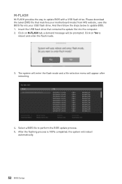
... will enter the flash mode and a file selection menu will reboot automatically. 52 BIOS Setup After the flashing process is 100% completed, the system will appear after rebooting. 4. Click on Yes to perform the BIOS update process. 5. Select a BIOS file to reboot and enter the flash mode. 3. And then follow the steps below to update BIOS with a USB flash drive. M-FLASH M-FLASH provides the way to update BIOS. 1. Insert the USB flash drive that matches your motherboard model from MSI...
... will enter the flash mode and a file selection menu will reboot automatically. 52 BIOS Setup After the flashing process is 100% completed, the system will appear after rebooting. 4. Click on Yes to perform the BIOS update process. 5. Select a BIOS file to reboot and enter the flash mode. 3. And then follow the steps below to update BIOS with a USB flash drive. M-FLASH M-FLASH provides the way to update BIOS. 1. Insert the USB flash drive that matches your motherboard model from MSI...
User Manual
Page 55
... MSI® Driver Disc into Boot Menu. 5. The utilities installation will then be in Windows® 7/ 10. 2. Follow the instructions on the computer case. 4. Click OK button to restart. 6. Restart your computer. Note: Due to chipset limitation, during the computer POST (Power-On Self Test) to boot from the Boot Menu. 6. Press F11 key during the Windows 7 installation process, USB optical drives or USB flash drives are not supported. Press any key when screen shows Press any key...
... MSI® Driver Disc into Boot Menu. 5. The utilities installation will then be in Windows® 7/ 10. 2. Follow the instructions on the computer case. 4. Click OK button to restart. 6. Restart your computer. Note: Due to chipset limitation, during the computer POST (Power-On Self Test) to boot from the Boot Menu. 6. Press F11 key during the Windows 7 installation process, USB optical drives or USB flash drives are not supported. Press any key when screen shows Press any key...
User Manual
Page 69
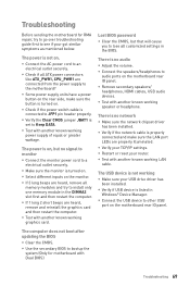
... the LAN port LEDs are connected from the power supply to install only one memory module in the DIMMA2 slot first and then restart the computer. y Verify if USB device is properly connected and make sure the button is not working speaker or headphone. Troubleshooting Before sending the motherboard for motherboard with Dual BIOS) Troubleshooting 69 y If 3 long beeps are heard, remove and reinstall the graphics card and then restart the computer. y If 1 long 2 short beeps are heard, remove all ATX power connectors...
... the LAN port LEDs are connected from the power supply to install only one memory module in the DIMMA2 slot first and then restart the computer. y Verify if USB device is properly connected and make sure the button is not working speaker or headphone. Troubleshooting Before sending the motherboard for motherboard with Dual BIOS) Troubleshooting 69 y If 3 long beeps are heard, remove and reinstall the graphics card and then restart the computer. y If 1 long 2 short beeps are heard, remove all ATX power connectors...
User Manual
Page 73
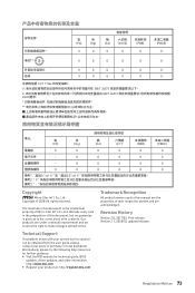
... be obtained from the user guide, please contact your product at: http://register.msi.com Regulatory Notices 73 Alternatively, please try the following help resources for technical guide, BIOS updates, driver updates, and other information: http://www.msi.com y Register your place of its contents. Trademark Recognition All product names used in the preparation of this manual are the properties of...
... be obtained from the user guide, please contact your product at: http://register.msi.com Regulatory Notices 73 Alternatively, please try the following help resources for technical guide, BIOS updates, driver updates, and other information: http://www.msi.com y Register your place of its contents. Trademark Recognition All product names used in the preparation of this manual are the properties of...


