User Guide
Page 3
... work well or you can not step on the equipment should be obtained from overheating. Do not place any of the following help resources for further guidance. ◙ Visit the MSI website for technical guide, BIOS updates, driver updates, and other information: http://www.msi.com/service/download ◙ Contact our technical staff at 110/220V before connecting the equipment to User's Manual...
... work well or you can not step on the equipment should be obtained from overheating. Do not place any of the following help resources for further guidance. ◙ Visit the MSI website for technical guide, BIOS updates, driver updates, and other information: http://www.msi.com/service/download ◙ Contact our technical staff at 110/220V before connecting the equipment to User's Manual...
User Guide
Page 9
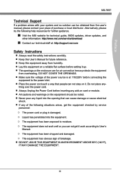
... Electrical and Electronic Equipment) Statement vi Chapter 1 Getting Started 1-1 Packing Contents 1-2 Optional Accessories 1-2 Assembly Precautions 1-3 Mainboard Specifications 1-4 Connectors Quick Guide 1-6 Back Panel Quick Guide 1-8 CPU (Central Processing Unit 1-10 Mounting Screw Holes 1-13 Power Supply 1-14 Memory 1-15 Expansion Slots 1-17 Video/ Graphics Cards 1-18 Internal Connectors 1-19 Jumper 1-25 Chapter 2 BIOS Setup 2-1 Entering Setup 2-2 The Menu Bar 2-4 Main Menu 2-5 Advanced 2-6 Overclocking 2-11 M-Flash 2-16 Security 2-17 Boot 2-19 Save & Exit 2-20 ix
... Electrical and Electronic Equipment) Statement vi Chapter 1 Getting Started 1-1 Packing Contents 1-2 Optional Accessories 1-2 Assembly Precautions 1-3 Mainboard Specifications 1-4 Connectors Quick Guide 1-6 Back Panel Quick Guide 1-8 CPU (Central Processing Unit 1-10 Mounting Screw Holes 1-13 Power Supply 1-14 Memory 1-15 Expansion Slots 1-17 Video/ Graphics Cards 1-18 Internal Connectors 1-19 Jumper 1-25 Chapter 2 BIOS Setup 2-1 Entering Setup 2-2 The Menu Bar 2-4 Main Menu 2-5 Advanced 2-6 Overclocking 2-11 M-Flash 2-16 Security 2-17 Boot 2-19 Save & Exit 2-20 ix
User Guide
Page 14
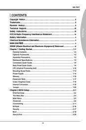
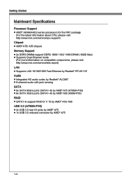
Getting Started Mainboard Specifications Processor Support ■ AMD® A8/A6/A4/E2-series processors for the FM1 package (For the latest information about CPU, please visit http://www.msi.com/service/cpu-support) Chipset ■ AMD® A75/ A55 chipset Memory Support ■ 2x DDR3 DIMMs support DDR3 1600/ 1333/ 1066 DRAM (16GB Max) ■ Supports Dual-Channel mode (For more information on compatible components, please visit http://www.msi.com/service/test-report) LAN ■ Supports LAN 10/100/1000...
Getting Started Mainboard Specifications Processor Support ■ AMD® A8/A6/A4/E2-series processors for the FM1 package (For the latest information about CPU, please visit http://www.msi.com/service/cpu-support) Chipset ■ AMD® A75/ A55 chipset Memory Support ■ 2x DDR3 DIMMs support DDR3 1600/ 1333/ 1066 DRAM (16GB Max) ■ Supports Dual-Channel mode (For more information on compatible components, please visit http://www.msi.com/service/test-report) LAN ■ Supports LAN 10/100/1000...

User Guide
Page 15
... port - 4x USB 2.0 ports - 2x USB 3.0 ports (A75MA-P35) - 1x LAN port - 1x VGA port - 1x DVI-D port - 6x audio ports ■ On-Board - 2x USB 2.0 connectors - 1x USB 3.0 connector (A75MA-P35) - 1x S/PDIF-Out connector - 1x Front Panel Audio connector - 1x TPM Module connector - 1x Parallel connector - 1x Serial connector Slots ■ 1x PCIe 2.0 x16 slots ■ 2x PCIe 2.0 x1 slot ■ 1x PCI slot Form Factor ■ Micro-ATX (24.4 cm X 21.5 cm) Mounting Screw Holes ■ 6x mounting holes Dual-Graphics ■ Supports AMD® Dual Graphics Technology with...
... port - 4x USB 2.0 ports - 2x USB 3.0 ports (A75MA-P35) - 1x LAN port - 1x VGA port - 1x DVI-D port - 6x audio ports ■ On-Board - 2x USB 2.0 connectors - 1x USB 3.0 connector (A75MA-P35) - 1x S/PDIF-Out connector - 1x Front Panel Audio connector - 1x TPM Module connector - 1x Parallel connector - 1x Serial connector Slots ■ 1x PCIe 2.0 x16 slots ■ 2x PCIe 2.0 x1 slot ■ 1x PCI slot Form Factor ■ Micro-ATX (24.4 cm X 21.5 cm) Mounting Screw Holes ■ 6x mounting holes Dual-Graphics ■ Supports AMD® Dual Graphics Technology with...

User Guide
Page 17
Chapter 1 Connectors Reference Guide Port Type FM1 APU Socket ATX 24-pin Power Connector ATX 4-pin Power Connector DDR3 Memory Slots PCIe x16 Expansion Slot PCIe x1 Expansion Slots PCI Expansion Slot SATA 6Gb/s Connectors CPU Fan Connector System Fan Connector Front Panel Connectors Front Panel Audio Connector USB 2.0 Expansion Connectors S/PDIF-Out Expansion Connector TPM Module connector Parallel Port Header Serial Port Connector USB 3.0 Expansion Connector Clear CMOS Jumper USB power Jumper Port Name CPU JPWR1 JPWR2 DIMM1~2 PCI_E1 PCI_E2.3 PCI1 SATA1~6 CPUFAN SYSFAN1~2 JFP1, JFP2 JAUD1 ...
Chapter 1 Connectors Reference Guide Port Type FM1 APU Socket ATX 24-pin Power Connector ATX 4-pin Power Connector DDR3 Memory Slots PCIe x16 Expansion Slot PCIe x1 Expansion Slots PCI Expansion Slot SATA 6Gb/s Connectors CPU Fan Connector System Fan Connector Front Panel Connectors Front Panel Audio Connector USB 2.0 Expansion Connectors S/PDIF-Out Expansion Connector TPM Module connector Parallel Port Header Serial Port Connector USB 3.0 Expansion Connector Clear CMOS Jumper USB power Jumper Port Name CPU JPWR1 JPWR2 DIMM1~2 PCI_E1 PCI_E2.3 PCI1 SATA1~6 CPUFAN SYSFAN1~2 JFP1, JFP2 JAUD1 ...

User Guide
Page 24
Getting Started Power Supply ATX 24-pin Power Connector: JPWR1 This connector allows you to ensure stable operation of the mainboard. 1-14 To connect the ATX 24-pin power supply, align the power supply cable with the connector and firmly press the cable into the connector. If done correctly, the clip on the power cable should be hooked on the mainboard's power connector. 1.+23.+3.33.G4V.3.r+5Vo.5uG6Vn.r7+do.5uG8Vn.rP9do.Wu51nV0R1d.S1+O1B.1+K2211...
Getting Started Power Supply ATX 24-pin Power Connector: JPWR1 This connector allows you to ensure stable operation of the mainboard. 1-14 To connect the ATX 24-pin power supply, align the power supply cable with the connector and firmly press the cable into the connector. If done correctly, the clip on the power cable should be hooked on the mainboard's power connector. 1.+23.+3.33.G4V.3.r+5Vo.5uG6Vn.r7+do.5uG8Vn.rP9do.Wu51nV0R1d.S1+O1B.1+K2211...

User Guide
Page 27
... PCI slot supports additional LAN, SCSI, USB, and other add-on cards that comply with PCI specifications. 32-bit PCI Slot PCI Interrupt Request Routing IRQ, or interrupt request lines, are typically connected to the PCI bus pins as discrete graphics or audio cards. Read the expansion card's documentation to the processor. PCIe (Peripheral Component Interconnect Express) Slot The PCIe slot supports the PCIe interface expansion card. MS-7697 Expansion Slots This mainboard contains numerous ports for any necessary additional hardware or software changes...
... PCI slot supports additional LAN, SCSI, USB, and other add-on cards that comply with PCI specifications. 32-bit PCI Slot PCI Interrupt Request Routing IRQ, or interrupt request lines, are typically connected to the PCI bus pins as discrete graphics or audio cards. Read the expansion card's documentation to the processor. PCIe (Peripheral Component Interconnect Express) Slot The PCIe slot supports the PCIe interface expansion card. MS-7697 Expansion Slots This mainboard contains numerous ports for any necessary additional hardware or software changes...
User Guide
Page 30
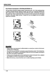
... -board, you must use a specially designed fan with +12V. Getting Started Fan Power Connectors: CPUFAN,SYSFAN1~2 The fan power connectors support system cooling fans with a speed sensor to connect all system fans. The Control Center utility can be installed to automatically control the CPU fan speeds according to the CPU's and system's temperature. • If there are no cables impeding any available system fan connector. If the mainboard has a System Hardware Monitor chipset on the mainboard to take advantage of the CPU fan control.
... -board, you must use a specially designed fan with +12V. Getting Started Fan Power Connectors: CPUFAN,SYSFAN1~2 The fan power connectors support system cooling fans with a speed sensor to connect all system fans. The Control Center utility can be installed to automatically control the CPU fan speeds according to the CPU's and system's temperature. • If there are no cables impeding any available system fan connector. If the mainboard has a System Hardware Monitor chipset on the mainboard to take advantage of the CPU fan control.

User Guide
Page 35
... 2A currents. 1-25 USB power Jumper: JUSB_PW1, JUSB_PW2 The USB ports on the rear IO panel are controled by JUSB_PW1. Afterwards, open the jumper . These jumpers allow you set the jumpers to save system configuration data. The JUSB1 and JUSB2 are controled by USB and PS/2 device" function 1 Disabled (default) 1 Enabled Important If you to enable/ disable the "wakeup from a battery located on the mainboard to clear the CMOS RAM. 1 Keep Data 1 Clear Data Important You can...
... 2A currents. 1-25 USB power Jumper: JUSB_PW1, JUSB_PW2 The USB ports on the rear IO panel are controled by JUSB_PW1. Afterwards, open the jumper . These jumpers allow you set the jumpers to save system configuration data. The JUSB1 and JUSB2 are controled by USB and PS/2 device" function 1 Disabled (default) 1 Enabled Important If you to enable/ disable the "wakeup from a battery located on the mainboard to clear the CMOS RAM. 1 Keep Data 1 Clear Data Important You can...

User Guide
Page 42
... PCI device can hold the bus before another takes over. BIOS Setup Advanced ▶ PCI Subsystem Settings Press to enter the sub-menu. ▶ PCI Latency Timer This item controls how long each PCI device can conduct transactions for ACPI function. ▶ Power LED This item configures how the system uses power LED on the case to indicate the sleep/suspend state. 2-6 When set the item to higher values. ▶ ACPI Settings Press to enter the sub-menu...
... PCI device can hold the bus before another takes over. BIOS Setup Advanced ▶ PCI Subsystem Settings Press to enter the sub-menu. ▶ PCI Latency Timer This item controls how long each PCI device can conduct transactions for ACPI function. ▶ Power LED This item configures how the system uses power LED on the case to indicate the sleep/suspend state. 2-6 When set the item to higher values. ▶ ACPI Settings Press to enter the sub-menu...
User Guide
Page 43
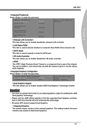
... AMD "dual graphics" technology. • Please visit the AMD official website to find the supported Dual Graphics combinations of APU and discrete GPU for SATA port. ▶ HD Audio Controller This item allows you to enable/ disable the HD audio controller. ▶ HPET The HPET (High Precision Event Timers) is a component that is used to decide whether to invoke the Boot ROM of the onboard LAN. ▶ SATA Mode This item is part of the chipset...
... AMD "dual graphics" technology. • Please visit the AMD official website to find the supported Dual Graphics combinations of APU and discrete GPU for SATA port. ▶ HD Audio Controller This item allows you to enable/ disable the HD audio controller. ▶ HPET The HPET (High Precision Event Timers) is a component that is used to decide whether to invoke the Boot ROM of the onboard LAN. ▶ SATA Mode This item is part of the chipset...
User Guide
Page 44
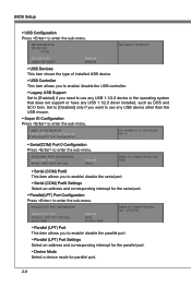
... allows you need to enable/ disable the parallel port. ▶ Parallel (LPT) Port Settings Select an address and corresponding interrupt for the parallel port. ▶ Device Mode Select a device mode for parallel port. 2-8 BIOS Setup ▶ USB Configuration Press to enter the sub-menu. ▶ USB Devices: This item shows the type of installed USB device. ▶ USB Controller This item allows you to enable/ disable the USB controller. ▶ Legacy USB Support Set to [Enabled] if you to use any USB 1.1/2.0 driver installed, such as DOS and...
... allows you need to enable/ disable the parallel port. ▶ Parallel (LPT) Port Settings Select an address and corresponding interrupt for the parallel port. ▶ Device Mode Select a device mode for parallel port. 2-8 BIOS Setup ▶ USB Configuration Press to enter the sub-menu. ▶ USB Devices: This item shows the type of installed USB device. ▶ USB Controller This item allows you to enable/ disable the USB controller. ▶ Legacy USB Support Set to [Enabled] if you to use any USB 1.1/2.0 driver installed, such as DOS and...

User Guide
Page 46
... used to enable or disable the feature of booting up events. BIOS Setup ▶ Wake Up Event Setup Press to enter the sub-menu. ▶ Wake Up Event By Setting to [BIOS] activates the following fields, and use the following fields to set to [Enabled], the feature allows your system to be awakened from the power saving modes through any event on PCI or PCIE device. ▶ Resume From S3 by USB Device...
... used to enable or disable the feature of booting up events. BIOS Setup ▶ Wake Up Event Setup Press to enter the sub-menu. ▶ Wake Up Event By Setting to [BIOS] activates the following fields, and use the following fields to set to [Enabled], the feature allows your system to be awakened from the power saving modes through any event on PCI or PCIE device. ▶ Resume From S3 by USB Device...
User Guide
Page 50
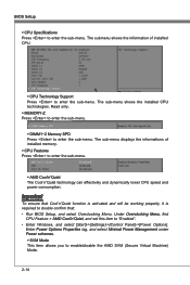
... Overclocking Menu, find CPU Feature > AMD Cool'n'Quiet, and set this item to enable/disable the AMD SVM (Secure Virtual Machine) Mode. 2-14 Enter Power Options Properties tag, and select Minimal Power Management under Power schemes. ▶ SVM Mode This item allows you to "Enabled". • Enter Windows, and select [Start]->[Settings]->[Control Panel]->[Power Options]. Read only. ▶ MEMORY-Z Press to enter the sub-menu. ▶ DIMM1~2 Memory SPD Press to enter the sub-menu. BIOS Setup ▶ CPU Specifications Press to enter the sub-menu...
... Overclocking Menu, find CPU Feature > AMD Cool'n'Quiet, and set this item to enable/disable the AMD SVM (Secure Virtual Machine) Mode. 2-14 Enter Power Options Properties tag, and select Minimal Power Management under Power schemes. ▶ SVM Mode This item allows you to "Enabled". • Enter Windows, and select [Start]->[Settings]->[Control Panel]->[Power Options]. Read only. ▶ MEMORY-Z Press to enter the sub-menu. ▶ DIMM1~2 Memory SPD Press to enter the sub-menu. BIOS Setup ▶ CPU Specifications Press to enter the sub-menu...
User Guide
Page 52
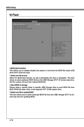
... BIOS Boot function as sets to [Enabled], this item is selectable. And the system will boot from selected BIOS file. ▶ Save BIOS to storage Please setup a specific folder in specific USB/ Storage drive to save BIOS file from the USB/ Storage (FAT/ 32 format only) drive. BIOS Setup M-Flash ▶ BIOS Boot Function This allows you to select particular BIOS file from the USB/ Storage (FAT/ 32 format only) drive for updating BIOS. 2-16 This item allows to select particular BIOS file from BIOS ROM chip...
... BIOS Boot function as sets to [Enabled], this item is selectable. And the system will boot from selected BIOS file. ▶ Save BIOS to storage Please setup a specific folder in specific USB/ Storage drive to save BIOS file from the USB/ Storage (FAT/ 32 format only) drive. BIOS Setup M-Flash ▶ BIOS Boot Function This allows you to select particular BIOS file from the USB/ Storage (FAT/ 32 format only) drive for updating BIOS. 2-16 This item allows to select particular BIOS file from BIOS ROM chip...

User Guide
Page 54
This item allows you to specify the USB drive. ▶ Chassis Intrusion Configuration Press to enter the sub-menu. ▶ Chassis Intrusion This item enables or disables the feature of the field will automatically return to [Reset]. To clear the warning message, set the field to [Enabled] later. 2-18 The setting of recording the chassis intrusion status and issuing a warning message if the chassis is selectable. BIOS Setup ▶ Make U-Key at When the "U-Key" as sets to [Enabled], this item is once opened.
This item allows you to specify the USB drive. ▶ Chassis Intrusion Configuration Press to enter the sub-menu. ▶ Chassis Intrusion This item enables or disables the feature of the field will automatically return to [Reset]. To clear the warning message, set the field to [Enabled] later. 2-18 The setting of recording the chassis intrusion status and issuing a warning message if the chassis is selectable. BIOS Setup ▶ Make U-Key at When the "U-Key" as sets to [Enabled], this item is once opened.

User Guide
Page 56
BIOS Setup Save & Exit ▶ Discard Changes and Exit Use this item to abandon all changes and exit setup. ▶ Save Changes and Reboot Use this item to save changes and reset the system. ▶ Save Changes Use this item to save changes. ▶ Discard Changes Use this item to abandon all changes. ▶ Restore Defaults Use this item to load the optimized default values set by the BIOS vendor. == Boot Override == The installed storage devices will appear on this menu, you can select one of them be a boot device. ▶ Built-in EFI Shell Use this item to enter the EFI Shell. 2-20
BIOS Setup Save & Exit ▶ Discard Changes and Exit Use this item to abandon all changes and exit setup. ▶ Save Changes and Reboot Use this item to save changes and reset the system. ▶ Save Changes Use this item to save changes. ▶ Discard Changes Use this item to abandon all changes. ▶ Restore Defaults Use this item to load the optimized default values set by the BIOS vendor. == Boot Override == The installed storage devices will appear on this menu, you can select one of them be a boot device. ▶ Built-in EFI Shell Use this item to enter the EFI Shell. 2-20

User Guide
Page 58
... following illustrations are based on -screen instructions to install drivers. 7. The setup screen will automati- Click Driver tab. 3. Select Realtek HD Audio Drivers to restart the system. A-2 cally appear. 2. Click Finish to start installing the drivers. 5. Insert the application DVD into the DVD-ROM drive. Click AUDIO button. Click Next to enhance audio applications. Important The HD Audio Configuration software utility is under continuous update to install the Realtek High Definition Audio Driver. 6. Click here 4. Hence, the program...
... following illustrations are based on -screen instructions to install drivers. 7. The setup screen will automati- Click Driver tab. 3. Select Realtek HD Audio Drivers to restart the system. A-2 cally appear. 2. Click Finish to start installing the drivers. 5. Insert the application DVD into the DVD-ROM drive. Click AUDIO button. Click Next to enhance audio applications. Important The HD Audio Configuration software utility is under continuous update to install the Realtek High Definition Audio Driver. 6. Click here 4. Hence, the program...
User Guide
Page 70
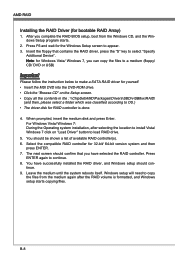
.../ DVD or USB) Important Please follow the instruction below to make a SATA RAID driver for yourself. • Insert the MSI DVD into the DVD-ROM drive. • Click the "Browse CD" on "Load Driver" button to OS.) • The driver disk for Windows Vista/ Windows 7, you complete the RAID BIOS setup, boot from the medium again after selecting the location to install Vista/ Windows 7 click on the Setup screen. • Copy all the contents in the : \\ChipSet\AMD\Packages\Drivers...
.../ DVD or USB) Important Please follow the instruction below to make a SATA RAID driver for yourself. • Insert the MSI DVD into the DVD-ROM drive. • Click the "Browse CD" on "Load Driver" button to OS.) • The driver disk for Windows Vista/ Windows 7, you complete the RAID BIOS setup, boot from the medium again after selecting the location to install Vista/ Windows 7 click on the Setup screen. • Copy all the contents in the : \\ChipSet\AMD\Packages\Drivers...
User Guide
Page 71
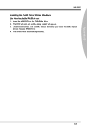
The DVD will auto-run and the setup screen will be automatically installed. The driver will appear. 3. The AMD chipset drivers includes RAID Driver. 4. Under the Driver tab, click on AMD chipset drivers by your need. B-9 Insert the MSI DVD into the DVD-ROM drive. 2. Appendix B MS-7697 Installing the RAID Driver Under Windows (for Non-bootable RAID Array) 1.
The DVD will auto-run and the setup screen will be automatically installed. The driver will appear. 3. The AMD chipset drivers includes RAID Driver. 4. Under the Driver tab, click on AMD chipset drivers by your need. B-9 Insert the MSI DVD into the DVD-ROM drive. 2. Appendix B MS-7697 Installing the RAID Driver Under Windows (for Non-bootable RAID Array) 1.


