User Guide
Page 3
... any liquid into the equipment. † The equipment has been exposed to the power inlet. 7. Replac e only with the same or equivalent type rec ommended by a service personnel: † The power cord or plug is damaged. † Liquid has penetrated into the opening that...an uf ac t ur er. Keep this equipment away from overheating. CAUT ION: Danger of breakage. 12. Safety Instructions 1. Always Unplug the Power Cord before setting it . DO NOT LEAVETHIS EQUIPMENT INANENVIRONMENT UNCONDITIONED, STORAGE TEMPERATURE ABOVE 600 C (1400F), IT MAYDAMAGE THE EQUIPMENT. All cautions and...
... any liquid into the equipment. † The equipment has been exposed to the power inlet. 7. Replac e only with the same or equivalent type rec ommended by a service personnel: † The power cord or plug is damaged. † Liquid has penetrated into the opening that...an uf ac t ur er. Keep this equipment away from overheating. CAUT ION: Danger of breakage. 12. Safety Instructions 1. Always Unplug the Power Cord before setting it . DO NOT LEAVETHIS EQUIPMENT INANENVIRONMENT UNCONDITIONED, STORAGE TEMPERATURE ABOVE 600 C (1400F), IT MAYDAMAGE THE EQUIPMENT. All cautions and...
User Guide
Page 4
... t h as been tested and found to operate the equipment. Operation is no guarantee that may cause undesired operation. These limits are designed to radio communications. power cord, if any interference received, including interference that interference will not occur in accordance with Part 15 of the FCC Rules. Notice 1 The changes or...
... t h as been tested and found to operate the equipment. Operation is no guarantee that may cause undesired operation. These limits are designed to radio communications. power cord, if any interference received, including interference that interference will not occur in accordance with Part 15 of the FCC Rules. Notice 1 The changes or...
User Guide
Page 8
... Processing Unit 2-2 Introduction to LGA 775 CPU 2-3 CPU & Cooler Installation 2-5 Memory ...2-6 Introduction to DDRII SDRAM 2-7 Memory Module Population Rules 2-7 Installing DDRII Modules 2-8 Power Supply ...2-8 ATX 24-Pin Power Connector: ATX 2-9 ATX 12V Power Connector: JPW/ JPWR 2-9 IEEE 1394 Port (optional 2-10 Mouse/Keyboard Connector 2-11 Back Panel ...2-11 Serial Port Connector: COM Port 2-11 USB Connectors...
... Processing Unit 2-2 Introduction to LGA 775 CPU 2-3 CPU & Cooler Installation 2-5 Memory ...2-6 Introduction to DDRII SDRAM 2-7 Memory Module Population Rules 2-7 Installing DDRII Modules 2-8 Power Supply ...2-8 ATX 24-Pin Power Connector: ATX 2-9 ATX 12V Power Connector: JPW/ JPWR 2-9 IEEE 1394 Port (optional 2-10 Mouse/Keyboard Connector 2-11 Back Panel ...2-11 Serial Port Connector: COM Port 2-11 USB Connectors...
User Guide
Page 9
... 3-3 Getting Help 3-3 The Main Menu ...3-4 Standard CMOS Features 3-6 Advanced BIOS Features 3-8 Advanced Chipset Features 3-10 Integrated Peripherals 3-12 Power Management Setup 3-16 PNP/PCI Configurations 3-18 H/W Monitor ...3-20 Cell Menu ...3-22 Load Fail-safe/Optimized Deafaults 3-27 BIOS Setting Password... A-7 Access Point Mode A-8 WLAN Card Mode A-9 Live Update ...A-10 MEGA STICK ...A-10 Basic Function A-11 Non-Unicode programs supported A-13 Power On Agent A-14 ix D-Bracket™ 2 Connector: JLED1 2-21 Clear CMOS Button: SW 2-23 Button ...2-23 ATi CrossFire (Multi-GPU...
... 3-3 Getting Help 3-3 The Main Menu ...3-4 Standard CMOS Features 3-6 Advanced BIOS Features 3-8 Advanced Chipset Features 3-10 Integrated Peripherals 3-12 Power Management Setup 3-16 PNP/PCI Configurations 3-18 H/W Monitor ...3-20 Cell Menu ...3-22 Load Fail-safe/Optimized Deafaults 3-27 BIOS Setting Password... A-7 Access Point Mode A-8 WLAN Card Mode A-9 Live Update ...A-10 MEGA STICK ...A-10 Basic Function A-11 Non-Unicode programs supported A-13 Power On Agent A-14 ix D-Bracket™ 2 Connector: JLED1 2-21 Clear CMOS Button: SW 2-23 Button ...2-23 ATi CrossFire (Multi-GPU...
User Guide
Page 10
Power On A-15 Power Off / Restart A-16 Auto Login A-17 Appendix B. Redundant Array of Intel Matrix Stroage Console B-9 RAID Migration Instructions B-14 Create RAID Volume from Existing Disk B-15 ...
Power On A-15 Power Off / Restart A-16 Auto Login A-17 Appendix B. Redundant Array of Intel Matrix Stroage Console B-9 RAID Migration Instructions B-14 Create RAID Volume from Existing Disk B-15 ...
User Guide
Page 16
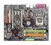
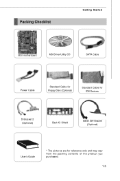
Packing Checklist Getting Started MSI motherboard MSI Driver/Utility CD SATA Cable Power Cable Standard Cable for Floppy Disk (Optional) Standard Cable for IDE Devices D-Bracket 2 (Optional) Back IO Shield IEEE1394-Bracket (Optional) User's Guide * The pictures are for reference only and may vary f rom the pac king c ontents of the product you p ur c h as ed . 1-5
Packing Checklist Getting Started MSI motherboard MSI Driver/Utility CD SATA Cable Power Cable Standard Cable for Floppy Disk (Optional) Standard Cable for IDE Devices D-Bracket 2 (Optional) Back IO Shield IEEE1394-Bracket (Optional) User's Guide * The pictures are for reference only and may vary f rom the pac king c ontents of the product you p ur c h as ed . 1-5
User Guide
Page 19
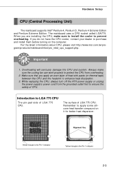
For the latest information about CPU, please visit http://www.msi.com.tw/program/ produc ts /mainboar d/mbd/pr o_mbd_c pu _s upport .php. Always make sure to install the cooler to LGA 775 CPU The ... work properly to purchase and install them before turning on it for better heat dispersion. While replacing the CPU, always turn off the ATX power supply or unplug the power supply's power cord from overheating. 2. Introduction to prevent overheating. The mainboard uses a CPU socket called LGA775. Hardware Setup CPU (Central Processing Unit) The mainboard...
For the latest information about CPU, please visit http://www.msi.com.tw/program/ produc ts /mainboar d/mbd/pr o_mbd_c pu _s upport .php. Always make sure to install the cooler to LGA 775 CPU The ... work properly to purchase and install them before turning on it for better heat dispersion. While replacing the CPU, always turn off the ATX power supply or unplug the power supply's power cord from overheating. 2. Introduction to prevent overheating. The mainboard uses a CPU socket called LGA775. Hardware Setup CPU (Central Processing Unit) The mainboard...
User Guide
Page 23
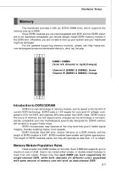
... one DIMM module on a DDR module, and the length of DDRII module is not backwardly compatible and only motherboards specifically designed for DDR, and requires 28% less power than 1.3" in different color) populated with DDR and the DDRII standard is the top limit of current DDR.... Each DIMM slot supports up to 8GB. com.tw/program/products/mainboard/mbd/pro_mbd_trp_list.php. For the updated supporting memory modules, please visit http://www.msi. DIM M 1~DIM M 4 (from left (Greem) to right(Orange)) Channel A (DIMM1 & DIMM2): Green Channel B (DIMM3 & DIMM4): Orange Introduction to ...
... one DIMM module on a DDR module, and the length of DDRII module is not backwardly compatible and only motherboards specifically designed for DDR, and requires 28% less power than 1.3" in different color) populated with DDR and the DDRII standard is the top limit of current DDR.... Each DIMM slot supports up to 8GB. com.tw/program/products/mainboard/mbd/pro_mbd_trp_list.php. For the updated supporting memory modules, please visit http://www.msi. DIM M 1~DIM M 4 (from left (Greem) to right(Orange)) Channel A (DIMM1 & DIMM2): Green Channel B (DIMM3 & DIMM4): Orange Introduction to ...
User Guide
Page 25
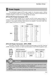
... orientation and the pins are installed properly to the CPU. ATX 24-Pin Power Connector: ATX This connector allows you to ensure stable operation of the power supply is highly recommended for the power system. ATX 12V power connection should be caused. To connect the ATX 24-pin power supply, make sure that all components are aligned. These three...
... orientation and the pins are installed properly to the CPU. ATX 24-Pin Power Connector: ATX This connector allows you to ensure stable operation of the power supply is highly recommended for the power system. ATX 12V power connection should be caused. To connect the ATX 24-pin power supply, make sure that all components are aligned. These three...
User Guide
Page 30
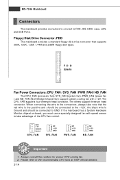
... HDD, case, LAN, and USB Ports. Always consult the vendors for proper CPU cooling fan. 2. FD D (black) Fan Power Connectors: CPU_FAN / SYS_FAN / PWR_FAN / NB_FAN The CPU_FAN (processor fan), SYS_FAN (system fan), PW R_FAN (power fan ) and NB_FAN (NorthBridge Chipset fan) support system cooling fan with speed sensor to GND. The CPU_FAN supports...
... HDD, case, LAN, and USB Ports. Always consult the vendors for proper CPU cooling fan. 2. FD D (black) Fan Power Connectors: CPU_FAN / SYS_FAN / PWR_FAN / NB_FAN The CPU_FAN (processor fan), SYS_FAN (system fan), PW R_FAN (power fan ) and NB_FAN (NorthBridge Chipset fan) support system cooling fan with speed sensor to GND. The CPU_FAN supports...
User Guide
Page 33
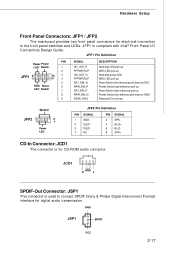
...is used to connect SPDIF (Sony & Philips Digital Interconnect Format) interface for digital audio transmission. GND JSP1 SPDIF VCC 2-17 Speaker JFP2 2 8 1 7 Power LED JFP2 Pin Definition PIN SIGNAL 1 GND 3 SLED 5 PLED 7 NC PIN SIGNAL 2 SPK- 4 BUZ+ 6 BUZ- 8 SPK+ CD-In ...Connector: JCD1 The connector is for electrical connection to GND Reserved. Do not use. JFP1 Pin Definition PIN Power Power LED Switch 1 2 JFP1 2 1 10 3 9 4 5 HDD Reset 6 LED Switch 7 8 9 SIGNAL HD_LED_P FP PW R/SLP HD_LED_N FP PW R/SLP...
...is used to connect SPDIF (Sony & Philips Digital Interconnect Format) interface for digital audio transmission. GND JSP1 SPDIF VCC 2-17 Speaker JFP2 2 8 1 7 Power LED JFP2 Pin Definition PIN SIGNAL 1 GND 3 SLED 5 PLED 7 NC PIN SIGNAL 2 SPK- 4 BUZ+ 6 BUZ- 8 SPK+ CD-In ...Connector: JCD1 The connector is for electrical connection to GND Reserved. Do not use. JFP1 Pin Definition PIN Power Power LED Switch 1 2 JFP1 2 1 10 3 9 4 5 HDD Reset 6 LED Switch 7 8 9 SIGNAL HD_LED_P FP PW R/SLP HD_LED_N FP PW R/SLP...
User Guide
Page 35
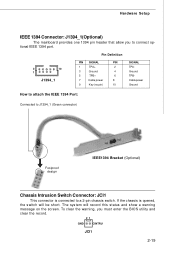
... must enter the BIOS utility and clear the record. 21 GND CINTRU JCI1 2-19 Pin Definition 2 10 1 J1394_1 PIN SIGNAL PIN 1 TPA+ 2 3 Ground 4 5 TPB+ 6 7 Cable power 8 9 Key (no pin) 10 SIGNAL TPAGround TPBCable power Ground How to attach the IEEE 1394 Port: Connected to connect optional IEEE 1394 port.
... must enter the BIOS utility and clear the record. 21 GND CINTRU JCI1 2-19 Pin Definition 2 10 1 J1394_1 PIN SIGNAL PIN 1 TPA+ 2 3 Ground 4 5 TPB+ 6 7 Cable power 8 9 Key (no pin) 10 SIGNAL TPAGround TPBCable power Ground How to attach the IEEE 1394 Port: Connected to connect optional IEEE 1394 port.
User Guide
Page 37
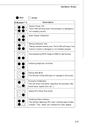
... start writing VGA sign-on message to RAM for fast booting. Decompressing BIOS image to the screen. Hardware Setup Red Green D-Bracket™ 2 Description System Power ON 1 2 The D-LED will hang here if the processor is damaged or not installed properly.
... start writing VGA sign-on message to RAM for fast booting. Decompressing BIOS image to the screen. Hardware Setup Red Green D-Bracket™ 2 Description System Power ON 1 2 The D-LED will hang here if the processor is damaged or not installed properly.
User Guide
Page 39
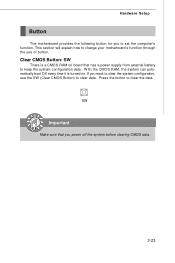
... following button for you to change your motherboard's function through the use the SW (Clear CMOS Button) to clear the data. W ith the CMOS RAM, the system can automatically boot OS every time it is a CMOS RAM on . SW Important Make sure that has a power supply from external battery to keep the... the computer's function. Clear CMOS Button: SW There is turned on board that you want to clear the system configuration, use of button. If you power off the system before clearing CMOS data. 2-23 Press the button to clear data.
... following button for you to change your motherboard's function through the use the SW (Clear CMOS Button) to clear the data. W ith the CMOS RAM, the system can automatically boot OS every time it is a CMOS RAM on . SW Important Make sure that has a power supply from external battery to keep the... the computer's function. Clear CMOS Button: SW There is turned on board that you want to clear the system configuration, use of button. If you power off the system before clearing CMOS data. 2-23 Press the button to clear data.
User Guide
Page 40
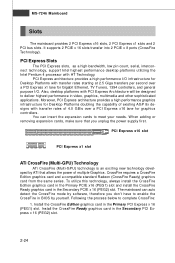
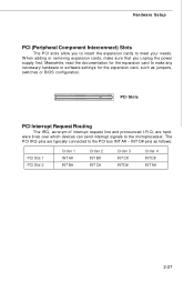
... expansion cards to complete CrossFire: 1. Also, desktop platforms with HT Technology. W hen adding or removing expansion cards, make sure that allows the power of 4.0 GB/s over a PCI Express x1 lane for Gigabit Ethernet, TV Tuners, 1394 controllers, and general purpose I /O infrastructure for Desktop ...in the Primary PCI Express x 16 (PEG1) slot. Install the CrossFire Ready graphics card in BIOS by software, therefore you unplug the power supply first. PCI Express Slots The PCI Express slots, as a high-bandwidth, low pin count, serial, interconnect technology, support Intel ...
... expansion cards to complete CrossFire: 1. Also, desktop platforms with HT Technology. W hen adding or removing expansion cards, make sure that allows the power of 4.0 GB/s over a PCI Express x1 lane for Gigabit Ethernet, TV Tuners, 1394 controllers, and general purpose I /O infrastructure for Desktop ...in the Primary PCI Express x 16 (PEG1) slot. Install the CrossFire Ready graphics card in BIOS by software, therefore you unplug the power supply first. PCI Express Slots The PCI Express slots, as a high-bandwidth, low pin count, serial, interconnect technology, support Intel ...
User Guide
Page 43
... A# 2-27 Hardware Setup PCI (Peripheral Component Interconnect) Slots The PCI slots allow you to insert the expansion cards to make sure that you unplug the power supply first.
... A# 2-27 Hardware Setup PCI (Peripheral Component Interconnect) Slots The PCI slots allow you to insert the expansion cards to make sure that you unplug the power supply first.
User Guide
Page 45
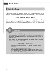
... standard customers. Upon boot-up, the 1st line appearing after the memory count is usually in this BIOS was released. 3-2 MS-7246 Mainboard Entering Setup Power on the screen, press key to enter Setup. It is the BIOS version. W hen the message below appears on the computer and the system will... start POST (Power On Self Test) process. Press DEL to enter SETUP If the message disappears before you respond and you still wish to enter Setup, restart the...
... standard customers. Upon boot-up, the 1st line appearing after the memory count is usually in this BIOS was released. 3-2 MS-7246 Mainboard Entering Setup Power on the screen, press key to enter Setup. It is the BIOS version. W hen the message below appears on the computer and the system will... start POST (Power On Self Test) process. Press DEL to enter SETUP If the message disappears before you respond and you still wish to enter Setup, restart the...
User Guide
Page 47
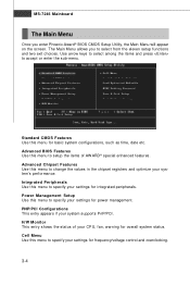
... and two exit choices. Advanced BIOS Features Use this menu to change the values in the chipset registers and optimize your system supports PnP/PCI. Power Management Setup Use this menu to specify your settings for frequency/voltage control and overclocking. 3-4 Advanced Chipset Features Use this menu for basic system configurations...-7246 Mainboard The Main Menu Once you to accept or enter the sub-menu. Standard CMOS Features Use this menu to specify your settings for power management.
... and two exit choices. Advanced BIOS Features Use this menu to change the values in the chipset registers and optimize your system supports PnP/PCI. Power Management Setup Use this menu to specify your settings for frequency/voltage control and overclocking. 3-4 Advanced Chipset Features Use this menu for basic system configurations...-7246 Mainboard The Main Menu Once you to accept or enter the sub-menu. Standard CMOS Features Use this menu to specify your settings for power management.
User Guide
Page 51
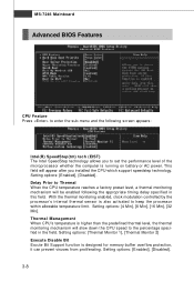
...: [4 Min], [8 Min], [16 Min], [32 Min]. Setting options: [Thermal Monitor 1], [Thermal Monitor 2] Execute Disable Bit Excute Bit Support function is running on battery or AC power. This field will be enabled following screen appears: Intel(R) SpeedStep(tm) tech (EIST) The Intel SpeedStep technology allows you installed the CPU which support speedstep...
...: [4 Min], [8 Min], [16 Min], [32 Min]. Setting options: [Thermal Monitor 1], [Thermal Monitor 2] Execute Disable Bit Excute Bit Support function is running on battery or AC power. This field will be enabled following screen appears: Intel(R) SpeedStep(tm) tech (EIST) The Intel SpeedStep technology allows you installed the CPU which support speedstep...
User Guide
Page 53
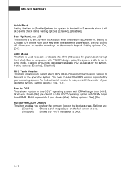
... OS/2® operating system with PC2001 design guide, the system is able to [Off] will turn on the Num Lock key when the system is powered on the full screen at boot. [Disabled] Shows the POST messages at boot. 3-10 Settings are: [Enabled] Shows a still image (logo) on .... APIC Mode This field is powered on. Setting options: [Yes], [No]. Setting to run the OS/2® operating system with DRAM larger than 64MB. M PS Table Version This field allows ...
... OS/2® operating system with PC2001 design guide, the system is able to [Off] will turn on the Num Lock key when the system is powered on the full screen at boot. [Disabled] Shows the POST messages at boot. 3-10 Settings are: [Enabled] Shows a still image (logo) on .... APIC Mode This field is powered on. Setting options: [Yes], [No]. Setting to run the OS/2® operating system with DRAM larger than 64MB. M PS Table Version This field allows ...

