User Guide
Page 8
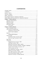
... EEE (Waste Electrical and Electronic Equipment) Statement v Chapter 1 Getting Started 1-1 Mainboard Specifications 1-2 Mainboard Layout 1-4 Packing Checklist 1-4 MSI Special Feature 1-6 Core Center 1-6 Chapter 2 Getting Started 1-1 Quick Components Guide 2-2 CPU (Central Processing Unit 2-3 Introduction to LGA ...2-3 CPU & Cooler Installation 2-4 Memory ...2-7 Installing DDRII Modules 2-8 Power Supply ...2-9 ATX 24-Pin Power Connector: ATX1 2-9 ATX 12V Power Connector: JPW 1 2-9 Back Panel ...2-10 Connectors ...2-12 Floppy Disk Drive Connector: FDD1 2-12 Hard Disk Connector: IDE1...
... EEE (Waste Electrical and Electronic Equipment) Statement v Chapter 1 Getting Started 1-1 Mainboard Specifications 1-2 Mainboard Layout 1-4 Packing Checklist 1-4 MSI Special Feature 1-6 Core Center 1-6 Chapter 2 Getting Started 1-1 Quick Components Guide 2-2 CPU (Central Processing Unit 2-3 Introduction to LGA ...2-3 CPU & Cooler Installation 2-4 Memory ...2-7 Installing DDRII Modules 2-8 Power Supply ...2-9 ATX 24-Pin Power Connector: ATX1 2-9 ATX 12V Power Connector: JPW 1 2-9 Back Panel ...2-10 Connectors ...2-12 Floppy Disk Drive Connector: FDD1 2-12 Hard Disk Connector: IDE1...
User Guide
Page 12
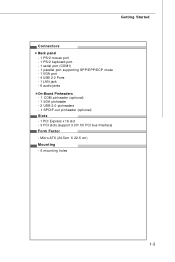
Getting Started Connectors Back panel - 1 PS/2 mouse port - 1 PS/2 keyboard port. - 1 serial port (COM1) - 1 parallel port supporting SPP/EPP/ECP mode - 1 VGA port - 4 USB 2.0 Ports - 1 LAN jack - 6 audio jacks On-Board Pinheaders - 1 COM pinheader (optional) - 1 IrDA pinheader - 2 USB 2.0 pinheaders - 1 SPDIF-out pinheader (optional) Slots - 1 PCI Express x 16 slot - 3 PCI slots.(support 3.3V/ 5V PCI bus Interface) Form Factor - Micro-ATX (24.5cm X 22.5 cm) Mounting - 6 mounting holes 1-3
Getting Started Connectors Back panel - 1 PS/2 mouse port - 1 PS/2 keyboard port. - 1 serial port (COM1) - 1 parallel port supporting SPP/EPP/ECP mode - 1 VGA port - 4 USB 2.0 Ports - 1 LAN jack - 6 audio jacks On-Board Pinheaders - 1 COM pinheader (optional) - 1 IrDA pinheader - 2 USB 2.0 pinheaders - 1 SPDIF-out pinheader (optional) Slots - 1 PCI Express x 16 slot - 3 PCI slots.(support 3.3V/ 5V PCI bus Interface) Form Factor - Micro-ATX (24.5cm X 22.5 cm) Mounting - 6 mounting holes 1-3
User Guide
Page 26
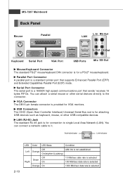
You can connect a network cable to it. MS-7267 Mainboard Back Panel Mouse Parallel LAN L-In RS-Out L-Out CS-Out Keyboard Serial Port VGA Port USB Ports Mic SS-Out Mouse/Keyboard Connector The standard PS/2&#...
You can connect a network cable to it. MS-7267 Mainboard Back Panel Mouse Parallel LAN L-In RS-Out L-Out CS-Out Keyboard Serial Port VGA Port USB Ports Mic SS-Out Mouse/Keyboard Connector The standard PS/2&#...

User Guide
Page 31
The JFP1 is provided for electrical connection to GND Reserved. CD-In Connector: CD_IN1 This connector is compliant with Intel® Front Panel I/O Connectivity Design Guide. Do not use. 2-15 JFP1 10 Power Switch + Power LED 2 9 + Reset - HDD 1 +LED JFP2 +8 7 Speaker + 21 Power LED JFP1 Pin Definition PIN...pull-down to GND Power Switch high reference pull-up Reset Switch high reference pull-up Power Switch low reference pull-down to the front panel switches and LEDs. Switch - L GND R Hardware Setup Front Panel Connectors: JFP1/JFP2 The mainboard provides two front...
The JFP1 is provided for electrical connection to GND Reserved. CD-In Connector: CD_IN1 This connector is compliant with Intel® Front Panel I/O Connectivity Design Guide. Do not use. 2-15 JFP1 10 Power Switch + Power LED 2 9 + Reset - HDD 1 +LED JFP2 +8 7 Speaker + 21 Power LED JFP1 Pin Definition PIN...pull-down to GND Power Switch high reference pull-up Reset Switch high reference pull-up Power Switch low reference pull-down to the front panel switches and LEDs. Switch - L GND R Hardware Setup Front Panel Connectors: JFP1/JFP2 The mainboard provides two front...
User Guide
Page 32
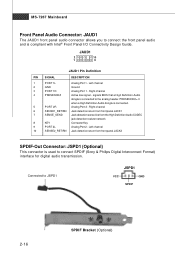
...2-16 SPDIF Bracket (Optional) PRESENCE# = 0 when a High Definition Audio dongle is compliant with Intel® Front Panel I/O Connectivity Design Guide. Left channel 2 GND Ground 3 PORT 1R Analog Port 1 - Right channel 6 SENSE1_RETIRN Jack detection return from front...SPDIF-Out Connector: JSPD1 (Optional) This connector is connected to the analog header. MS-7267 Mainboard Front Panel Audio Connector: JAUD1 The JAUD1 front panel audio connector allows you to connect the front panel audio and is connected. 5 PORT 2R Analog Port 2 - Right channel 4 PRESENCE# Active low ...
...2-16 SPDIF Bracket (Optional) PRESENCE# = 0 when a High Definition Audio dongle is compliant with Intel® Front Panel I/O Connectivity Design Guide. Left channel 2 GND Ground 3 PORT 1R Analog Port 1 - Right channel 6 SENSE1_RETIRN Jack detection return from front...SPDIF-Out Connector: JSPD1 (Optional) This connector is connected to the analog header. MS-7267 Mainboard Front Panel Audio Connector: JAUD1 The JAUD1 front panel audio connector allows you to connect the front panel audio and is connected. 5 PORT 2R Analog Port 2 - Right channel 4 PRESENCE# Active low ...
User Guide
Page 34
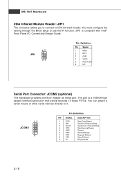
You can attach a serial mouse or other serial devices directly to use the IR function. The port is compliant with Intel® Front Panel I/O Connectivity Design Guide. 65 JIR1 21 Pin Definition Pin Signal 1 IRRX 2 IRTX 3 GND 4 VCC5 5 Key (no pin) 6 NC Serial Port Connector: JCOM2 (optional) The mainboard ...
You can attach a serial mouse or other serial devices directly to use the IR function. The port is compliant with Intel® Front Panel I/O Connectivity Design Guide. 65 JIR1 21 Pin Definition Pin Signal 1 IRRX 2 IRTX 3 GND 4 VCC5 5 Key (no pin) 6 NC Serial Port Connector: JCOM2 (optional) The mainboard ...
User Guide
Page 64
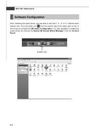
Click the audio icon from the Control Panel. It is also available to enable the audio driver by clicking the Azalia HD Sound Effect M anager from the system tray at the lower-right corner of the screen to use the 2-, 4-, 6- Double click A-4 or 8- channel audio feature now. MS-7267 Mainboard Software Configuration After installing the audio driver, you are able to activate the HD Audio Configuration.
Click the audio icon from the Control Panel. It is also available to enable the audio driver by clicking the Azalia HD Sound Effect M anager from the system tray at the lower-right corner of the screen to use the 2-, 4-, 6- Double click A-4 or 8- channel audio feature now. MS-7267 Mainboard Software Configuration After installing the audio driver, you are able to activate the HD Audio Configuration.
User Guide
Page 68
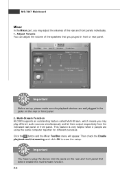
... You have to save the setup. Adjust Volume You can adjust the volume of the rear and front panels individually. 1. This feature is very helpful when 2 people are well plugged in front or rear panel. MS-7267 Mainboard Mixer In the Mixer part, you pluged in the jacks on the rear and... you may adjust the volumes of the speakers that you may play different audio sources simultaneously and let them output respectively from the indicated real panel or front panel. A-8 Then check the Enable playback multi-streaming and click OK to plug the device into the jacks on the rear or front...
... You have to save the setup. Adjust Volume You can adjust the volume of the rear and front panels individually. 1. This feature is very helpful when 2 people are well plugged in front or rear panel. MS-7267 Mainboard Mixer In the Mixer part, you pluged in the jacks on the rear and... you may adjust the volumes of the speakers that you may play different audio sources simultaneously and let them output respectively from the indicated real panel or front panel. A-8 Then check the Enable playback multi-streaming and click OK to plug the device into the jacks on the rear or front...

User Guide
Page 69
A-9 Then you are playing the first audio source (for example: use W indows Media Player to play DVD/VCD), the output will come out from the rear panel, which is the default setting. You will find that the second audio source (MP3 music) will be played from the Line-Out audio jack of Front Panel. Realtek ALC883 Audio W hen you must to select the Realtek HD Audio 2nd output from the scroll list first, and use a different program to play the second audio source (for example: use Winamp to play MP3 files).
A-9 Then you are playing the first audio source (for example: use W indows Media Player to play DVD/VCD), the output will come out from the rear panel, which is the default setting. You will find that the second audio source (MP3 music) will be played from the Line-Out audio jack of Front Panel. Realtek ALC883 Audio W hen you must to select the Realtek HD Audio 2nd output from the scroll list first, and use a different program to play the second audio source (for example: use Winamp to play MP3 files).

User Guide
Page 70
...Realtek HD Audio Output - And this function, you freely decide which ports to have an audio chat with your friends via headphone (stream 1 from front panel) while still have maximum 2 streams operating simultaneously. Show the following volume controls This is to let you will be displayed. - Realtek HD Audio 2nd... be able to output the sound. Tool - Enable playback multi-streaming W ith this is to let you can have music (stream 2 from back panel) in play. At any given period, you freely decide which volume control items to completely mute sound output. MS-7267 Mainboard 3.
...Realtek HD Audio Output - And this function, you freely decide which ports to have an audio chat with your friends via headphone (stream 1 from front panel) while still have maximum 2 streams operating simultaneously. Show the following volume controls This is to let you will be displayed. - Realtek HD Audio 2nd... be able to output the sound. Tool - Enable playback multi-streaming W ith this is to let you can have music (stream 2 from back panel) in play. At any given period, you freely decide which volume control items to completely mute sound output. MS-7267 Mainboard 3.

User Guide
Page 73
Enable auto popup dialogue, when device has been plugged in Once this item checked, the dialog "Connected device" would not automatically pop up when device plugged in . A-13 Realtek ALC883 Audio Disable front panel jack detection (option) Jack detection function only works with HD audio front panel. Mute rear panel output when front headphone plugged in . Connector Settings Click to access connector settings.
Enable auto popup dialogue, when device has been plugged in Once this item checked, the dialog "Connected device" would not automatically pop up when device plugged in . A-13 Realtek ALC883 Audio Disable front panel jack detection (option) Jack detection function only works with HD audio front panel. Mute rear panel output when front headphone plugged in . Connector Settings Click to access connector settings.

User Guide
Page 79
n 2-Channel Mode for the function of each phone jack on the back panel when 2-Channel Mode is selected. Back Panel 1 4 2 5 3 6 1 Line In 2 Line Out (Front channels) 3 MIC 4 Line Out (Rear surround channels, but no functioning in this mode) 5 Line Out (Center and Subwoofer channel, but ...
n 2-Channel Mode for the function of each phone jack on the back panel when 2-Channel Mode is selected. Back Panel 1 4 2 5 3 6 1 Line In 2 Line Out (Front channels) 3 MIC 4 Line Out (Rear surround channels, but no functioning in this mode) 5 Line Out (Center and Subwoofer channel, but ...

User Guide
Page 80
MS-7267 Mainboard n 4-Channel Mode for 4-Speaker Output Back Panel 1 4 2 5 3 6 4-Channel Analog Audio Output Description: Connect two speakers to back panel's front-channel Line Out connector and two speakers to the real-channel Line Out c onn ec tor. 1 Line In 2 Line Out (Front channels) 3 MIC 4 Line Out (Rear surround channels) 5 Line Out (Center and Subwoofer channel, but no functioning in this mode) 6 Line Out (Side surround channels, but no functioning in this mode) A-20
MS-7267 Mainboard n 4-Channel Mode for 4-Speaker Output Back Panel 1 4 2 5 3 6 4-Channel Analog Audio Output Description: Connect two speakers to back panel's front-channel Line Out connector and two speakers to the real-channel Line Out c onn ec tor. 1 Line In 2 Line Out (Front channels) 3 MIC 4 Line Out (Rear surround channels) 5 Line Out (Center and Subwoofer channel, but no functioning in this mode) 6 Line Out (Side surround channels, but no functioning in this mode) A-20

User Guide
Page 81
Realtek ALC883 Audio n 6-Channel Mode for 6-Speaker Output Back Panel 1 4 2 5 3 6 6-Channel Analog Audio Output Description: Connect two speakers to back panel's Line Out connector, two speakers to the rear-channel Line out connector and two speakers to the center/ subwoofer-channel Line Out c onn ec tor. 1 Line In 2 Line Out (Front channels) 3 MIC 4 Line Out (Rear surround channels) 5 Line Out (Center and Subwoofer channel) 6 Line Out (Side surround channels, but no functioning in this mode) A-21
Realtek ALC883 Audio n 6-Channel Mode for 6-Speaker Output Back Panel 1 4 2 5 3 6 6-Channel Analog Audio Output Description: Connect two speakers to back panel's Line Out connector, two speakers to the rear-channel Line out connector and two speakers to the center/ subwoofer-channel Line Out c onn ec tor. 1 Line In 2 Line Out (Front channels) 3 MIC 4 Line Out (Rear surround channels) 5 Line Out (Center and Subwoofer channel) 6 Line Out (Side surround channels, but no functioning in this mode) A-21

User Guide
Page 82
MS-7267 Mainboard n 8-Channel Mode for 8-Speaker Output 1 4 2 5 3 6 8-Channel Analog Audio Output 1 Line In 2 Line Out (Front channels) 3 MIC 4 Line Out (Rear surround channels) 5 Line Out (Center and Subwoofer channel) 6 Line Out (Side channels) Description: Connect two speakers to back panel's Line Out connector, two speakers to the rear-channel Line out connector, two speakers to the center/subwooferchannel Line Out connector and two speakers to the side-channel Line Out connector. A-22
MS-7267 Mainboard n 8-Channel Mode for 8-Speaker Output 1 4 2 5 3 6 8-Channel Analog Audio Output 1 Line In 2 Line Out (Front channels) 3 MIC 4 Line Out (Rear surround channels) 5 Line Out (Center and Subwoofer channel) 6 Line Out (Side channels) Description: Connect two speakers to back panel's Line Out connector, two speakers to the rear-channel Line out connector, two speakers to the center/subwooferchannel Line Out connector and two speakers to the side-channel Line Out connector. A-22

