User Guide
Page 8
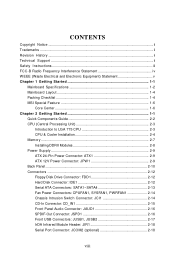
...Waste Electrical and Electronic Equipment) Statement v Chapter 1 Getting Started 1-1 Mainboard Specifications 1-2 Mainboard Layout 1-4 Packing Checklist 1-4 MSI Special Feature 1-6 Core Center 1-6 Chapter 2 Getting Started 1-1 Quick Components... Guide 2-2 CPU (Central Processing Unit 2-3 Introduction to LGA 775 CPU 2-3 CPU & Cooler Installation 2-4 Memory ...2-7 Installing DDRII Modules 2-8 Power Supply ...2-9 ATX 24-Pin Power Connector: ATX1 2-9 ATX...
...Waste Electrical and Electronic Equipment) Statement v Chapter 1 Getting Started 1-1 Mainboard Specifications 1-2 Mainboard Layout 1-4 Packing Checklist 1-4 MSI Special Feature 1-6 Core Center 1-6 Chapter 2 Getting Started 1-1 Quick Components... Guide 2-2 CPU (Central Processing Unit 2-3 Introduction to LGA 775 CPU 2-3 CPU & Cooler Installation 2-4 Memory ...2-7 Installing DDRII Modules 2-8 Power Supply ...2-9 ATX 24-Pin Power Connector: ATX1 2-9 ATX...
User Guide
Page 10
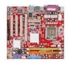
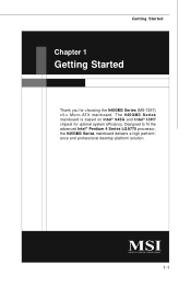
Designed to fit the advanced Intel® Pentium 4 Series LGA775 processor, the 945GM3 Series mainboard delivers a high performance and professional desktop platform solution. 1-1 Getting Started Chapter 1 Getting Started Thank you for optimal system efficiency. The 945G M 3 Series mainboard is based on Intel® 945G and Intel® ICH7 chipset for choosing the 945GM3 Series (MS-7267) v3.x Mic ro-AT X mainboard.
Designed to fit the advanced Intel® Pentium 4 Series LGA775 processor, the 945GM3 Series mainboard delivers a high performance and professional desktop platform solution. 1-1 Getting Started Chapter 1 Getting Started Thank you for optimal system efficiency. The 945G M 3 Series mainboard is based on Intel® 945G and Intel® ICH7 chipset for choosing the 945GM3 Series (MS-7267) v3.x Mic ro-AT X mainboard.
User Guide
Page 11
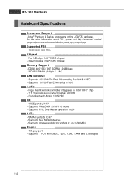
... 8100C Audio - Supports storage and data transfers at up to 300MB/s Floppy - 1 floppy port - Supports four SATA II devices - MS-7267 Mainboard Mainboard Specifications Processor Support - Intel® Pentium 4 Series processors in Intel® ICH7 chip - 7.1 channels audio codec Realtek ALC883 - Compliant with 360K... by ICH7 - SATA II ports by Realtek 8110SC - For the latest information about CPU, please visit http://www.msi.com.tw/ program/products/mainboard/mbd/pro_mbd_cpu_support.php Supported FSB - 1066/ 800/ 533 MHz Chipset - Supports 10/100/1000 Fast Ethermet by ICH7...
... 8100C Audio - Supports storage and data transfers at up to 300MB/s Floppy - 1 floppy port - Supports four SATA II devices - MS-7267 Mainboard Mainboard Specifications Processor Support - Intel® Pentium 4 Series processors in Intel® ICH7 chip - 7.1 channels audio codec Realtek ALC883 - Compliant with 360K... by ICH7 - SATA II ports by Realtek 8110SC - For the latest information about CPU, please visit http://www.msi.com.tw/ program/products/mainboard/mbd/pro_mbd_cpu_support.php Supported FSB - 1066/ 800/ 533 MHz Chipset - Supports 10/100/1000 Fast Ethermet by ICH7...
User Guide
Page 13
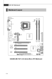
Ou t M:CS-Out B:S S-Out Winbond I n M:Li ne-Out B:Mic T:R S- MS-7267 Mainboard Mainboard Layout Top : mouse Bottom: keyboard Top : Parallel Port Bottom: COM A VGA Port CP UFA N1 DIMM1 DIMM2 USB ports JCI1 T: LAN jack B: USB ports JPW1 JIR1 T:L i ne -I /O ATX1 JCOM2 ( op t io n al ) LAN Chip (optional) PCI3 PCIE_X16 PCI2 ALC883 PCI1 JAUD1 CD_IN1 JSPD1 ( Op tio na l) Intel 945G FDD1 SYS FA N1 PWRFAN1 BATT + BIOS JB AT1 JFP2 JFP1 JUSB2 JUSB1 IDE 1 945GM3 (MS-7267 v3.X) Series Micro-ATX Mainboard S ATA 4 SATA1 SATA2 SATA3 1-4
Ou t M:CS-Out B:S S-Out Winbond I n M:Li ne-Out B:Mic T:R S- MS-7267 Mainboard Mainboard Layout Top : mouse Bottom: keyboard Top : Parallel Port Bottom: COM A VGA Port CP UFA N1 DIMM1 DIMM2 USB ports JCI1 T: LAN jack B: USB ports JPW1 JIR1 T:L i ne -I /O ATX1 JCOM2 ( op t io n al ) LAN Chip (optional) PCI3 PCIE_X16 PCI2 ALC883 PCI1 JAUD1 CD_IN1 JSPD1 ( Op tio na l) Intel 945G FDD1 SYS FA N1 PWRFAN1 BATT + BIOS JB AT1 JFP2 JFP1 JUSB2 JUSB1 IDE 1 945GM3 (MS-7267 v3.X) Series Micro-ATX Mainboard S ATA 4 SATA1 SATA2 SATA3 1-4
User Guide
Page 15
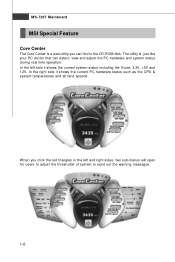
... triangles in the CD-ROM disk. In the right side it shows the current system status including the Vcore, 3.3V, +5V and 12V. MS-7267 Mainboard MSI Special Feature Core Center The Core Center is just like your PC doctor that can find in the left side it shows the current PC...
... triangles in the CD-ROM disk. In the right side it shows the current system status including the Vcore, 3.3V, +5V and 12V. MS-7267 Mainboard MSI Special Feature Core Center The Core Center is just like your PC doctor that can find in the left side it shows the current PC...
User Guide
Page 19
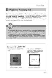
For the latest information about CPU, please visit http://www.msi.com.tw/program/ products/mainboard/mbd/pro_mbd_cpu_support.php Important 1. Introduction to LGA 775 CPU The pin-pad side of LGA 775 CPU. Overheating will seriously damage the CPU and ... 1 indicator Yellow triangle is the Pin 1 indicator 2-3 While replacing the CPU, always turn off the ATX power supply or unplug the power supply's power cord from overheating. 2. Hardware Setup CPU (Central Processing Unit) The mainboard supports Intel® Pentium 4 series processors. If you apply an even layer of CPU. Always make...
For the latest information about CPU, please visit http://www.msi.com.tw/program/ products/mainboard/mbd/pro_mbd_cpu_support.php Important 1. Introduction to LGA 775 CPU The pin-pad side of LGA 775 CPU. Overheating will seriously damage the CPU and ... 1 indicator Yellow triangle is the Pin 1 indicator 2-3 While replacing the CPU, always turn off the ATX power supply or unplug the power supply's power cord from overheating. 2. Hardware Setup CPU (Central Processing Unit) The mainboard supports Intel® Pentium 4 series processors. If you apply an even layer of CPU. Always make...
User Guide
Page 20
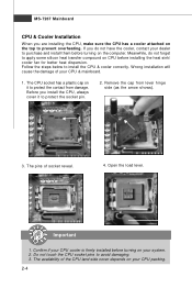
Remove the cap from damage. The pins of the CPU land side cover depends on your CPU & mainboard. 1. Meanwhile, do not have the cooler, contact your system. 2. Follow the steps below to protect the socket pin. 2. W rong installation will cause the damage of ... avoid damaging. 3. Important 1. If you do not forget to apply some silicon heat transfer compound on it to install the CPU & cooler correctly. MS-7267 Mainboard CPU & Cooler Installation W hen you are installing the CPU, make sure the CPU has a cooler attached on the computer.
Remove the cap from damage. The pins of the CPU land side cover depends on your CPU & mainboard. 1. Meanwhile, do not have the cooler, contact your system. 2. Follow the steps below to protect the socket pin. 2. W rong installation will cause the damage of ... avoid damaging. 3. Important 1. If you do not forget to apply some silicon heat transfer compound on it to install the CPU & cooler correctly. MS-7267 Mainboard CPU & Cooler Installation W hen you are installing the CPU, make sure the CPU has a cooler attached on the computer.
User Guide
Page 22
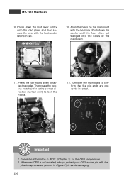
...Then rotate the locking switch (refer to lock the h ook s . 12. Turn over the mainboard to fasten the cooler. MS-7267 Mainboard 9. Align the holes on it) to the correct direction marked on the mainboard with the hook under retention tab. 10. locking switch Important 1. Push down to confirm that the... clip-ends are correctly inserted. Press the four hooks down the cooler until its four clips get wedged into the holes of the mainboard. 11. Whenever CPU is not installed, always protect your CPU socket pin with the plastic cap covered (shown in BIOS (Chapter 3) ...
...Then rotate the locking switch (refer to lock the h ook s . 12. Turn over the mainboard to fasten the cooler. MS-7267 Mainboard 9. Align the holes on it) to the correct direction marked on the mainboard with the hook under retention tab. 10. locking switch Important 1. Push down to confirm that the... clip-ends are correctly inserted. Press the four hooks down the cooler until its four clips get wedged into the holes of the mainboard. 11. Whenever CPU is not installed, always protect your CPU socket pin with the plastic cap covered (shown in BIOS (Chapter 3) ...
User Guide
Page 23
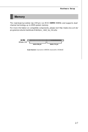
DDRII 240-pin, 1.8V 64x2=128 pin 56x2=112 pin Dual-Channel: Channel A in ORANGE 2-7 For more information on compatible components, please visit http://www.msi.com.tw/ p ro gr a m/ pr od u c t s / m ainb o ar d/ mb d /p ro _ mb d_ t rp _lis t .p hp . Channel B in GREEN; Hardware Setup Memory The mainboard provides two 240-pin non-ECC DDRII DIMMs and supports dualchannel technology up to 2GB system memory.
DDRII 240-pin, 1.8V 64x2=128 pin 56x2=112 pin Dual-Channel: Channel A in ORANGE 2-7 For more information on compatible components, please visit http://www.msi.com.tw/ p ro gr a m/ pr od u c t s / m ainb o ar d/ mb d /p ro _ mb d_ t rp _lis t .p hp . Channel B in GREEN; Hardware Setup Memory The mainboard provides two 240-pin non-ECC DDRII DIMMs and supports dualchannel technology up to 2GB system memory.
User Guide
Page 24
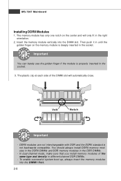
... backwards compatible. Volt Notch Important - You should always install DDRII memory modules in the DDRII DIMMs and DDR memory modules in the socket. 3. MS-7267 Mainboard Installing DDRII Modules 1. The memory module has only one notch on the memory module is deeply inserted in until the golden finger on the center...
... backwards compatible. Volt Notch Important - You should always install DDRII memory modules in the DDRII DIMMs and DDR memory modules in the socket. 3. MS-7267 Mainboard Installing DDRII Modules 1. The memory module has only one notch on the memory module is deeply inserted in until the golden finger on the center...
User Guide
Page 25
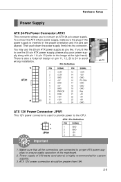
... supply as you like to the image at the right hand). To connect the ATX 24-pin power supply, make sure the plug of the mainboard. 2. Hardware Setup Power Supply ATX 24-Pin Power Connector: ATX1 This connector allows you to ensure stable operation of the power supply is highly recommended for system...
... supply as you like to the image at the right hand). To connect the ATX 24-pin power supply, make sure the plug of the mainboard. 2. Hardware Setup Power Supply ATX 24-Pin Power Connector: ATX1 This connector allows you to ensure stable operation of the power supply is highly recommended for system...
User Guide
Page 26
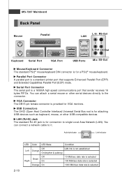
.../ receives 16 bytes FIFOs. You can connect a network cable to the connector. Parallel Port Connector A parallel port is for a PS/2® mouse/keyboard. MS-7267 Mainboard Back Panel Mouse Parallel LAN L-In RS-Out L-Out CS-Out Keyboard Serial Port VGA Port USB Ports Mic SS-Out Mouse/Keyboard Connector The...
.../ receives 16 bytes FIFOs. You can connect a network cable to the connector. Parallel Port Connector A parallel port is for a PS/2® mouse/keyboard. MS-7267 Mainboard Back Panel Mouse Parallel LAN L-In RS-Out L-Out CS-Out Keyboard Serial Port VGA Port USB Ports Mic SS-Out Mouse/Keyboard Connector The...
User Guide
Page 28
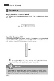
...ROM drives and other IDE devices. Refer to Slave mode by hard disk vendors for jumper setting instructions. 2-12 FDD1 Hard Disk Connector: IDE1 The mainboard provides a one-channel Ultra ATA 100 bus Master IDE controller that supports PIO mode 0~4, Bus Master, and Ultra DMA 66/100 function. Important If... disks on cable, you must configure the second hard drive to the hard disk documentation supplied by setting the jumper accordingly. MS-7267 Mainboard Connectors Floppy Disk Drive Connector: FDD1 This standard FDD connector supports 360K, 720K, 1.2M, 1.44M and 2.88M floppy disk types.
...ROM drives and other IDE devices. Refer to Slave mode by hard disk vendors for jumper setting instructions. 2-12 FDD1 Hard Disk Connector: IDE1 The mainboard provides a one-channel Ultra ATA 100 bus Master IDE controller that supports PIO mode 0~4, Bus Master, and Ultra DMA 66/100 function. Important If... disks on cable, you must configure the second hard drive to the hard disk documentation supplied by setting the jumper accordingly. MS-7267 Mainboard Connectors Floppy Disk Drive Connector: FDD1 This standard FDD connector supports 360K, 720K, 1.2M, 1.44M and 2.88M floppy disk types.
User Guide
Page 30
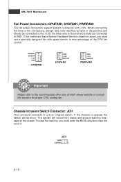
... for proper CPU cooling fan. To clear the warning, you must enter the BIOS utility and clear the record. JCI1 GND CINTRU 1 2-14 MS-7267 Mainboard Fan Power Connectors: CPUFAN1, SYSFAN1, PWRFAN1 The fan power connectors support system cooling fan with speed sensor to take note that the red wire is... ol . CONTROL SE NS OR +1 2V GND CPUFAN1 GND +12V SENSOR SYSFAN1 GND +12V SENSOR PWRFAN1 Important Please refer to a 2-pin chassis switch. If the mainboard has a System Hardware Monitor chipset on the screen.
... for proper CPU cooling fan. To clear the warning, you must enter the BIOS utility and clear the record. JCI1 GND CINTRU 1 2-14 MS-7267 Mainboard Fan Power Connectors: CPUFAN1, SYSFAN1, PWRFAN1 The fan power connectors support system cooling fan with speed sensor to take note that the red wire is... ol . CONTROL SE NS OR +1 2V GND CPUFAN1 GND +12V SENSOR SYSFAN1 GND +12V SENSOR PWRFAN1 Important Please refer to a 2-pin chassis switch. If the mainboard has a System Hardware Monitor chipset on the screen.

User Guide
Page 31
L GND R Hardware Setup Front Panel Connectors: JFP1/JFP2 The mainboard provides two front panel connectors for CD-ROM audio. The JFP1 is provided for electrical connection to GND Reserved. Switch - JFP1 10 Power Switch + Power ...
L GND R Hardware Setup Front Panel Connectors: JFP1/JFP2 The mainboard provides two front panel connectors for CD-ROM audio. The JFP1 is provided for electrical connection to GND Reserved. Switch - JFP1 10 Power Switch + Power ...
User Guide
Page 32
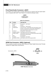
MS-7267 Mainboard Front Panel Audio Connector: JAUD1 The JAUD1 front panel audio connector allows you to connect the front panel audio and is connected to the analog ...
MS-7267 Mainboard Front Panel Audio Connector: JAUD1 The JAUD1 front panel audio connector allows you to connect the front panel audio and is connected to the analog ...

User Guide
Page 33
... Connected to JUSB1/2 USB 2.0 Bracket (Optional) Important Note that are compliant with Intel® I/O Connectivity Design Guide. Hardware Setup Front USB Connectors: JUSB1, JUSB2 The mainboard provides two USB 2.0 pinheaders (optional USB 2.0 bracket available) that the pins of 480Mbps, which is 40 times faster than USB 1.1, and is ideal for connecting...
... Connected to JUSB1/2 USB 2.0 Bracket (Optional) Important Note that are compliant with Intel® I/O Connectivity Design Guide. Hardware Setup Front USB Connectors: JUSB1, JUSB2 The mainboard provides two USB 2.0 pinheaders (optional USB 2.0 bracket available) that the pins of 480Mbps, which is 40 times faster than USB 1.1, and is ideal for connecting...
User Guide
Page 34
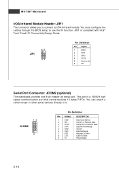
MS-7267 Mainboard IrDA Infrared Module Header: JIR1 The connector allows you to connect to it. 12 JCOM2 9 Pin Definition PIN SIGNAL 1 DCD 2 SIN 3 SOUT 4 DTR 5 GND 6 DSR 7 ... Panel I/O Connectivity Design Guide. 65 JIR1 21 Pin Definition Pin Signal 1 IRRX 2 IRTX 3 GND 4 VCC5 5 Key (no pin) 6 NC Serial Port Connector: JCOM2 (optional) The mainboard provides one 9-pin header as serial port.
MS-7267 Mainboard IrDA Infrared Module Header: JIR1 The connector allows you to connect to it. 12 JCOM2 9 Pin Definition PIN SIGNAL 1 DCD 2 SIN 3 SOUT 4 DTR 5 GND 6 DSR 7 ... Panel I/O Connectivity Design Guide. 65 JIR1 21 Pin Definition Pin Signal 1 IRRX 2 IRTX 3 GND 4 VCC5 5 Key (no pin) 6 NC Serial Port Connector: JCOM2 (optional) The mainboard provides one 9-pin header as serial port.
User Guide
Page 35
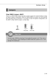
... the JBAT1 (Clear CMOS Jumper ) to clear data. 1 JBAT1 1 1 3 Keep Data 3 Clear Data Important You can automatically boot OS every time it will damage the mainboard. 2-19 Avoid clearing the CMOS while the system is turned on ; Hardware Setup Jumpers Clear CMOS Jumper: JBAT1 There is off. With the CMOS RAM...
... the JBAT1 (Clear CMOS Jumper ) to clear data. 1 JBAT1 1 1 3 Keep Data 3 Clear Data Important You can automatically boot OS every time it will damage the mainboard. 2-19 Avoid clearing the CMOS while the system is turned on ; Hardware Setup Jumpers Clear CMOS Jumper: JBAT1 There is off. With the CMOS RAM...
User Guide
Page 36
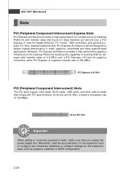
.... PCI Express x16 Slot PCI (Peripheral Component Interconnect) Slots The PCI slots support LAN cards, SCSI cards, USB cards, and other sophisticated applications. MS-7267 Mainboard Slots PCI (Peripheral Component Interconnect) Express Slots PCI Express architecture provides a high performance I /O. Moreover, PCI Express architecture provides a high performance graphics infrastructure for Desktop Platforms...
.... PCI Express x16 Slot PCI (Peripheral Component Interconnect) Slots The PCI slots support LAN cards, SCSI cards, USB cards, and other sophisticated applications. MS-7267 Mainboard Slots PCI (Peripheral Component Interconnect) Express Slots PCI Express architecture provides a high performance I /O. Moreover, PCI Express architecture provides a high performance graphics infrastructure for Desktop Platforms...


