User Guide
Page 8
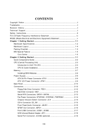
...) Statement v Chapter 1 Getting Started 1-1 Mainboard Specifications 1-2 Mainboard Layout 1-4 Packing Checklist 1-4 MSI Special Feature 1-6 Core Center 1-6 Chapter 2 Getting Started 1-1 Quick Components Guide 2-2 CPU (Central Processing Unit 2-3 Introduction to LGA 775 CPU 2-3 CPU & Cooler Installation 2-4 Memory ...2-7 Installing DDRII Modules 2-8 Power Supply ...2-9 ATX 24-Pin Power Connector: ATX1 2-9 ATX 12V Power Connector: JPW 1 2-9 Back Panel ...2-10 Connectors ...2-12 Floppy...
...) Statement v Chapter 1 Getting Started 1-1 Mainboard Specifications 1-2 Mainboard Layout 1-4 Packing Checklist 1-4 MSI Special Feature 1-6 Core Center 1-6 Chapter 2 Getting Started 1-1 Quick Components Guide 2-2 CPU (Central Processing Unit 2-3 Introduction to LGA 775 CPU 2-3 CPU & Cooler Installation 2-4 Memory ...2-7 Installing DDRII Modules 2-8 Power Supply ...2-9 ATX 24-Pin Power Connector: ATX1 2-9 ATX 12V Power Connector: JPW 1 2-9 Back Panel ...2-10 Connectors ...2-12 Floppy...
User Guide
Page 11
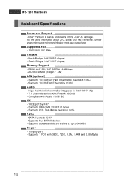
... Audio - Supports PIO, Bus Master operation mode SATA - Supports 1 FDD with Azalia 1.0 SPEC IDE - 1 IDE port by ICH7 - For the latest information about CPU, please visit http://www.msi.com.tw/ program/products/mainboard/mbd/pro_mbd_cpu_support.php Supported FSB - 1066/ 800/ 533 MHz Chipset - South Bridge: Intel® ICH7 chipset Memory Support...
... Audio - Supports PIO, Bus Master operation mode SATA - Supports 1 FDD with Azalia 1.0 SPEC IDE - 1 IDE port by ICH7 - For the latest information about CPU, please visit http://www.msi.com.tw/ program/products/mainboard/mbd/pro_mbd_cpu_support.php Supported FSB - 1066/ 800/ 533 MHz Chipset - South Bridge: Intel® ICH7 chipset Memory Support...
User Guide
Page 15
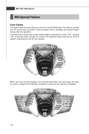
... and system status during real time operation. The utility is a new utility you click the red triangles in the CD-ROM disk. MS-7267 Mainboard MSI Special Feature Core Center The Core Center is just like your PC doctor that can find in the left side it shows the current PC...
... and system status during real time operation. The utility is a new utility you click the red triangles in the CD-ROM disk. MS-7267 Mainboard MSI Special Feature Core Center The Core Center is just like your PC doctor that can find in the left side it shows the current PC...
User Guide
Page 16
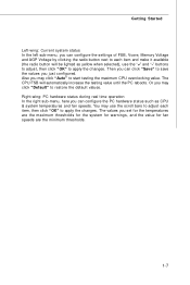
... temperatures and fan speeds. The values you may click "Default" to start testing the maximum CPU overclocking value. Right-wing: PC hardware status during real time operation In the right sub-menu, here you can click "Save" to save the values ...
... temperatures and fan speeds. The values you may click "Default" to start testing the maximum CPU overclocking value. Right-wing: PC hardware status during real time operation In the right sub-menu, here you can click "Save" to save the values ...
User Guide
Page 19
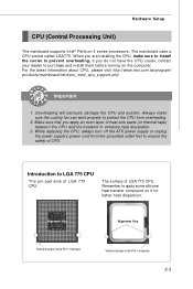
... Pin 1 indicator Yellow triangle is the Pin 1 indicator 2-3 The mainboard uses a CPU socket called LGA775. For the latest information about CPU, please visit http://www.msi.com.tw/program/ products/mainboard/mbd/pro_mbd_cpu_support.php Important 1. While replacing the CPU, always turn off the ATX power supply or unplug the power supply's power cord from overheating...
... Pin 1 indicator Yellow triangle is the Pin 1 indicator 2-3 The mainboard uses a CPU socket called LGA775. For the latest information about CPU, please visit http://www.msi.com.tw/program/ products/mainboard/mbd/pro_mbd_cpu_support.php Important 1. While replacing the CPU, always turn off the ATX power supply or unplug the power supply's power cord from overheating...
User Guide
Page 20
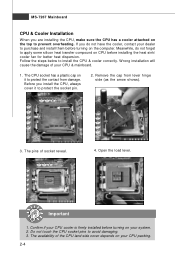
... Open the load lever. Confirm if your CPU cooler is firmly installed before turning on your system. 2. Do not touch the CPU socket pins to install the CPU & cooler correctly. The availability of the CPU land side cover depends on your CPU packing. 2-4 Remove the cap from damage. ... overheating. W rong installation will cause the damage of socket reveal. 4. MS-7267 Mainboard CPU & Cooler Installation W hen you are installing the CPU, make sure the CPU has a cooler attached on CPU before installing the heat sink/ cooler fan for better heat dispersion. If you do not ...
... Open the load lever. Confirm if your CPU cooler is firmly installed before turning on your system. 2. Do not touch the CPU socket pins to install the CPU & cooler correctly. The availability of the CPU land side cover depends on your CPU packing. 2-4 Remove the cap from damage. ... overheating. W rong installation will cause the damage of socket reveal. 4. MS-7267 Mainboard CPU & Cooler Installation W hen you are installing the CPU, make sure the CPU has a cooler attached on CPU before installing the heat sink/ cooler fan for better heat dispersion. If you do not ...

User Guide
Page 21
After confirming the CPU direction for correct mating, put down the CPU in the socket housing frame. Lift the load lever up and open the load plate. 6. If not, take out the CPU with pure vertical motion and reinstall. 8. Note that the alignment keys are matched. Visually inspect if the CPU is seated well into the socket. alignment key 7. Hardware Setup 5. Cover the load plate onto the p ac kage. 2-5 Be sure to grasp on the edge of the CPU base.
After confirming the CPU direction for correct mating, put down the CPU in the socket housing frame. Lift the load lever up and open the load plate. 6. If not, take out the CPU with pure vertical motion and reinstall. 8. Note that the alignment keys are matched. Visually inspect if the CPU is seated well into the socket. alignment key 7. Hardware Setup 5. Cover the load plate onto the p ac kage. 2-5 Be sure to grasp on the edge of the CPU base.
User Guide
Page 22
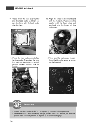
... switch (refer to the correct direction marked on the mainboard with the plastic cap covered (shown in BIOS (Chapter 3) for the CPU temperature. 2. Whenever CPU is not installed, always protect your CPU socket pin with the heatsink. locking switch Important 1. MS-7267 Mainboard 9. Press the four hooks down the cooler until its four...
... switch (refer to the correct direction marked on the mainboard with the plastic cap covered (shown in BIOS (Chapter 3) for the CPU temperature. 2. Whenever CPU is not installed, always protect your CPU socket pin with the heatsink. locking switch Important 1. MS-7267 Mainboard 9. Press the four hooks down the cooler until its four...
User Guide
Page 25
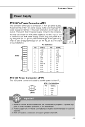
...OK 20 Res 9 5VSB 21 +5V 10 +12V 22 +5V 12 11 +12V 12 +3.3V 23 +5V 24 GND pin 13 pin 12 ATX 12V Power Connector: JPW1 This 12V power connector is highly recommended for system stability. 3. Then push down the power supply firmly into the connector. ...Power supply of 350 watts (and above) is used to provide power to the CPU. JPW1 Pin Definition 3 4 1 2 JPW1 PIN SIGNAL 1 GND 2 GND 3 12V 4 12V Important 1. Hardware Setup Power Supply ATX 24-Pin Power Connector: ATX1 This connector allows you like to use the 20-pin...
...OK 20 Res 9 5VSB 21 +5V 10 +12V 22 +5V 12 11 +12V 12 +3.3V 23 +5V 24 GND pin 13 pin 12 ATX 12V Power Connector: JPW1 This 12V power connector is highly recommended for system stability. 3. Then push down the power supply firmly into the connector. ...Power supply of 350 watts (and above) is used to provide power to the CPU. JPW1 Pin Definition 3 4 1 2 JPW1 PIN SIGNAL 1 GND 2 GND 3 12V 4 12V Important 1. Hardware Setup Power Supply ATX 24-Pin Power Connector: ATX1 This connector allows you like to use the 20-pin...
User Guide
Page 30
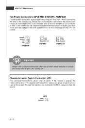
... enter the BIOS utility and clear the record. Chassis Intrusion Switch Connector: JCI1 This connector connects to the recommended CPU fans at Intel® official website or consult the vendors for proper CPU cooling fan. MS-7267 Mainboard Fan Power Connectors: CPUFAN1, SYSFAN1, PWRFAN1 The fan power connectors support system cooling fan... SYSFAN1 GND +12V SENSOR PWRFAN1 Important Please refer to a 2-pin chassis switch. The system will be connected to the connectors, always take advantage of the CPU fan c on tr ol .
... enter the BIOS utility and clear the record. Chassis Intrusion Switch Connector: JCI1 This connector connects to the recommended CPU fans at Intel® official website or consult the vendors for proper CPU cooling fan. MS-7267 Mainboard Fan Power Connectors: CPUFAN1, SYSFAN1, PWRFAN1 The fan power connectors support system cooling fan... SYSFAN1 GND +12V SENSOR PWRFAN1 Important Please refer to a 2-pin chassis switch. The system will be connected to the connectors, always take advantage of the CPU fan c on tr ol .
User Guide
Page 44
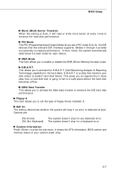
... the hard disks. The system doesn't stop for the IDE devices that monitors your system (read or write more sector at boot. It shows the CPU information, BIOS version and memory status of floppy drives installed. S.M.A.R.T is a utility that the onboard IDE interface supports. S.M .A.R.T . PIO Mode The PIO (Programmed Input/Output...
... the hard disks. The system doesn't stop for the IDE devices that monitors your system (read or write more sector at boot. It shows the CPU information, BIOS version and memory status of floppy drives installed. S.M.A.R.T is a utility that the onboard IDE interface supports. S.M .A.R.T . PIO Mode The PIO (Programmed Input/Output...
User Guide
Page 45
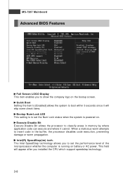
... power. W hen a malicious worm attempts to insert code in memory by where application code can execute and where it will appear after you installed the CPU which support speedstep technology. 3-8
... power. W hen a malicious worm attempts to insert code in memory by where application code can execute and where it will appear after you installed the CPU which support speedstep technology. 3-8
User Guide
Page 46
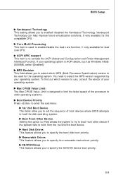
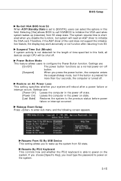
Hard Disk Drives This feature allows you to enabled/ disabled the Vanderpool Technology. It only available for the compatible CPU. If your operating system is used for the operating system. You need to select the MPS version supported by your operating system. Vanderpool... device boot priority. BIOS Setup Vanderpool Technology This setting allows you to specify the hard disk boot priority. It only available for dual core CPU. MPS Revision This field allows you to specify the CD/DVD device boot priority. 3-9 Removable Drives This feature allows you to set the ...
Hard Disk Drives This feature allows you to enabled/ disabled the Vanderpool Technology. It only available for the compatible CPU. If your operating system is used for the operating system. You need to select the MPS version supported by your operating system. Vanderpool... device boot priority. BIOS Setup Vanderpool Technology This setting allows you to specify the hard disk boot priority. It only available for dual core CPU. MPS Revision This field allows you to specify the CD/DVD device boot priority. 3-9 Removable Drives This feature allows you to set the ...
User Guide
Page 51
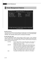
... W indows 98SE, W indows ME and W indows 2000, you can choose to enter the Standby mode in formation of this state, no system context is lost (CPU or chipset) and hardware maintains all system context. MS-7267 Mainboard Power Management Features ACPI Function This item is to save energy.
... W indows 98SE, W indows ME and W indows 2000, you can choose to enter the Standby mode in formation of this state, no system context is lost (CPU or chipset) and hardware maintains all system context. MS-7267 Mainboard Power Management Features ACPI Function This item is to save energy.
User Guide
Page 52
... state. If you choose [Specific Key], you to initialize the VGA card. Settings are : [Power Off] Leaves the computer in this field, all devices except CPU will need an AGP driver to wake up (resumes) from S3 W hen ACPI Standby State is set to configure the Power Button function. The system...
... state. If you choose [Specific Key], you to initialize the VGA card. Settings are : [Power Off] Leaves the computer in this field, all devices except CPU will need an AGP driver to wake up (resumes) from S3 W hen ACPI Standby State is set to configure the Power Button function. The system...
User Guide
Page 56
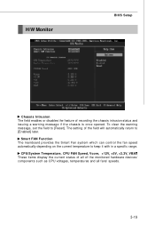
... specific range. H/W Monitor BIOS Setup Chassis Intrusion The field enables or disables the feature of the monitored hardware devices/ components such as CPU voltages, temperatures and all fans' speeds. 3-19 Smart FAN Function The mainboard provides the Smart Fan system which can control the fan... speed automatically depending on the current temperature to [Reset]. CPU/System Temperature, CPU FAN Speed, Vcore, +12V, +5V, +3.3V, VBAT These items display the current status of all of recording the chassis ...
... specific range. H/W Monitor BIOS Setup Chassis Intrusion The field enables or disables the feature of the monitored hardware devices/ components such as CPU voltages, temperatures and all fans' speeds. 3-19 Smart FAN Function The mainboard provides the Smart Fan system which can control the fan... speed automatically depending on the current temperature to [Reset]. CPU/System Temperature, CPU FAN Speed, Vcore, +12V, +5V, +3.3V, VBAT These items display the current status of all of recording the chassis ...
User Guide
Page 57
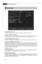
... which had been adjusted. Setting to this frequency. DRAM Frequency User can increase the DDR speed. MS-7267 Mainboard Cell_Menu Adjusted CPU Clock This item shows the CPU clock which had been adjusted. Configure DRAM Timing by the SPD (Serial Presence Detect) EEPROM on the DRAM module. Read only... allows users to configure the DRAM timings and the following related items to be determined by adjusting the FSB clock to select the CPU Front Side Bus clock frequency (in MHz) and overclock the processor by BIOS based on the configurations on the system. Read only. Adjust...
... which had been adjusted. Setting to this frequency. DRAM Frequency User can increase the DDR speed. MS-7267 Mainboard Cell_Menu Adjusted CPU Clock This item shows the CPU clock which had been adjusted. Configure DRAM Timing by the SPD (Serial Presence Detect) EEPROM on the DRAM module. Read only... allows users to configure the DRAM timings and the following related items to be determined by adjusting the FSB clock to select the CPU Front Side Bus clock frequency (in MHz) and overclock the processor by BIOS based on the configurations on the system. Read only. Adjust...

