
User Guide
Page 4
... for compliance could void the user's authority to operate the equipment. This equipment generates, uses and can be used in a residential installation. Micro-Star International MS-7507 This device complies with the limits for help. FCC-B Radio Frequency Interference Statement T h is eq uip men t h as been tested and found to comply with...
... for compliance could void the user's authority to operate the equipment. This equipment generates, uses and can be used in a residential installation. Micro-Star International MS-7507 This device complies with the limits for help. FCC-B Radio Frequency Interference Statement T h is eq uip men t h as been tested and found to comply with...
User Guide
Page 10
Getting Started Chapter 1 Getting Started Thank you for optimal system efficiency. Designed to fit the advanced Intel® Core 2 Duo/Pentium/Celeron LGA775 processor, the 945GCM7 Series deliver a high performance and professional desktop platform solution. 1-1 The 945GCM7 Series mainboards are based on Intel® 945GC & ICH7/ICH7R chipsets for choosing the 945GCM7 Series (MS-7507 v1.X) Micro-ATX mainboard.
Getting Started Chapter 1 Getting Started Thank you for optimal system efficiency. Designed to fit the advanced Intel® Core 2 Duo/Pentium/Celeron LGA775 processor, the 945GCM7 Series deliver a high performance and professional desktop platform solution. 1-1 The 945GCM7 Series mainboards are based on Intel® 945GC & ICH7/ICH7R chipsets for choosing the 945GCM7 Series (MS-7507 v1.X) Micro-ATX mainboard.
User Guide
Page 11
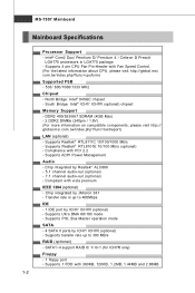
... ICH7/ ICH7R (optional) - Supports Ultra DMA 66/100 mode - Supports 1 FDD with Fan Speed Control. (For the latest information about CPU, please visit http://global.msi. DDR2 400/533/667 SDRAM (4GB Max) - 2 DDR2 DIMMs (240pin / 1.8V) (For more information on compatible components, please visit http:// glob al. Supports Realtek®... processors in LGA775 package. - Compliant with PCI 2.2 - Supports transfer rate up to 300 MB/s RAID (optional) - SATA1~4 support RAID 0/ 1/ 0+1 (for ICH7R only) Floppy - 1 floppy port - MS-7507 Mainboard Mainboard Specifications Processor Support -
... ICH7/ ICH7R (optional) - Supports Ultra DMA 66/100 mode - Supports 1 FDD with Fan Speed Control. (For the latest information about CPU, please visit http://global.msi. DDR2 400/533/667 SDRAM (4GB Max) - 2 DDR2 DIMMs (240pin / 1.8V) (For more information on compatible components, please visit http:// glob al. Supports Realtek®... processors in LGA775 package. - Compliant with PCI 2.2 - Supports transfer rate up to 300 MB/s RAID (optional) - SATA1~4 support RAID 0/ 1/ 0+1 (for ICH7R only) Floppy - 1 floppy port - MS-7507 Mainboard Mainboard Specifications Processor Support -
User Guide
Page 13
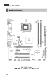
MS-7507 Mainboard Mainboard Layout Top : mouse Bottom:keyboard CPUFAN1 Parallel port Bottom: COM port VGA port ATX1 JPW1 T: 1394 port(optional) B: USB ports Top: LAN Jack ... IDE1 DIMM2 SATA4 DIMM1 RTM 876-665 BATT + Intel ICH7/ ICH7R(optional) JMicron 381 (optional) JFP2 SATA1 SATA2 FDD 1 J1394_1(optional) JBAT1 JFP1 JUSB1 JUSB2 945GCM7 Series (MS-7507 v1.X) Micro-ATX Mainboard 1-4 SATA3
MS-7507 Mainboard Mainboard Layout Top : mouse Bottom:keyboard CPUFAN1 Parallel port Bottom: COM port VGA port ATX1 JPW1 T: 1394 port(optional) B: USB ports Top: LAN Jack ... IDE1 DIMM2 SATA4 DIMM1 RTM 876-665 BATT + Intel ICH7/ ICH7R(optional) JMicron 381 (optional) JFP2 SATA1 SATA2 FDD 1 J1394_1(optional) JBAT1 JFP1 JUSB1 JUSB2 945GCM7 Series (MS-7507 v1.X) Micro-ATX Mainboard 1-4 SATA3
User Guide
Page 18
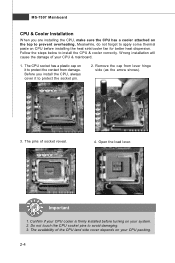
... your CPU packing. 2-4 Remove the cap from damage. Open the load lever. The availability of the CPU land side cover depends on your CPU & mainboard. 1. MS-7507 Mainboard CPU & Cooler Installation W hen you install the CPU, always cover it to prevent overheating. W rong installation will cause the damage of socket reveal. 4. Do...
... your CPU packing. 2-4 Remove the cap from damage. Open the load lever. The availability of the CPU land side cover depends on your CPU & mainboard. 1. MS-7507 Mainboard CPU & Cooler Installation W hen you install the CPU, always cover it to prevent overheating. W rong installation will cause the damage of socket reveal. 4. Do...
User Guide
Page 20
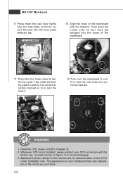
.... 2-6 Press down to the correct direction marked on the mainboard with the heatsink. The appearance of the mainboard. 11. Mainboard photos shown in BIOS (Chapter 3). 2. MS-7507 Mainboard 9. locking switch Important 1.
.... 2-6 Press down to the correct direction marked on the mainboard with the heatsink. The appearance of the mainboard. 11. Mainboard photos shown in BIOS (Chapter 3). 2. MS-7507 Mainboard 9. locking switch Important 1.
User Guide
Page 22
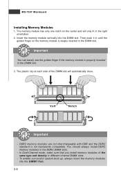
... channel DIMM slots. - In Dual-Channel mode, make sure that you install memory modules of the DIMM slot will only fit in the DIMM slot. 3. MS-7507 Mainboard Installing Memory Modules 1. Insert the memory module vertically into the DIM M1 first. 2-8 Then push it in until the golden finger on the center...
... channel DIMM slots. - In Dual-Channel mode, make sure that you install memory modules of the DIMM slot will only fit in the DIMM slot. 3. MS-7507 Mainboard Installing Memory Modules 1. Insert the memory module vertically into the DIM M1 first. 2-8 Then push it in until the golden finger on the center...
User Guide
Page 24
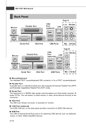
.... You can attach a serial mouse or other USB-compatible devices. 2-10 USB Port The USB (Universal Serial Bus) port is for a PS/2® mouse/keyboard. MS-7507 Mainboard Back Panel Mouse Keyboard Parallel Port 1394 Port (optional) Type A L-In RS-Out LAN L-Out CS-Out Serial Port VGA Port Mouse Parallel Port...
.... You can attach a serial mouse or other USB-compatible devices. 2-10 USB Port The USB (Universal Serial Bus) port is for a PS/2® mouse/keyboard. MS-7507 Mainboard Back Panel Mouse Keyboard Parallel Port 1394 Port (optional) Type A L-In RS-Out LAN L-Out CS-Out Serial Port VGA Port Mouse Parallel Port...
User Guide
Page 26
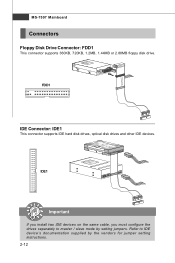
MS-7507 Mainboard Connectors Floppy Disk Drive Connector: FDD1 This connector supports 360KB, 720KB, 1.2MB, 1.44MB or 2.88MB floppy disk drive. Refer to master / slave mode by the vendors for jumper setting instructions. 2-12 FDD1 IDE Connector: IDE1 This connector supports IDE hard disk drives, optical disk drives and other IDE devices. IDE1 Important If you install two IDE devices on the same cable, you must configure the drives separately to IDE device's documentation supplied by setting jumpers.
MS-7507 Mainboard Connectors Floppy Disk Drive Connector: FDD1 This connector supports 360KB, 720KB, 1.2MB, 1.44MB or 2.88MB floppy disk drive. Refer to master / slave mode by the vendors for jumper setting instructions. 2-12 FDD1 IDE Connector: IDE1 This connector supports IDE hard disk drives, optical disk drives and other IDE devices. IDE1 Important If you install two IDE devices on the same cable, you must configure the drives separately to IDE device's documentation supplied by setting jumpers.
User Guide
Page 28
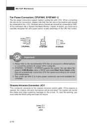
... temperature. 3. Fan cooler set with +12V. the black wire is the positive and should be connected to the connectors, always note that will be activated. MS-7507 Mainboard Fan Power Connectors: CPUFAN1, SYSFAN1~2 The fan power connectors support system cooling fan with 3 or 4 pins power connector are both available for proper CPU...
... temperature. 3. Fan cooler set with +12V. the black wire is the positive and should be connected to the connectors, always note that will be activated. MS-7507 Mainboard Fan Power Connectors: CPUFAN1, SYSFAN1~2 The fan power connectors support system cooling fan with 3 or 4 pins power connector are both available for proper CPU...
User Guide
Page 30
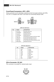
MS-7507 Mainboard Front Panel Connectors: JFP1, JFP2 These connectors are for external audio input. The JFP1 is provided for electrical connection to GND Reserved. Switch - HDD 1 +...
MS-7507 Mainboard Front Panel Connectors: JFP1, JFP2 These connectors are for external audio input. The JFP1 is provided for electrical connection to GND Reserved. Switch - HDD 1 +...
User Guide
Page 32
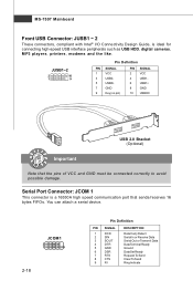
... 3 USB0- 5 USB0+ 7 GND 9 Key (no pin) PIN SIGNAL 2 VCC 4 USB1- 6 USB1+ 8 GND 10 USBOC USB 2.0 Bracket (Optional) Important Note that sends/receives 16 bytes FIFOs. MS-7507 Mainboard Front USB Connector: JUSB1 ~ 2 These connectors, compliant with Intel® I/O Connectivity Design Guide, is a 16550A high speed communication port that the pins of VCC...
... 3 USB0- 5 USB0+ 7 GND 9 Key (no pin) PIN SIGNAL 2 VCC 4 USB1- 6 USB1+ 8 GND 10 USBOC USB 2.0 Bracket (Optional) Important Note that sends/receives 16 bytes FIFOs. MS-7507 Mainboard Front USB Connector: JUSB1 ~ 2 These connectors, compliant with Intel® I/O Connectivity Design Guide, is a 16550A high speed communication port that the pins of VCC...
User Guide
Page 34
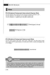
.... The PCI Express x 1 supports up to configure any necessary hardware or software settings for the expansion card, such as jumpers, switches or BIOS configuration. 2-20 MS-7507 Mainboard Slots PCI (Peripheral Component Interconnect) Express Slots The PCI Express slot supports the PCI Express interface expansion card.
.... The PCI Express x 1 supports up to configure any necessary hardware or software settings for the expansion card, such as jumpers, switches or BIOS configuration. 2-20 MS-7507 Mainboard Slots PCI (Peripheral Component Interconnect) Express Slots The PCI Express slot supports the PCI Express interface expansion card.
User Guide
Page 37
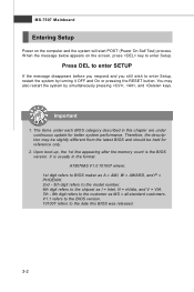
...digit refers to the model number. 6th digit refers to the chipset as I = Intel, N = nVidia, and V = VIA. 7th - 8th digit refers to the customer as MS = all standard customers. You may be slightly different from the latest BIOS and should be held for better system performance. Therefore, the description may also...by simultaneously pressing , , and keys. V1.1 refers to the BIOS version. 101007 refers to the date this chapter are under continuous update for reference only. 2. MS-7507 Mainboard Entering Setup Power on the screen, press key to enter Setup. It is the BIOS version.
...digit refers to the model number. 6th digit refers to the chipset as I = Intel, N = nVidia, and V = VIA. 7th - 8th digit refers to the customer as MS = all standard customers. You may be slightly different from the latest BIOS and should be held for better system performance. Therefore, the description may also...by simultaneously pressing , , and keys. V1.1 refers to the BIOS version. 101007 refers to the date this chapter are under continuous update for reference only. 2. MS-7507 Mainboard Entering Setup Power on the screen, press key to enter Setup. It is the BIOS version.
User Guide
Page 39
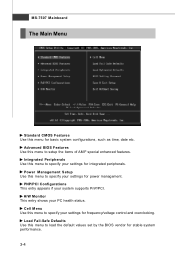
... specify your system supports PnP/PCI. Power Management Setup Use this menu to load the default values set by the BIOS vendor for integrated peripherals. MS-7507 Mainboard The Main Menu Standard CMOS Features Use this menu to setup the items of AMI® special enhanced features. Cell Menu Use this menu...
... specify your system supports PnP/PCI. Power Management Setup Use this menu to load the default values set by the BIOS vendor for integrated peripherals. MS-7507 Mainboard The Main Menu Standard CMOS Features Use this menu to setup the items of AMI® special enhanced features. Cell Menu Use this menu...
User Guide
Page 41
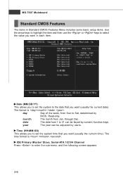
... keys to 31 can be keyed by BIOS. Date (MM:DD:YY) This allows you want (usually the current date). date The date from Jan. MS-7507 Mainboard Standard CMOS Features The items in each item.
... keys to 31 can be keyed by BIOS. Date (MM:DD:YY) This allows you want (usually the current date). date The date from Jan. MS-7507 Mainboard Standard CMOS Features The items in each item.
User Guide
Page 43
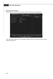
This sub-menu shows the CPU information, BIOS version and memory status of your system (read only). 3-8 MS-7507 Mainboard System Information Press to enter the sub-menu, and the following screen appears.
This sub-menu shows the CPU information, BIOS version and memory status of your system (read only). 3-8 MS-7507 Mainboard System Information Press to enter the sub-menu, and the following screen appears.
User Guide
Page 45
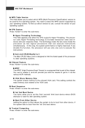
... operating system. If you disable the f unction, the processor will provide you with the means to get to boot from the 1st/ 2nd boot device. MS-7507 Mainboard MPS Table Version This field allows you to select which version to the VGA card. Set Limit CPUID MaxVal to 3 The Max CPUID Value...
... operating system. If you disable the f unction, the processor will provide you with the means to get to boot from the 1st/ 2nd boot device. MS-7507 Mainboard MPS Table Version This field allows you to select which version to the VGA card. Set Limit CPUID MaxVal to 3 The Max CPUID Value...
User Guide
Page 47
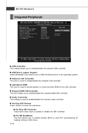
... These items allow users to enable/disable the onboard LAN controller. Onboard LAN Controller This item is used to enable or disable the IDE controller. MS-7507 Mainboard Integrated Peripherals USB Controller This setting allows you to invoke the Boot ROM of the LAN controller. LAN Option ROM This item is used...
... These items allow users to enable/disable the onboard LAN controller. Onboard LAN Controller This item is used to enable or disable the IDE controller. MS-7507 Mainboard Integrated Peripherals USB Controller This setting allows you to invoke the Boot ROM of the LAN controller. LAN Option ROM This item is used...
User Guide
Page 49
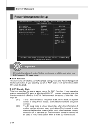
... information stored in memory will be used to activate the ACPI (Advanced Configuration and Power Management Interface) Function. If your BIOS supports S3 sleep mode. MS-7507 Mainboard Power Management Setup Important S3-related functions described in this section are : [S1] The S1 sleep mode is a low power state. ACPI Function This...
... information stored in memory will be used to activate the ACPI (Advanced Configuration and Power Management Interface) Function. If your BIOS supports S3 sleep mode. MS-7507 Mainboard Power Management Setup Important S3-related functions described in this section are : [S1] The S1 sleep mode is a low power state. ACPI Function This...


