

User Guide
Page 2
... of Phoenix Technologies Ltd. Revision History Revision V1.0 Revision History First release Date November 2007 Technical Support If a problem arises with your place of purchase or local distributor. Award® is a registered trademark of their respective owners. Copyright Notice The material in this document, but no solution can be obtained from the user's manual, please contact...
... of Phoenix Technologies Ltd. Revision History Revision V1.0 Revision History First release Date November 2007 Technical Support If a problem arises with your place of purchase or local distributor. Award® is a registered trademark of their respective owners. Copyright Notice The material in this document, but no solution can be obtained from the user's manual, please contact...
User Guide
Page 8
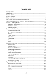
... Started 1-1 Mainboard Specifications 1-2 Mainboard Layout 1-4 Packing Checklist 1-5 Chapter 2. Hardware Setup 2-1 Quick Components Guide 2-2 CPU (Central Processing Unit 2-3 Memory ...2-7 Power Supply ...2-8 Back Panel ...2-9 Connectors ...2-11 Jumpers ...2-18 Slots ...2-19 Chapter 3 BIOS Setup 3-1 Entering Setup ...3-2 The Main Menu ...3-4 Standard CMOS Features 3-6 Advanced BIOS Features 3-9 Integrated Peripherals 3-11 Power Management Setup 3-13 PNP/PCI Configurations 3-15 H/W Monitor ...3-17 Cell Menu ...3-18 Load Fail-Safe/ Optimized Defaults 3-21 BIOS Setting Password...
... Started 1-1 Mainboard Specifications 1-2 Mainboard Layout 1-4 Packing Checklist 1-5 Chapter 2. Hardware Setup 2-1 Quick Components Guide 2-2 CPU (Central Processing Unit 2-3 Memory ...2-7 Power Supply ...2-8 Back Panel ...2-9 Connectors ...2-11 Jumpers ...2-18 Slots ...2-19 Chapter 3 BIOS Setup 3-1 Entering Setup ...3-2 The Main Menu ...3-4 Standard CMOS Features 3-6 Advanced BIOS Features 3-9 Integrated Peripherals 3-11 Power Management Setup 3-13 PNP/PCI Configurations 3-15 H/W Monitor ...3-17 Cell Menu ...3-18 Load Fail-Safe/ Optimized Defaults 3-21 BIOS Setting Password...
User Guide
Page 11
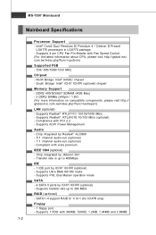
...300 MB/s RAID (optional) - Supports 4 pin CPU Fan Pin-Header with vista premium IEEE 1394 (optional) - South Bridge: Intel® ICH7/ ICH7R (optional) chipset Memory Support - Compliant with Fan Speed Control. (For the latest information about CPU, please visit http://global.msi. SATA1~4 support RAID 0/ 1/ 0+1 (for ICH7R only) Floppy - 1 floppy port - Supports 1 FDD with PCI 2.2 - Supports Realtek® RTL8101E 10/100 Mb/s (optional) - Supports ACPI Power Management Audio - Intel® Core2 Duo/ Pemtium D/ Pemtium 4 / Celeron D Presott LGA775 processors in LGA775 package...
...300 MB/s RAID (optional) - Supports 4 pin CPU Fan Pin-Header with vista premium IEEE 1394 (optional) - South Bridge: Intel® ICH7/ ICH7R (optional) chipset Memory Support - Compliant with Fan Speed Control. (For the latest information about CPU, please visit http://global.msi. SATA1~4 support RAID 0/ 1/ 0+1 (for ICH7R only) Floppy - 1 floppy port - Supports 1 FDD with PCI 2.2 - Supports Realtek® RTL8101E 10/100 Mb/s (optional) - Supports ACPI Power Management Audio - Intel® Core2 Duo/ Pemtium D/ Pemtium 4 / Celeron D Presott LGA775 processors in LGA775 package...

User Guide
Page 23
... Important 1. To connect the ATX 24-pin power supply, make sure the plug of the power supply is inserted in the proper orientation and the pins are connected to proper ATX power supplies to ensure stable operation of 350 watts (and above) is used to provide power to connect an ATX 24-pin power supply. Then push down the power supply firmly into the connector. Hardware Setup Power Supply ATX 24-Pin Power Connector: ATX1 This connector allows you to the CPU.
... Important 1. To connect the ATX 24-pin power supply, make sure the plug of the power supply is inserted in the proper orientation and the pins are connected to proper ATX power supplies to ensure stable operation of 350 watts (and above) is used to provide power to connect an ATX 24-pin power supply. Then push down the power supply firmly into the connector. Hardware Setup Power Supply ATX 24-Pin Power Connector: ATX1 This connector allows you to the CPU.
User Guide
Page 26
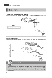
Refer to master / slave mode by the vendors for jumper setting instructions. 2-12 IDE1 Important If you install two IDE devices on the same cable, you must configure the drives separately to IDE device's documentation supplied by setting jumpers. FDD1 IDE Connector: IDE1 This connector supports IDE hard disk drives, optical disk drives and other IDE devices. MS-7507 Mainboard Connectors Floppy Disk Drive Connector: FDD1 This connector supports 360KB, 720KB, 1.2MB, 1.44MB or 2.88MB floppy disk drive.
Refer to master / slave mode by the vendors for jumper setting instructions. 2-12 IDE1 Important If you install two IDE devices on the same cable, you must configure the drives separately to IDE device's documentation supplied by setting jumpers. FDD1 IDE Connector: IDE1 This connector supports IDE hard disk drives, optical disk drives and other IDE devices. MS-7507 Mainboard Connectors Floppy Disk Drive Connector: FDD1 This connector supports 360KB, 720KB, 1.2MB, 1.44MB or 2.88MB floppy disk drive.
User Guide
Page 28
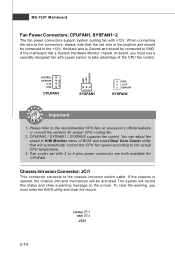
... actual CPU temperature. 3. Please refer to GND. CPUFAN1 / SYSFAN1 / SYSFAN2 supports fan control. The system will be connected to the chassis intrusion switch cable. If the mainboard has a System Hardware Monitor chipset on the screen. the black wire is opened, the chassis intrusion mechanism will record this status and show a warning message on -board, you must use a specially designed fan with speed sensor to take advantage of BIOS and install Dual Core Center utility...
... actual CPU temperature. 3. Please refer to GND. CPUFAN1 / SYSFAN1 / SYSFAN2 supports fan control. The system will be connected to the chassis intrusion switch cable. If the mainboard has a System Hardware Monitor chipset on the screen. the black wire is opened, the chassis intrusion mechanism will record this status and show a warning message on -board, you must use a specially designed fan with speed sensor to take advantage of BIOS and install Dual Core Center utility...
User Guide
Page 33
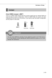
Then return to clear data. 3 3 1 JBAT1 1 Keep Data 1 Clear Data Important You can automatically boot OS every time it will damage the mainboard. 2-19 Avoid clearing the CMOS while the system is a CMOS RAM onboard that has a power supply from an external battery to keep the data of system configuration. If you want to clear the system configuration, set the jumper to 1-2 pin position. W ith the CMOS RAM, the system can clear CMOS by shorting 2-3 pin while the system is turned on ; it is off. Hardware Setup Jumper Clear CMOS Jumper: JBAT1 There is on .
Then return to clear data. 3 3 1 JBAT1 1 Keep Data 1 Clear Data Important You can automatically boot OS every time it will damage the mainboard. 2-19 Avoid clearing the CMOS while the system is a CMOS RAM onboard that has a power supply from an external battery to keep the data of system configuration. If you want to clear the system configuration, set the jumper to 1-2 pin position. W ith the CMOS RAM, the system can clear CMOS by shorting 2-3 pin while the system is turned on ; it is off. Hardware Setup Jumper Clear CMOS Jumper: JBAT1 There is on .
User Guide
Page 34
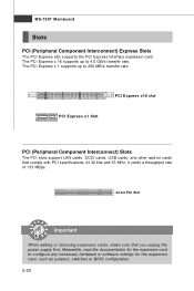
... the power supply first. At 32 bits and 33 MHz, it yields a throughput rate of 133 MBps. 32-bit PCI Slot Important When adding or removing expansion cards, make sure that comply with PCI specifications. Meanwhile, read the documentation for the expansion card, such as jumpers, switches or BIOS configuration. 2-20 The PCI Express x 1 supports up to 4.0 GB/s transfer rate. The PCI Express x 16 supports up to configure any necessary hardware or software settings...
... the power supply first. At 32 bits and 33 MHz, it yields a throughput rate of 133 MBps. 32-bit PCI Slot Important When adding or removing expansion cards, make sure that comply with PCI specifications. Meanwhile, read the documentation for the expansion card, such as jumpers, switches or BIOS configuration. 2-20 The PCI Express x 1 supports up to 4.0 GB/s transfer rate. The PCI Express x 16 supports up to configure any necessary hardware or software settings...
User Guide
Page 42
... LBA mode disabled. This gives you to the IDE/ SATA connector on the mainboard. IImmppoorrttaanntt Primary IDE M aster/ Slave, Serial-ATA 1/2/3/4 Channel are appearing when you connected to a safe place before the hard disk becomes offline. DM A M ode Select DMA Mode. Setting to Auto enables LBA mode if the device supports it and the devices is going to fail to the SATA connector. Hard Disk S.M.A.R.T. S.M.A.R.T is a utility that you connect the HD devices to set the type of floppy drives installed. Available options: [None...
... LBA mode disabled. This gives you to the IDE/ SATA connector on the mainboard. IImmppoorrttaanntt Primary IDE M aster/ Slave, Serial-ATA 1/2/3/4 Channel are appearing when you connected to a safe place before the hard disk becomes offline. DM A M ode Select DMA Mode. Setting to Auto enables LBA mode if the device supports it and the devices is going to fail to the SATA connector. Hard Disk S.M.A.R.T. S.M.A.R.T is a utility that you connect the HD devices to set the type of floppy drives installed. Available options: [None...
User Guide
Page 45
... setting controls the exact memory size shared to enter the sub-menu: 3-10 Boot From Other Device Setting the option to [Yes] allows the system to try to boot from the 1st/ 2nd boot device. To find out which MPS (Multi-Processor Specification) version to the onboard VGA card. Set Limit CPUID MaxVal to 3 The Max CPUID Value Limit is designed to limit the listed speed of the processor to older operating systems. Chipset Feature...
... setting controls the exact memory size shared to enter the sub-menu: 3-10 Boot From Other Device Setting the option to [Yes] allows the system to try to boot from the 1st/ 2nd boot device. To find out which MPS (Multi-Processor Specification) version to the onboard VGA card. Set Limit CPUID MaxVal to 3 The Max CPUID Value Limit is designed to limit the listed speed of the processor to older operating systems. Chipset Feature...
User Guide
Page 46
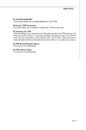
... allows you to enable/disable the TCG/TPM. TPM Enable/Disable Status This item is not configurable. 3-11 BIOS Setup TCG/TPM SUPPORT This setting allows you to enable or disable the TPM security chip. TPM Owner Status This item is not configurable. Clearing the TPM This item allows you want to clear the user information in the TPM security chip. Use the left / right arrow key to select...
... allows you to enable/disable the TCG/TPM. TPM Enable/Disable Status This item is not configurable. 3-11 BIOS Setup TCG/TPM SUPPORT This setting allows you to enable or disable the TPM security chip. TPM Owner Status This item is not configurable. Clearing the TPM This item allows you want to clear the user information in the TPM security chip. Use the left / right arrow key to select...
User Guide
Page 47
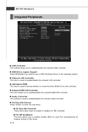
... allows you to enable/disable the onboard USB controller. LAN Option ROM This item is used to decide whether to invoke the Boot ROM of the LAN controller. Audio Controller This setting is used to enable/disable the onboard audio controller. MS-7507 Mainboard Integrated Peripherals USB Controller This setting allows you to enable/disable the onboard IEEE1394 controller. On-Chip ATA Devices Press to enter the sub-menu: On-Chip IDE Controller These items allow users to enable/disable the onboard LAN controller. Onboard LAN Controller This item is used PCI busmastering for reading...
... allows you to enable/disable the onboard USB controller. LAN Option ROM This item is used to decide whether to invoke the Boot ROM of the LAN controller. Audio Controller This setting is used to enable/disable the onboard audio controller. MS-7507 Mainboard Integrated Peripherals USB Controller This setting allows you to enable/disable the onboard IEEE1394 controller. On-Chip ATA Devices Press to enter the sub-menu: On-Chip IDE Controller These items allow users to enable/disable the onboard LAN controller. Onboard LAN Controller This item is used PCI busmastering for reading...
User Guide
Page 48
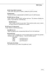
... enter the AHCI settings sub-menu. These submenu allow users to enable/disable the RAID function for the first serial port. Parallel Port There is used to enable or disable the SATA controller. It has the following options: [Disabled] [3BC] Line Printer port 0 [278] Line Printer port 2 [378] Line Printer port 1 Parallel Port M ode This item allows you to the system. The submenu displays the status of auto detection of devices connected to select the parallel port mode...
... enter the AHCI settings sub-menu. These submenu allow users to enable/disable the RAID function for the first serial port. Parallel Port There is used to enable or disable the SATA controller. It has the following options: [Disabled] [3BC] Line Printer port 0 [278] Line Printer port 2 [378] Line Printer port 1 Parallel Port M ode This item allows you to the system. The submenu displays the status of auto detection of devices connected to select the parallel port mode...
User Guide
Page 50
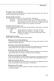
... is used to enable or disable the feature of booting up the system from the power saving modes through any event on PCIE device. Wakeup Event Setup Press and the following sub-menu appears. Settings are : [Off] Always leaves the computer in the power off . Settings are : [On/ Off] The power button functions as normal power off button. [Suspend] W hen you press the power button, the computer enters the suspend/sleep mode...
... is used to enable or disable the feature of booting up the system from the power saving modes through any event on PCIE device. Wakeup Event Setup Press and the following sub-menu appears. Settings are : [Off] Always leaves the computer in the power off . Settings are : [On/ Off] The power button functions as normal power off button. [Suspend] W hen you press the power button, the computer enters the suspend/sleep mode...
User Guide
Page 51
... This item controls how long each PCI slot. 3-16 W hen set the item to operate at speeds nearing the speed the CPU itself uses when communicating with its special components. PCI Slot 1/ 2 IRQ These items specify the IRQ line for each PCI device can conduct transactions for a longer time and thus improve the effective PCI bandwidth. Primary Graphic's Adapter This setting specifies which allows I/O devices to higher...
... This item controls how long each PCI slot. 3-16 W hen set the item to operate at speeds nearing the speed the CPU itself uses when communicating with its special components. PCI Slot 1/ 2 IRQ These items specify the IRQ line for each PCI device can conduct transactions for a longer time and thus improve the effective PCI bandwidth. Primary Graphic's Adapter This setting specifies which allows I/O devices to higher...
User Guide
Page 53
... smart fan function will be activated. CPU Min.FAN speed(%) This item allows users to speed up for the CPU f an . To clear the warning message, set the field to keep it with in a specific range. MS-7507 Mainboard H/W Monitor Chassis Intrusion The field enables or disables the feature of the monitored hardware devices/ components such as CPU voltage, temperatures and all fans' speeds. 3-18 PC Health Status CPU/ System Temperature, CPU FAN/ SYS FAN1/ SYS FAN2 Speed, CPU...
... smart fan function will be activated. CPU Min.FAN speed(%) This item allows users to speed up for the CPU f an . To clear the warning message, set the field to keep it with in a specific range. MS-7507 Mainboard H/W Monitor Chassis Intrusion The field enables or disables the feature of the monitored hardware devices/ components such as CPU voltage, temperatures and all fans' speeds. 3-18 PC Health Status CPU/ System Temperature, CPU FAN/ SYS FAN1/ SYS FAN2 Speed, CPU...
User Guide
Page 55
Auto Disable DIMM/PCI Frequency W hen set to Enabled for EMI reduction. But if you to select the PCIE frequency (in MHz). MS-7507 Mainboard DRAM CAS# Latency W hen the Configuration DRAM Timing by SPD sets to [Disabled], the field is allowed for the RAS to accumulate its charge before SDRAM starts a read from and write to a memory cell. If insufficient time is adjustable.This controls the CAS...
Auto Disable DIMM/PCI Frequency W hen set to Enabled for EMI reduction. But if you to select the PCIE frequency (in MHz). MS-7507 Mainboard DRAM CAS# Latency W hen the Configuration DRAM Timing by SPD sets to [Disabled], the field is allowed for the RAS to accumulate its charge before SDRAM starts a read from and write to a memory cell. If insufficient time is adjustable.This controls the CAS...
User Guide
Page 62
... Main Before using this utility. A-3 MB Click MB button to read current GPU temperature, GPU clock and memory clock of the MSI mainboard would be available. If you : only when installing the MSI V044 (V044 has to read current CPU temperature, FSB and CPU clock of mainboard will show below . DOT Click DOT button to execute the function. VGA Click VGA button to install with the version 8.26 or newer driver)/ V046 or V060 graphics card...
... Main Before using this utility. A-3 MB Click MB button to read current GPU temperature, GPU clock and memory clock of the MSI mainboard would be available. If you : only when installing the MSI V044 (V044 has to read current CPU temperature, FSB and CPU clock of mainboard will show below . DOT Click DOT button to execute the function. VGA Click VGA button to install with the version 8.26 or newer driver)/ V046 or V060 graphics card...
User Guide
Page 73
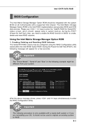
... used to migrate an existing system to enter the "Intel(R) RAID for a few seconds: Important The "Driver Model", "Serial #" and "Size" in system boot-up, during the POST (Power-On Self Test). Intel ICH7R SATA RAID BIOS Configuration The Intel Matrix Storage Manager Option ROM should be integrated with the system BIOS on all motherboards with a newly-built system or if you need to enable the RAID function in BIOS to enter the RAID Configuration Utility...
... used to migrate an existing system to enter the "Intel(R) RAID for a few seconds: Important The "Driver Model", "Serial #" and "Size" in system boot-up, during the POST (Power-On Self Test). Intel ICH7R SATA RAID BIOS Configuration The Intel Matrix Storage Manager Option ROM should be integrated with the system BIOS on all motherboards with a newly-built system or if you need to enable the RAID function in BIOS to enter the RAID Configuration Utility...

User Guide
Page 79
... Additional Device(s). 3. From the W indows XP/2000 Setup screen, press the key. The driver Intel(R) NH82801GR SATAII RAID Controller should appear. Important Please follow the instruction below to make an "Intel IAA RAID XP Driver For ICH7R (NH82801GR)" for ICH7R RAID controller is generated, press S to continue with installation. 6. Insert the MSI CD into drive A: and press . Insert the MSI CD into the CD-ROM drive. 2. Intel ICH7R SATA RAID Installing Software Install Driver...
... Additional Device(s). 3. From the W indows XP/2000 Setup screen, press the key. The driver Intel(R) NH82801GR SATAII RAID Controller should appear. Important Please follow the instruction below to make an "Intel IAA RAID XP Driver For ICH7R (NH82801GR)" for ICH7R RAID controller is generated, press S to continue with installation. 6. Insert the MSI CD into drive A: and press . Insert the MSI CD into the CD-ROM drive. 2. Intel ICH7R SATA RAID Installing Software Install Driver...

