
User Guide
Page 4
... a Class B digital device, pursuant to Part 15 of the FCC Rules. This equipment generates, uses and can be used in a residential installation. Micro-Star International MS-7507 This device complies with the emission limits. However, there is no guarantee that may not cause harmful interference, and (2) this device must be determined by...
... a Class B digital device, pursuant to Part 15 of the FCC Rules. This equipment generates, uses and can be used in a residential installation. Micro-Star International MS-7507 This device complies with the emission limits. However, there is no guarantee that may not cause harmful interference, and (2) this device must be determined by...
User Guide
Page 10
The 945GCM7 Series mainboards are based on Intel® 945GC & ICH7/ICH7R chipsets for choosing the 945GCM7 Series (MS-7507 v1.X) Micro-ATX mainboard. Designed to fit the advanced Intel® Core 2 Duo/Pentium/Celeron LGA775 processor, the 945GCM7 Series deliver a high performance and professional desktop platform solution. 1-1 Getting Started Chapter 1 Getting Started Thank you for optimal system efficiency.
The 945GCM7 Series mainboards are based on Intel® 945GC & ICH7/ICH7R chipsets for choosing the 945GCM7 Series (MS-7507 v1.X) Micro-ATX mainboard. Designed to fit the advanced Intel® Core 2 Duo/Pentium/Celeron LGA775 processor, the 945GCM7 Series deliver a high performance and professional desktop platform solution. 1-1 Getting Started Chapter 1 Getting Started Thank you for optimal system efficiency.
User Guide
Page 11
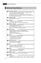
... Bridge: Intel® ICH7/ ICH7R (optional) chipset Memory Support - t w / index. Compliant with Fan Speed Control. (For the latest information about CPU, please visit http://global.msi. MS-7507 Mainboard Mainboard Specifications Processor Support - DDR2 400/533/667 SDRAM (4GB Max) - 2 DDR2 DIMMs (240pin / 1.8V) (For more information on compatible components, please visit http...
... Bridge: Intel® ICH7/ ICH7R (optional) chipset Memory Support - t w / index. Compliant with Fan Speed Control. (For the latest information about CPU, please visit http://global.msi. MS-7507 Mainboard Mainboard Specifications Processor Support - DDR2 400/533/667 SDRAM (4GB Max) - 2 DDR2 DIMMs (240pin / 1.8V) (For more information on compatible components, please visit http...
User Guide
Page 13
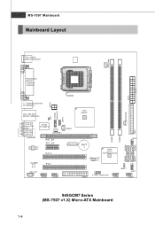
MS-7507 Mainboard Mainboard Layout Top : mouse Bottom:keyboard CPUFAN1 Parallel port Bottom: COM port VGA port ATX1 JPW1 T: 1394 port(optional) B: USB ports Top: LAN Jack ... IDE1 DIMM2 SATA4 DIMM1 RTM 876-665 BATT + Intel ICH7/ ICH7R(optional) JMicron 381 (optional) JFP2 SATA1 SATA2 FDD 1 J1394_1(optional) JBAT1 JFP1 JUSB1 JUSB2 945GCM7 Series (MS-7507 v1.X) Micro-ATX Mainboard 1-4 SATA3
MS-7507 Mainboard Mainboard Layout Top : mouse Bottom:keyboard CPUFAN1 Parallel port Bottom: COM port VGA port ATX1 JPW1 T: 1394 port(optional) B: USB ports Top: LAN Jack ... IDE1 DIMM2 SATA4 DIMM1 RTM 876-665 BATT + Intel ICH7/ ICH7R(optional) JMicron 381 (optional) JFP2 SATA1 SATA2 FDD 1 J1394_1(optional) JBAT1 JFP1 JUSB1 JUSB2 945GCM7 Series (MS-7507 v1.X) Micro-ATX Mainboard 1-4 SATA3
User Guide
Page 18
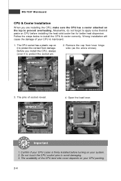
... correctly. Before you are installing the CPU, make sure the CPU has a cooler attached on the top to prevent overheating. Confirm if your CPU & mainboard. 1. MS-7507 Mainboard CPU & Cooler Installation W hen you install the CPU, always cover it to protect the contact from lever hinge side (as the arrow shows). 3. The...
... correctly. Before you are installing the CPU, make sure the CPU has a cooler attached on the top to prevent overheating. Confirm if your CPU & mainboard. 1. MS-7507 Mainboard CPU & Cooler Installation W hen you install the CPU, always cover it to protect the contact from lever hinge side (as the arrow shows). 3. The...
User Guide
Page 20
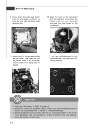
... the locking switch (refer to the correct direction marked on it) to fasten the cooler. Press the four hooks down to lock the h ook s . 12. MS-7507 Mainboard 9. Mainboard photos shown in this section are correctly inserted. Turn over the mainboard to avoid damaging. 3. locking switch Important 1. Align the holes on the...
... the locking switch (refer to the correct direction marked on it) to fasten the cooler. Press the four hooks down to lock the h ook s . 12. MS-7507 Mainboard 9. Mainboard photos shown in this section are correctly inserted. Turn over the mainboard to avoid damaging. 3. locking switch Important 1. Align the holes on the...
User Guide
Page 22
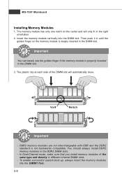
... the DDR2 standard is properly inserted in the right orientation. 2. To enable successful system boot-up, always insert the memory modules into the DIMM slot. MS-7507 Mainboard Installing Memory Modules 1. In Dual-Channel mode, make sure that you install memory modules of the DIMM slot will only fit in the DIMM...
... the DDR2 standard is properly inserted in the right orientation. 2. To enable successful system boot-up, always insert the memory modules into the DIMM slot. MS-7507 Mainboard Installing Memory Modules 1. In Dual-Channel mode, make sure that you install memory modules of the DIMM slot will only fit in the DIMM...
User Guide
Page 24
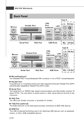
... The USB (Universal Serial Bus) port is a 16550A high speed communications port that supports Enhanced Parallel Port (EPP) and Extended Capabilities Parallel Port (ECP) mode. MS-7507 Mainboard Back Panel Mouse Keyboard Parallel Port 1394 Port (optional) Type A L-In RS-Out LAN L-Out CS-Out Serial Port VGA Port Mouse Parallel Port...
... The USB (Universal Serial Bus) port is a 16550A high speed communications port that supports Enhanced Parallel Port (EPP) and Extended Capabilities Parallel Port (ECP) mode. MS-7507 Mainboard Back Panel Mouse Keyboard Parallel Port 1394 Port (optional) Type A L-In RS-Out LAN L-Out CS-Out Serial Port VGA Port Mouse Parallel Port...
User Guide
Page 26
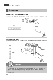
FDD1 IDE Connector: IDE1 This connector supports IDE hard disk drives, optical disk drives and other IDE devices. MS-7507 Mainboard Connectors Floppy Disk Drive Connector: FDD1 This connector supports 360KB, 720KB, 1.2MB, 1.44MB or 2.88MB floppy disk drive. IDE1 Important If you install two IDE devices on the same cable, you must configure the drives separately to IDE device's documentation supplied by setting jumpers. Refer to master / slave mode by the vendors for jumper setting instructions. 2-12
FDD1 IDE Connector: IDE1 This connector supports IDE hard disk drives, optical disk drives and other IDE devices. MS-7507 Mainboard Connectors Floppy Disk Drive Connector: FDD1 This connector supports 360KB, 720KB, 1.2MB, 1.44MB or 2.88MB floppy disk drive. IDE1 Important If you install two IDE devices on the same cable, you must configure the drives separately to IDE device's documentation supplied by setting jumpers. Refer to master / slave mode by the vendors for jumper setting instructions. 2-12
User Guide
Page 28
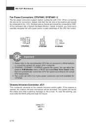
... intrusion mechanism will automatically control the CPU fan speed according to the recommended CPU fans at processor's official website or consult the vendors for CPUFAN. MS-7507 Mainboard Fan Power Connectors: CPUFAN1, SYSFAN1~2 The fan power connectors support system cooling fan with 3 or 4 pins power connector are both available for proper CPU...
... intrusion mechanism will automatically control the CPU fan speed according to the recommended CPU fans at processor's official website or consult the vendors for CPUFAN. MS-7507 Mainboard Fan Power Connectors: CPUFAN1, SYSFAN1~2 The fan power connectors support system cooling fan with 3 or 4 pins power connector are both available for proper CPU...
User Guide
Page 30
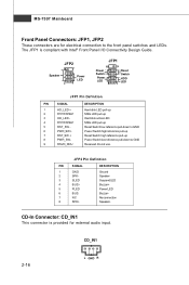
... Ground SpeakerSuspend LED Buzzer+ Power LED BuzzerNo connection Speaker+ CD-In Connector: CD_IN1 This connector is compliant with Intel® Front Panel I/O Connectivity Design Guide. MS-7507 Mainboard Front Panel Connectors: JFP1, JFP2 These connectors are for external audio input.
... Ground SpeakerSuspend LED Buzzer+ Power LED BuzzerNo connection Speaker+ CD-In Connector: CD_IN1 This connector is compliant with Intel® Front Panel I/O Connectivity Design Guide. MS-7507 Mainboard Front Panel Connectors: JFP1, JFP2 These connectors are for external audio input.
User Guide
Page 32
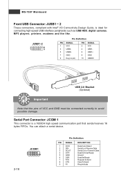
... Serial In or Receive Data Serial Out or Transmit Data Data Terminal Ready Ground Data Set Ready Request To Send Clear To Send Ring Indicate MS-7507 Mainboard Front USB Connector: JUSB1 ~ 2 These connectors, compliant with Intel® I/O Connectivity Design Guide, is a 16550A high speed communication port that the pins of VCC...
... Serial In or Receive Data Serial Out or Transmit Data Data Terminal Ready Ground Data Set Ready Request To Send Clear To Send Ring Indicate MS-7507 Mainboard Front USB Connector: JUSB1 ~ 2 These connectors, compliant with Intel® I/O Connectivity Design Guide, is a 16550A high speed communication port that the pins of VCC...
User Guide
Page 34
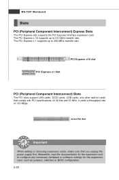
..., it yields a throughput rate of 133 MBps. 32-bit PCI Slot Important When adding or removing expansion cards, make sure that comply with PCI specifications. MS-7507 Mainboard Slots PCI (Peripheral Component Interconnect) Express Slots The PCI Express slot supports the PCI Express interface expansion card. PCI Express x16 slot PCI Express...
..., it yields a throughput rate of 133 MBps. 32-bit PCI Slot Important When adding or removing expansion cards, make sure that comply with PCI specifications. MS-7507 Mainboard Slots PCI (Peripheral Component Interconnect) Express Slots The PCI Express slot supports the PCI Express interface expansion card. PCI Express x16 slot PCI Express...
User Guide
Page 37
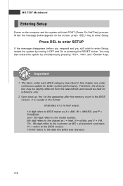
... under continuous update for reference only. 2. Therefore, the description may also restart the system by turning it OFF and On or pressing the RESET button. MS-7507 Mainboard Entering Setup Power on the screen, press key to enter Setup. V1.1 refers to the BIOS version. 101007 refers to the date this chapter... in this BIOS was released. 3-2 Press DEL to enter SETUP If the message disappears before you respond and you still wish to the customer as MS = all standard customers.
... under continuous update for reference only. 2. Therefore, the description may also restart the system by turning it OFF and On or pressing the RESET button. MS-7507 Mainboard Entering Setup Power on the screen, press key to enter Setup. V1.1 refers to the BIOS version. 101007 refers to the date this chapter... in this BIOS was released. 3-2 Press DEL to enter SETUP If the message disappears before you respond and you still wish to the customer as MS = all standard customers.
User Guide
Page 39
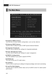
... Use this menu to specify your settings for frequency/voltage control and overclocking. Cell Menu Use this menu to specify your settings for integrated peripherals. MS-7507 Mainboard The Main Menu Standard CMOS Features Use this menu to specify your settings for power management. PNP/PCI Configurations This entry appears if your...
... Use this menu to specify your settings for frequency/voltage control and overclocking. Cell Menu Use this menu to specify your settings for integrated peripherals. MS-7507 Mainboard The Main Menu Standard CMOS Features Use this menu to specify your settings for power management. PNP/PCI Configurations This entry appears if your...
User Guide
Page 41
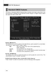
... the following screen appears. 3-6 Date (MM:DD:YY) This allows you to set the system time that you want (usually the current date). Read-only. MS-7507 Mainboard Standard CMOS Features The items in each item. year The year can be adjusted by numeric function keys.
... the following screen appears. 3-6 Date (MM:DD:YY) This allows you to set the system time that you want (usually the current date). Read-only. MS-7507 Mainboard Standard CMOS Features The items in each item. year The year can be adjusted by numeric function keys.
User Guide
Page 43
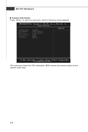
This sub-menu shows the CPU information, BIOS version and memory status of your system (read only). 3-8 MS-7507 Mainboard System Information Press to enter the sub-menu, and the following screen appears.
This sub-menu shows the CPU information, BIOS version and memory status of your system (read only). 3-8 MS-7507 Mainboard System Information Press to enter the sub-menu, and the following screen appears.
User Guide
Page 45
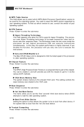
... end-user response times. Trusted Computing Press to enter the sub-menu: Hyper-Threading Technology This field appears only when the CPU supports Hyper-Threading. MS-7507 Mainboard MPS Table Version This field allows you to select which version to use only one core to execute the instructions. CPU Feature Press to...
... end-user response times. Trusted Computing Press to enter the sub-menu: Hyper-Threading Technology This field appears only when the CPU supports Hyper-Threading. MS-7507 Mainboard MPS Table Version This field allows you to select which version to use only one core to execute the instructions. CPU Feature Press to...
User Guide
Page 47
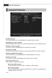
... to enable/disable the onboard USB controller. Audio Controller This setting is used PCI busmastering for reading/ writing to enable/disable the onboard IEEE1394 controller. MS-7507 Mainboard Integrated Peripherals USB Controller This setting allows you need to use a USB-interfaced device in the operating system. Onboard IEEE1394 Controller This item allows...
... to enable/disable the onboard USB controller. Audio Controller This setting is used PCI busmastering for reading/ writing to enable/disable the onboard IEEE1394 controller. MS-7507 Mainboard Integrated Peripherals USB Controller This setting allows you need to use a USB-interfaced device in the operating system. Onboard IEEE1394 Controller This item allows...
User Guide
Page 49
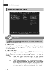
MS-7507 Mainboard Power Management Setup Important S3-related functions described in this section are : [S1] The S1 sleep mode is a low power state. ACPI Standby State ...
MS-7507 Mainboard Power Management Setup Important S3-related functions described in this section are : [S1] The S1 sleep mode is a low power state. ACPI Standby State ...


