User Guide
Page 8
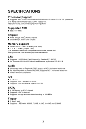
SPECIFICATIONS Processor Support l Supports Intel® Core2 Duo/ Pentium D/ Pentium 4/ Celeron D LGA 775 processors (For the latest information about CPU, please visit http://global.msi.com.tw/index.php?func=cpuform) Supported FSB l 800 / 533 MHz Chipset l North Bridge: Intel® 945GC chipset l South Bridge: ... DDR2 400/ 533/ 667 SDRAM (4GB Max) l 2 DDR2 DIMMs (240pin/ 1.8V) (For more information on compatible components, please visit http://global.msi.com.tw/index.php?func=testreport) LAN l Supports 10/100 Mb/s Fast Ethernet by Realtek RTL 8101E l Or Supports 10/100/1000 Mb/s Fast Ethermet...
SPECIFICATIONS Processor Support l Supports Intel® Core2 Duo/ Pentium D/ Pentium 4/ Celeron D LGA 775 processors (For the latest information about CPU, please visit http://global.msi.com.tw/index.php?func=cpuform) Supported FSB l 800 / 533 MHz Chipset l North Bridge: Intel® 945GC chipset l South Bridge: ... DDR2 400/ 533/ 667 SDRAM (4GB Max) l 2 DDR2 DIMMs (240pin/ 1.8V) (For more information on compatible components, please visit http://global.msi.com.tw/index.php?func=testreport) LAN l Supports 10/100 Mb/s Fast Ethernet by Realtek RTL 8101E l Or Supports 10/100/1000 Mb/s Fast Ethermet...
User Guide
Page 10
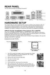
...Key boa rd Serial Port VGA Port USB Ports Mic SS-Out(optional) HARDWARE SETUP This chapter tells you how to install the CPU, memory modules, and expansion cards, as well as the mouse, keyboard, etc. Before you are matched. 4 Be sure to LGA 775...components and follow the installation procedures. Lift the load lever up and open the load plate. 6. CPU & Cooler Installation Procedures for LGA775 When you have installed the CPU, always cover it to install the CPU & cooler correctly. Introduction to grasp on connecting the peripheral devices, such as how to protect the...
...Key boa rd Serial Port VGA Port USB Ports Mic SS-Out(optional) HARDWARE SETUP This chapter tells you how to install the CPU, memory modules, and expansion cards, as well as the mouse, keyboard, etc. Before you are matched. 4 Be sure to LGA 775...components and follow the installation procedures. Lift the load lever up and open the load plate. 6. CPU & Cooler Installation Procedures for LGA775 When you have installed the CPU, always cover it to install the CPU & cooler correctly. Introduction to grasp on connecting the peripheral devices, such as how to protect the...
User Guide
Page 11
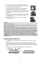
...the golden finger if the memory module is not installed, always protect your board running at maximum by overclocking and adjusting the CPU FSB frequency in BIOS. Installing Memory Modules 1. Mainboard photos shown in the DIMM slot. Insert the memory module vertically into the...t 5 According to the Intel North Bridge 945GC chipset spec, this overclocking behavior is over the mainboard to [Frequency/ Voltage Control]à[Adjust CPU FSB Frequency]. There you purchase. Press down the load lever lightly onto the load plate, and then secure the lever with the cooler. ...
...the golden finger if the memory module is not installed, always protect your board running at maximum by overclocking and adjusting the CPU FSB frequency in BIOS. Installing Memory Modules 1. Mainboard photos shown in the DIMM slot. Insert the memory module vertically into the...t 5 According to the Intel North Bridge 945GC chipset spec, this overclocking behavior is over the mainboard to [Frequency/ Voltage Control]à[Adjust CPU FSB Frequency]. There you purchase. Press down the load lever lightly onto the load plate, and then secure the lever with the cooler. ...
User Guide
Page 12
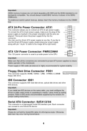
...GND PWR OK 5VSB +12V +12V +3.3V ATX 12V Power Connector: PWRCONN1 +12V +12V This 12V power connector is used to provide power to the CPU. If you to connect an ATX 24-pin power supply. GND GND Important: ...If you install two IDE devices on the same cable, you like to use the 20-pin ATX power supply as you must configure the drives to cable select mode or separately to IDE device... documentation supplied by setting jumpers. To connect the ATX 24-pin power supply, make sure the plug of the mainboard. You may occur during transmission...
...GND PWR OK 5VSB +12V +12V +3.3V ATX 12V Power Connector: PWRCONN1 +12V +12V This 12V power connector is used to provide power to the CPU. If you to connect an ATX 24-pin power supply. GND GND Important: ...If you install two IDE devices on the same cable, you like to use the 20-pin ATX power supply as you must configure the drives to cable select mode or separately to IDE device... documentation supplied by setting jumpers. To connect the ATX 24-pin power supply, make sure the plug of the mainboard. You may occur during transmission...
User Guide
Page 13
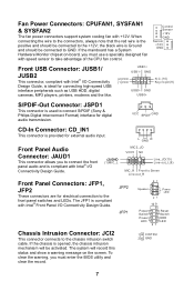
... the screen. L GND R Front Panel Audio Connector: JAUD1 This connector allows you must use a specially designed fan with speed sensor to take advantage of the CPU fan control. GND USB0+ S/PDIF-Out Connector: JSPD1 This connector is provided for external audio input. The system will be connected to GND. VCC SPDIF...
... the screen. L GND R Front Panel Audio Connector: JAUD1 This connector allows you must use a specially designed fan with speed sensor to take advantage of the CPU fan control. GND USB0+ S/PDIF-Out Connector: JSPD1 This connector is provided for external audio input. The system will be connected to GND. VCC SPDIF...
User Guide
Page 15
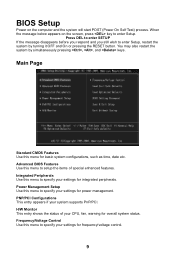
... system configurations, such as time, date etc. Advanced BIOS Features Use this menu for frequency/voltage control. 9 PNP/PCI Configurations This entry appears if your CPU, fan, warning for integrated peripherals. Main Page Standard CMOS Features Use this menu to specify your settings for overall system status. Power Management Setup Use...
... system configurations, such as time, date etc. Advanced BIOS Features Use this menu for frequency/voltage control. 9 PNP/PCI Configurations This entry appears if your CPU, fan, warning for integrated peripherals. Main Page Standard CMOS Features Use this menu to specify your settings for overall system status. Power Management Setup Use...
User Guide
Page 17
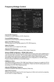
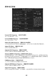
...on the SPD (Serial Presence Detect) EEPROM on the DRAM module. Please note that the setting options vary according to adjust the CPU ratio. Adjusted DDR Memory Frequency It shows the adjusted DDR Memory frequency. Adjust PCI Frequency This item allows you to run at ...different frequency combinations. Frequency/Voltage Control Current CPU Frequency It shows the current frequency of Memory. Read-only. Read-only. Read-only. Adjusted CPU Frequency It shows the adjusted CPU frequency (FSB x Ratio). Read-only. Current DRAM Frequency It shows the...
...on the SPD (Serial Presence Detect) EEPROM on the DRAM module. Please note that the setting options vary according to adjust the CPU ratio. Adjusted DDR Memory Frequency It shows the adjusted DDR Memory frequency. Adjust PCI Frequency This item allows you to run at ...different frequency combinations. Frequency/Voltage Control Current CPU Frequency It shows the current frequency of Memory. Read-only. Read-only. Read-only. Adjusted CPU Frequency It shows the adjusted CPU frequency (FSB x Ratio). Read-only. Current DRAM Frequency It shows the...

User Guide
Page 60
CPU CPU CPU 2 3 4 5 CPU 盖盘。 6. 在确定 CPU CPU CPU CPU 7. 目测 CPU 54 后置面板 Mouse Parallel Port LAN Li ne-In RS-Out(optional) Li ne-Out CS-Out(optional) Key boa rd Serial Port VGA Port USB Ports Mic SS-Out(optional) 硬件安装 CPU LGA775 CPU CPU CPU CPU CPU CPU CPU 安装 LGA 775 CPU LG775 CPU LG775 CPU 的表面. 1.
CPU CPU CPU 2 3 4 5 CPU 盖盘。 6. 在确定 CPU CPU CPU CPU 7. 目测 CPU 54 后置面板 Mouse Parallel Port LAN Li ne-In RS-Out(optional) Li ne-Out CS-Out(optional) Key boa rd Serial Port VGA Port USB Ports Mic SS-Out(optional) 硬件安装 CPU LGA775 CPU CPU CPU CPU CPU CPU CPU 安装 LGA 775 CPU LG775 CPU LG775 CPU 的表面. 1.

User Guide
Page 62
... GND GND Res +5V +5 V +5 V GND +3.3V +3.3V GND +5V GND +5V GND PWR OK 5VSB +12V +12V +3.3V ATX 12V PWRCONN1 此 12V CPU 供电。 +12V GND +12V GND 注意: ATX 350W FDD1 360KB, 720KB, 1.2MB, 1.44MB 或 2.88MB 软驱。 IDE 接口: IDE1 IDE IDE 设备...
... GND GND Res +5V +5 V +5 V GND +3.3V +3.3V GND +5V GND +5V GND PWR OK 5VSB +12V +12V +3.3V ATX 12V PWRCONN1 此 12V CPU 供电。 +12V GND +12V GND 注意: ATX 350W FDD1 360KB, 720KB, 1.2MB, 1.44MB 或 2.88MB 软驱。 IDE 接口: IDE1 IDE IDE 设备...
User Guide
Page 67
... DRAM Frequency (当前 DRAM Adjust CPU FSB Frequency (调整 CPU FSB CPU Disable CPU FSB 频率。 Adjust CPU Ratio (调整 CPU CPU 比率。 Adjusted CPU Frequency (调整 CPU CPU 频率(FSB x Ratio Advance DRAM Configuration > DRAM CAS# Latency CAS DRAM 2T 2.5T By SPD DRAM CAS#由...
... DRAM Frequency (当前 DRAM Adjust CPU FSB Frequency (调整 CPU FSB CPU Disable CPU FSB 频率。 Adjust CPU Ratio (调整 CPU CPU 比率。 Adjusted CPU Frequency (调整 CPU CPU 频率(FSB x Ratio Advance DRAM Configuration > DRAM CAS# Latency CAS DRAM 2T 2.5T By SPD DRAM CAS#由...

User Guide
Page 72
背板 Mouse Parallel Port LAN Li ne-In RS-Out(optional) Li ne-Out CS-Out(optional) Key boa rd Serial Port 硬體設定 VGA Port USB Ports USB Mic SS-Out(optional) 安裝 LGA775 LGA 775 LGA 775 CPU 針腳座 LGA 775 CPU 表面. Pin1 指示器 Pin1 指示器 1. CPU CPU CPU 2 3 4 5 6. 確認 CPU 66
背板 Mouse Parallel Port LAN Li ne-In RS-Out(optional) Li ne-Out CS-Out(optional) Key boa rd Serial Port 硬體設定 VGA Port USB Ports USB Mic SS-Out(optional) 安裝 LGA775 LGA 775 LGA 775 CPU 針腳座 LGA 775 CPU 表面. Pin1 指示器 Pin1 指示器 1. CPU CPU CPU 2 3 4 5 6. 確認 CPU 66

User Guide
Page 74
DDR2 DDR DDR DDR2 DDR2 DIMM1 ATX 24-Pin ATX1 ATX 24-pin ATX 24-pin ATX 20-pin ATX 20-pin pin 1 及 pin 13 pin 11、12、23 及 pin 24 ATX 12V PWRCONN1 12V CPU ATX 350 +3 . 3V -1 2V GND PS -ON # GND GND GND Res +5V +5 V +5 V GND +12V GND +3.3V +3.3V GND +5V GND +5V GND PWR OK 5VSB +12V +12V +3.3V +12V GND FDD1 360KB, 720KB, 1.2MB, 1.44MB 及 2.88MB IDE IDE1 IDE 裝置。 Jumper Serial ATA 連接器: SATA1/2/3/4 Serial ATA Serial ATA 裝置。 Serial ATA 90 68
DDR2 DDR DDR DDR2 DDR2 DIMM1 ATX 24-Pin ATX1 ATX 24-pin ATX 24-pin ATX 20-pin ATX 20-pin pin 1 及 pin 13 pin 11、12、23 及 pin 24 ATX 12V PWRCONN1 12V CPU ATX 350 +3 . 3V -1 2V GND PS -ON # GND GND GND Res +5V +5 V +5 V GND +12V GND +3.3V +3.3V GND +5V GND +5V GND PWR OK 5VSB +12V +12V +3.3V +12V GND FDD1 360KB, 720KB, 1.2MB, 1.44MB 及 2.88MB IDE IDE1 IDE 裝置。 Jumper Serial ATA 連接器: SATA1/2/3/4 Serial ATA Serial ATA 裝置。 Serial ATA 90 68
User Guide
Page 75
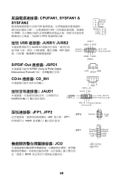
... Power LED 21 10 9 + -- + -+ JFP1 Power Reset Switch Switch Power HDD LED LED 21 JCI2 BIOS 1 CINTRU 2 GND 69 CPUFAN1, SYSFAN1 & SYSFAN2 12V 12V GND CPU Control Sensor +12V GND Sensor +12V GND 面板 USB 連接器: JUSB1/ JUSB2 Intel® I/O USB USB MP3 S/PDIF-Out 連接器...
... Power LED 21 10 9 + -- + -+ JFP1 Power Reset Switch Switch Power HDD LED LED 21 JCI2 BIOS 1 CINTRU 2 GND 69 CPUFAN1, SYSFAN1 & SYSFAN2 12V 12V GND CPU Control Sensor +12V GND Sensor +12V GND 面板 USB 連接器: JUSB1/ JUSB2 Intel® I/O USB USB MP3 S/PDIF-Out 連接器...

User Guide
Page 84
CPU 2. CPU す。 3. CPU 4 78 Mouse Parallel Port LAN Li ne-In RS-Out(optional) Li ne-Out CS-Out(optional) Key boa rd Serial Port VGA Port USB Ports Mic SS-Out(optional) LGA775CPU CPU CPU CPU CPU と CPU CPU LGA 775 CPU LGA 775 CPU の pin-pad 側 LGA 775 CPU の正面 1.
CPU 2. CPU す。 3. CPU 4 78 Mouse Parallel Port LAN Li ne-In RS-Out(optional) Li ne-Out CS-Out(optional) Key boa rd Serial Port VGA Port USB Ports Mic SS-Out(optional) LGA775CPU CPU CPU CPU CPU と CPU CPU LGA 775 CPU LGA 775 CPU の pin-pad 側 LGA 775 CPU の正面 1.

User Guide
Page 86
Notch Vo l t 注意: DDR2 DDR DDR DIMM1 ATX 24 ATX1 ATX電源 24 20 ピンの ATX 1/13 +3 . 3V -1 2V GND PS -ON # GND GND GND Res +5V +5 V +5 V GND +3.3V +3.3V GND +5V GND +5V GND PWR OK 5VSB +12V +12V +3.3V ATX 12V PWRCONN1 この 12V CPU +12V GND +12V GND 注意: ATX 350W FDD FDD1 360K, 720K, 1.2M, 1.44M 及び 2.88M IDE IDE1 IDE IDE 80
Notch Vo l t 注意: DDR2 DDR DDR DIMM1 ATX 24 ATX1 ATX電源 24 20 ピンの ATX 1/13 +3 . 3V -1 2V GND PS -ON # GND GND GND Res +5V +5 V +5 V GND +3.3V +3.3V GND +5V GND +5V GND PWR OK 5VSB +12V +12V +3.3V ATX 12V PWRCONN1 この 12V CPU +12V GND +12V GND 注意: ATX 350W FDD FDD1 360K, 720K, 1.2M, 1.44M 及び 2.88M IDE IDE1 IDE IDE 80
User Guide
Page 91
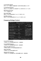
Load Fail-Safe Defaults BIOS Load Optimized Defaults BIOS BIOS Setting Password Save & Exit Setup CMOS Exit Without Saving CMOS Frequency/Voltage Control Current CPU Frequency CPU Current DRAM Frequency Adjust CPU FSB Frequency CPU FSB Adjust CPU Ratio CPU Adjusted CPU Frequency CPU FSB x 85
Load Fail-Safe Defaults BIOS Load Optimized Defaults BIOS BIOS Setting Password Save & Exit Setup CMOS Exit Without Saving CMOS Frequency/Voltage Control Current CPU Frequency CPU Current DRAM Frequency Adjust CPU FSB Frequency CPU FSB Adjust CPU Ratio CPU Adjusted CPU Frequency CPU FSB x 85

