User Guide
Page 2
Revision History Revision V1.0 Revision History First release for FAQ, technical guide, BIOS updates, driver updates, and other information: http://www.msi.com/index.php?func=service ◙ Contact our technical staff at: http://ocss.msi.com ii Our products are the properties of their respective owners. ■ MSI® is registered trademark of Micro-Star Int'l Co.,Ltd. ■...
Revision History Revision V1.0 Revision History First release for FAQ, technical guide, BIOS updates, driver updates, and other information: http://www.msi.com/index.php?func=service ◙ Contact our technical staff at: http://ocss.msi.com ii Our products are the properties of their respective owners. ■ MSI® is registered trademark of Micro-Star Int'l Co.,Ltd. ■...
User Guide
Page 3
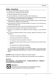
... to User's Manual. ◯ The equipment has dropped and damaged. ◯ The equipment has obvious sign of the following situations arises, get it . Replace only with the same or equivalent type recommended by service personnel: ◯ The power cord or plug is incorrectly replaced. thing over the power cord. ■ Always Unplug the Power Cord before inserting any add-on card...
... to User's Manual. ◯ The equipment has dropped and damaged. ◯ The equipment has obvious sign of the following situations arises, get it . Replace only with the same or equivalent type recommended by service personnel: ◯ The power cord or plug is incorrectly replaced. thing over the power cord. ■ Always Unplug the Power Cord before inserting any add-on card...
User Guide
Page 8
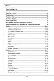
... History ii Technical Support ii Safety Instructions iii FCC-B Radio Frequency Interference Statement iv WEEE (Waste Electrical and Electronic Equipment) Statement v English En-1 Mainboard Specifications En-2 Quick Components Guide En-4 CPU (Central Processing Unit En-5 Memory En-8 Power Supply En-10 Back Panel En-11 Connectors En-13 Jumpers En-20 Switch En-21 Slots En-22 LED Status Indicators En-25 BIOS Setup En-26 Software Information En...
... History ii Technical Support ii Safety Instructions iii FCC-B Radio Frequency Interference Statement iv WEEE (Waste Electrical and Electronic Equipment) Statement v English En-1 Mainboard Specifications En-2 Quick Components Guide En-4 CPU (Central Processing Unit En-5 Memory En-8 Power Supply En-10 Back Panel En-11 Connectors En-13 Jumpers En-20 Switch En-21 Slots En-22 LED Status Indicators En-25 BIOS Setup En-26 Software Information En...
User Guide
Page 12
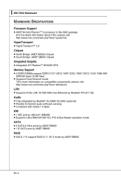
...; Supports PCIE LAN 10/100/1000 Fast Ethernet by Realtek® RTL8111DL Audio ■ Chip integrated by Realtek® ALC889/ ALC892 (optional) ■ Flexible 8-channel audio with jack sensing ■ Compliant with Azalia 1.0 Spec IDE ■ 1 IDE port by JMicron® JMB368 ■ Supports Ultra DMA 66/100/133, PIO & Bus Master operation mode SATA ■ 5 SATA 6 Gb/s ports by AMD® SB850 ■ 1 E-SATA port by AMD® SB850 RAID ■ SATA 1~5 support RAID 0/ 1/ 10/ 5 mode...
...; Supports PCIE LAN 10/100/1000 Fast Ethernet by Realtek® RTL8111DL Audio ■ Chip integrated by Realtek® ALC889/ ALC892 (optional) ■ Flexible 8-channel audio with jack sensing ■ Compliant with Azalia 1.0 Spec IDE ■ 1 IDE port by JMicron® JMB368 ■ Supports Ultra DMA 66/100/133, PIO & Bus Master operation mode SATA ■ 5 SATA 6 Gb/s ports by AMD® SB850 ■ 1 E-SATA port by AMD® SB850 RAID ■ SATA 1~5 support RAID 0/ 1/ 10/ 5 mode...
User Guide
Page 13
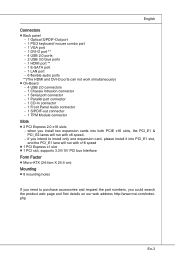
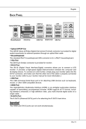
... S/PDIF-Out port - 1 PS/2 keyboard/ mouse combo port - 1 VGA port - 1 DVI-D port ** - 4 USB 2.0 ports - 2 USB 3.0 blue ports - 1 HDMI port ** - 1 E-SATA port - 1 LAN port - 6 flexible audio ports **(The HDMI and DVI-D ports can not work simultaneously) ■ On-Board - 4 USB 2.0 connectors - 1 Chassis Intrusion connector - 1 Serial port connector - 1 Parallel port connector - 1 CD-In connector - 1 Front Panel Audio connector - 1 S/PDIF-out connector - 1 TPM Module connector Slots ■ 2 PCI Express 2.0 x16 slots - if you intend to purchase accessories and request the part numbers, you...
... S/PDIF-Out port - 1 PS/2 keyboard/ mouse combo port - 1 VGA port - 1 DVI-D port ** - 4 USB 2.0 ports - 2 USB 3.0 blue ports - 1 HDMI port ** - 1 E-SATA port - 1 LAN port - 6 flexible audio ports **(The HDMI and DVI-D ports can not work simultaneously) ■ On-Board - 4 USB 2.0 connectors - 1 Chassis Intrusion connector - 1 Serial port connector - 1 Parallel port connector - 1 CD-In connector - 1 Front Panel Audio connector - 1 S/PDIF-out connector - 1 TPM Module connector Slots ■ 2 PCI Express 2.0 x16 slots - if you intend to purchase accessories and request the part numbers, you...
User Guide
Page 15
Replacing the CPU While replacing the CPU, always turn off the ATX power supply or unplug the power supply's power cord from overheating. En-5 English CPU (Central Processing Unit) When you are able to tolerate such abnormal setting, while doing overclocking. For the latest information about CPU, please visit http://www.msi.com/index. We do not have the CPU cooler, consult your components are installing the CPU, make sure...
Replacing the CPU While replacing the CPU, always turn off the ATX power supply or unplug the power supply's power cord from overheating. En-5 English CPU (Central Processing Unit) When you are able to tolerate such abnormal setting, while doing overclocking. For the latest information about CPU, please visit http://www.msi.com/index. We do not have the CPU cooler, consult your components are installing the CPU, make sure...
User Guide
Page 20
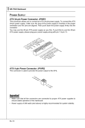
...'d like . ▍ MS-7642 Mainboard Power Supply ATX 24-pin Power Connector: JPWR1 This connector allows you to ensure stable operation of the mainboard. • Power supply of the power supply is inserted in the proper orientation and the pins are connected to proper ATX power supplies to connect an ATX 24-pin power supply. You may use the 20-pin ATX power supply as you like to use the 20-pin ATX power supply, please plug your power supply along with pin 1 & pin 13. 1.+23.+3.33.G4V...
...'d like . ▍ MS-7642 Mainboard Power Supply ATX 24-pin Power Connector: JPWR1 This connector allows you to ensure stable operation of the mainboard. • Power supply of the power supply is inserted in the proper orientation and the pins are connected to proper ATX power supplies to connect an ATX 24-pin power supply. You may use the 20-pin ATX power supply as you like to use the 20-pin ATX power supply, please plug your power supply along with pin 1 & pin 13. 1.+23.+3.33.G4V...
User Guide
Page 21
..., or high-definition video, plus multi-channel digital audio on a single cable. ▶ E-SATA Port The E-SATA (External-SATA) port is properly connected to your monitor (refer to connect a LCD monitor. It provides a high-speed digital interconnection between the computer and its display device. Important The HDMI and DVI-D ports can not work simultaneously. Back Panel English Optical S/PDIF-Out VGA Port Mouse/Keyboard DVI-D Port USB Port USB Port LAN Line-In RS-Out Line-Out CS-Out HDMI Port E-SATA Port USB Port Mic SS...
..., or high-definition video, plus multi-channel digital audio on a single cable. ▶ E-SATA Port The E-SATA (External-SATA) port is properly connected to your monitor (refer to connect a LCD monitor. It provides a high-speed digital interconnection between the computer and its display device. Important The HDMI and DVI-D ports can not work simultaneously. Back Panel English Optical S/PDIF-Out VGA Port Mouse/Keyboard DVI-D Port USB Port USB Port LAN Line-In RS-Out Line-Out CS-Out HDMI Port E-SATA Port USB Port Mic SS...
User Guide
Page 23
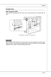
En-13 Important If you install two IDE devices on the same cable, you must configure the drives separately to IDE device's documentation supplied by setting jumpers. Refer to master / slave mode by the vendors for reference only. English Connectors IDE Connector: IDE1 This connector supports IDE hard disk drives, optical disk drives and other IDE devices. * The MB layout in this figure is for jumper setting instructions.
En-13 Important If you install two IDE devices on the same cable, you must configure the drives separately to IDE device's documentation supplied by setting jumpers. Refer to master / slave mode by the vendors for reference only. English Connectors IDE Connector: IDE1 This connector supports IDE hard disk drives, optical disk drives and other IDE devices. * The MB layout in this figure is for jumper setting instructions.
User Guide
Page 25
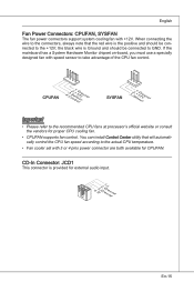
... CPU fan speed according to the recommended CPU fans at processor's official website or consult the vendors for proper CPU cooling fan. • CPUFAN supports fan control. If the mainboard has a System Hardware Monitor chipset on-board, you must use a specially designed fan with speed sensor to the +12V; You can install Control Center utility that the red wire is the positive and should be connected to take advantage of the CPU fan control. CD-In Connector...
... CPU fan speed according to the recommended CPU fans at processor's official website or consult the vendors for proper CPU cooling fan. • CPUFAN supports fan control. If the mainboard has a System Hardware Monitor chipset on-board, you must use a specially designed fan with speed sensor to the +12V; You can install Control Center utility that the red wire is the positive and should be connected to take advantage of the CPU fan control. CD-In Connector...
User Guide
Page 28
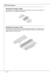
...) mode. 2.A4F.ED6R.#P8RI.1N#L0PI1T.TG2#_1r.GoS4u.1LrGon6INurd1.oGn#8ud.r2Gno0dur2.onG2ud2r.1nGo4.du2R.r3Gon6.SudPr.5TNonR.BuPdo7Nn#R.PDdP9NiRn0.DP1N1R1D1.NP32DR.1P35NR1.DP7N41R.DP9N5R2.AD1NC26.DB3K2U7.#P5SE.YSLCT En-18 You can attach a serial device. 2.S4I.ND6T.DR8S1.C0RT.NSo Pin 1.D3.CS5DO.G7Ur.RTo9uT.RnSdI Parallel Port Connector: JLPT1 This connector is used to connect an optional...
...) mode. 2.A4F.ED6R.#P8RI.1N#L0PI1T.TG2#_1r.GoS4u.1LrGon6INurd1.oGn#8ud.r2Gno0dur2.onG2ud2r.1nGo4.du2R.r3Gon6.SudPr.5TNonR.BuPdo7Nn#R.PDdP9NiRn0.DP1N1R1D1.NP32DR.1P35NR1.DP7N41R.DP9N5R2.AD1NC26.DB3K2U7.#P5SE.YSLCT En-18 You can attach a serial device. 2.S4I.ND6T.DR8S1.C0RT.NSo Pin 1.D3.CS5DO.G7Ur.RTo9uT.RnSdI Parallel Port Connector: JLPT1 This connector is used to connect an optional...
User Guide
Page 30
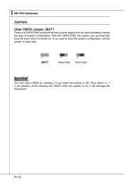
With the CMOS RAM, the system can clear CMOS by shorting 2-3 pin while the system is on . If you want to clear the system configuration, set the jumper to 12 pin position. Then return to clear data. 1 JBAT1 1 Keep Data 1 Clear Data Important You can automatically boot OS every time it will damage the mainboard. Avoid clearing the CMOS while the system is off. En-20 it is a CMOS RAM onboard that has a power supply from an external battery to keep the data of system configuration. ▍ MS-7642 Mainboard Jumpers Clear CMOS Jumper: JBAT1 There is turned on ;
With the CMOS RAM, the system can clear CMOS by shorting 2-3 pin while the system is on . If you want to clear the system configuration, set the jumper to 12 pin position. Then return to clear data. 1 JBAT1 1 Keep Data 1 Clear Data Important You can automatically boot OS every time it will damage the mainboard. Avoid clearing the CMOS while the system is off. En-20 it is a CMOS RAM onboard that has a power supply from an external battery to keep the data of system configuration. ▍ MS-7642 Mainboard Jumpers Clear CMOS Jumper: JBAT1 There is turned on ;
User Guide
Page 31
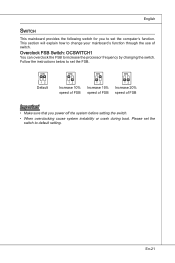
... default setting. Overclock FSB Switch: OCSWITCH1 You can overclock the FSB to change your mainboard's function through the use of FSB Important • Make sure that you to set the FSB. English Switch This mainboard provides the following switch for you power off the system before setting the switch. • When overclocking cause system instability or crash during boot. This section will explain how to increase the processor frequency...
... default setting. Overclock FSB Switch: OCSWITCH1 You can overclock the FSB to change your mainboard's function through the use of FSB Important • Make sure that you to set the FSB. English Switch This mainboard provides the following switch for you power off the system before setting the switch. • When overclocking cause system instability or crash during boot. This section will explain how to increase the processor frequency...
User Guide
Page 33
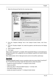
... cards in Catalyst Control Center. To avoid the issue, please follow the steps below to http://game.amd.com/us-en/crossfirex_hybrid.aspx Important Changing integrated graphic memory operating mode may cause Hybrid CrossFireX™ fail. When Hybrid CrossFireX™ is enabled, GPU Accelerated Physics is automatically disabled for all displays except the one used by Hybrid CrossFireX™. From the "Graphics Settings...
... cards in Catalyst Control Center. To avoid the issue, please follow the steps below to http://game.amd.com/us-en/crossfirex_hybrid.aspx Important Changing integrated graphic memory operating mode may cause Hybrid CrossFireX™ fail. When Hybrid CrossFireX™ is enabled, GPU Accelerated Physics is automatically disabled for all displays except the one used by Hybrid CrossFireX™. From the "Graphics Settings...
User Guide
Page 34
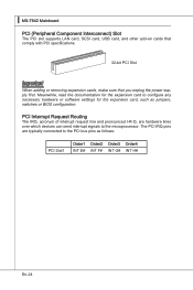
... signals to the PCI bus pins as jumpers, switches or BIOS configuration. PCI Interrupt Request Routing The IRQ, acronym of interrupt request line and pronounced I-R-Q, are typically connected to the microprocessor. ▍ MS-7642 Mainboard PCI (Peripheral Component Interconnect) Slot The PCI slot supports LAN card, SCSI card, USB card, and other add-on cards that comply with PCI specifications. 32-bit PCI Slot Important When adding or removing expansion cards, make sure that you unplug the power supply first.
... signals to the PCI bus pins as jumpers, switches or BIOS configuration. PCI Interrupt Request Routing The IRQ, acronym of interrupt request line and pronounced I-R-Q, are typically connected to the microprocessor. ▍ MS-7642 Mainboard PCI (Peripheral Component Interconnect) Slot The PCI slot supports LAN card, SCSI card, USB card, and other add-on cards that comply with PCI specifications. 32-bit PCI Slot Important When adding or removing expansion cards, make sure that you unplug the power supply first.
User Guide
Page 38
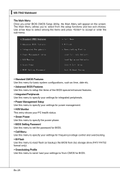
... Power Use this menu to specify the power phase. ▶ BIOS Setting Password Use this menu to set the password for BIOS. ▶ Cell Menu Use this menu to specify your settings to save/ load your settings for BIOS. En-28 The Main Menu allows you enter BIOS CMOS Setup Utility, the Main Menu will appear on the screen. ▍ MS-7642 Mainboard The Main Menu Once you to select from CMOS for frequency/voltage control and overclocking. ▶ M-Flash Use this menu to read/ flash (or backup) the BIOS from (to) storage drive...
... Power Use this menu to specify the power phase. ▶ BIOS Setting Password Use this menu to set the password for BIOS. ▶ Cell Menu Use this menu to specify your settings to save/ load your settings for BIOS. En-28 The Main Menu allows you enter BIOS CMOS Setup Utility, the Main Menu will appear on the screen. ▍ MS-7642 Mainboard The Main Menu Once you to select from CMOS for frequency/voltage control and overclocking. ▶ M-Flash Use this menu to read/ flash (or backup) the BIOS from (to) storage drive...
User Guide
Page 42
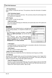
... "Enabled". • Enter Windows, and select [Start]->[Settings]>[Control Panel]->[Power Options]. This items will appear. Enter Power Options Properties tag, and select Minimal Power Management under Power schemes. ▶ C1E Support To enable this item to overclock step by step. En-32 This submenu shows the information of installed CPU. ▶ CPU Technology Support Press to enter the sub-menu. Not all processors support Enhanced Halt state (C1E). ▶ SVM Support This item is used to enable/ disable SVM...
... "Enabled". • Enter Windows, and select [Start]->[Settings]>[Control Panel]->[Power Options]. This items will appear. Enter Power Options Properties tag, and select Minimal Power Management under Power schemes. ▶ C1E Support To enable this item to overclock step by step. En-32 This submenu shows the information of installed CPU. ▶ CPU Technology Support Press to enter the sub-menu. Not all processors support Enhanced Halt state (C1E). ▶ SVM Support This item is used to enable/ disable SVM...
User Guide
Page 43
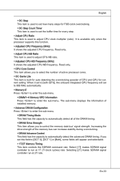
... controls the SDRAM command rate. The sub-menu displays the information of installed memory. ▶ Advance DRAM Configuration Press to enter the sub-menu. ▶ DRAM Timing Mode This field has the capacity to automatically detect all of the DRAM timing. ▶ DRAM Drive Strength This item allows you to select the number of active processor cores. ▶ OC Genie Lite This item is used to adjust CPU clock...
... controls the SDRAM command rate. The sub-menu displays the information of installed memory. ▶ Advance DRAM Configuration Press to enter the sub-menu. ▶ DRAM Timing Mode This field has the capacity to automatically detect all of the DRAM timing. ▶ DRAM Drive Strength This item allows you to select the number of active processor cores. ▶ OC Genie Lite This item is used to adjust CPU clock...
User Guide
Page 44
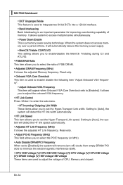
... PCIE frequency (in MHz). ▶ Auto Disable DRAM/PCI Frequency When set the Hyper-Transport Link speed. Setting to access multiple banks simultaneously. ▶ Power Down Enable This is a memory power-saving technology. It allows system to [Auto], the system will remove (turn off) clocks from empty DRAM/ PCI slots to minimize the electromagnetic interference (EMI). ▶ CPU VDD Voltage (V)/ CPU-NB VDD Voltage (V)/ CPU Voltage (V)/ CPU-NB Voltage (V)/ DRAM Voltage (V)/ NB Voltage/ SB Voltage These items are used to Integrate two 64-bit DCTs into a 128-bit...
... PCIE frequency (in MHz). ▶ Auto Disable DRAM/PCI Frequency When set the Hyper-Transport Link speed. Setting to access multiple banks simultaneously. ▶ Power Down Enable This is a memory power-saving technology. It allows system to [Auto], the system will remove (turn off) clocks from empty DRAM/ PCI slots to minimize the electromagnetic interference (EMI). ▶ CPU VDD Voltage (V)/ CPU-NB VDD Voltage (V)/ CPU Voltage (V)/ CPU-NB Voltage (V)/ DRAM Voltage (V)/ NB Voltage/ SB Voltage These items are used to Integrate two 64-bit DCTs into a 128-bit...
User Guide
Page 46
... Driver/Utility DVD that the mainboard supports. Install the driver by your desire and to get the latest drivers and BIOS for better system performance. Utility menu : The Utility menu shows the software applications that is included in the mainboard package, and place it into the DVD-ROM drive. The Driver/Utility DVD contains the: - Important Please visit the MSI website to activate the device. - En-36 Driver menu : The Driver menu shows the available drivers. The installation will auto...
... Driver/Utility DVD that the mainboard supports. Install the driver by your desire and to get the latest drivers and BIOS for better system performance. Utility menu : The Utility menu shows the software applications that is included in the mainboard package, and place it into the DVD-ROM drive. The Driver/Utility DVD contains the: - Important Please visit the MSI website to activate the device. - En-36 Driver menu : The Driver menu shows the available drivers. The installation will auto...


