
User Guide
Page 2
... Support If a problem arises with your system and no guarantee is given as to make changes without notice. Preface Copyright Notice The material in the preparation of this document is the intellectual property of MICRO-STAR INTERNATIONAL. Revision History Revision V3.0 V3.1 Revision History First release for FAQ, technical guide, BIOS updates, driver updates, and other information: http://www.msi...
... Support If a problem arises with your system and no guarantee is given as to make changes without notice. Preface Copyright Notice The material in the preparation of this document is the intellectual property of MICRO-STAR INTERNATIONAL. Revision History Revision V3.0 V3.1 Revision History First release for FAQ, technical guide, BIOS updates, driver updates, and other information: http://www.msi...
User Guide
Page 8
...Started 1-1 Mainboard Specifications 1-2 Mainboard Layout 1-4 Packing Checklist 1-5 Chapter 2 Hardware Setup 2-1 Quick Components Guide 2-2 Screw Holes 2-3 CPU (Central Processing Unit 2-4 Memory 2-7 Power Supply 2-9 Back Panel 2-10 Connectors 2-12 Jumpers 2-17 Slots 2-18 LED Status Indicators 2-19 Chapter 3 BIOS Setup 3-1 Entering Setup 3-2 The Main Menu 3-4 Standard CMOS Features 3-6 Advanced BIOS Features 3-8 Integrated Peripherals 3-10 Power Management Setup 3-12 H/W Monitor 3-14 Green Power 3-15 BIOS Setting Password 3-16 Cell Menu 3-18 M-Flash 3-24 Overclocking...
...Started 1-1 Mainboard Specifications 1-2 Mainboard Layout 1-4 Packing Checklist 1-5 Chapter 2 Hardware Setup 2-1 Quick Components Guide 2-2 Screw Holes 2-3 CPU (Central Processing Unit 2-4 Memory 2-7 Power Supply 2-9 Back Panel 2-10 Connectors 2-12 Jumpers 2-17 Slots 2-18 LED Status Indicators 2-19 Chapter 3 BIOS Setup 3-1 Entering Setup 3-2 The Main Menu 3-4 Standard CMOS Features 3-6 Advanced BIOS Features 3-8 Integrated Peripherals 3-10 Power Management Setup 3-12 H/W Monitor 3-14 Green Power 3-15 BIOS Setting Password 3-16 Cell Menu 3-18 M-Flash 3-24 Overclocking...
User Guide
Page 12
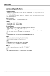
....msi.com/index.php?func=testreport) LAN ■ Supports PCIE Gb LAN (10/100/1000) by Realtek® RTL8111E Audio ■ HD audio codec integrated by Realtek® ALC892 ■ Flexible 8-channel audio with jack sensing SATA ■ 6 SATA 6Gb/s ports (SATA1~6) by AMD® SB850 ■ Supports hot plug & asynchronous notification USB 3.0 ■ 2 USB 3.0 ports (back panel) by NEC uPD720200F1 RAID ■ SATA1~6 support RAID 0/ 1/ 5/ 10 mode by AMD® SB850 1-2 Getting Started Mainboard Specifications Processor Support ■ AMD...
....msi.com/index.php?func=testreport) LAN ■ Supports PCIE Gb LAN (10/100/1000) by Realtek® RTL8111E Audio ■ HD audio codec integrated by Realtek® ALC892 ■ Flexible 8-channel audio with jack sensing SATA ■ 6 SATA 6Gb/s ports (SATA1~6) by AMD® SB850 ■ Supports hot plug & asynchronous notification USB 3.0 ■ 2 USB 3.0 ports (back panel) by NEC uPD720200F1 RAID ■ SATA1~6 support RAID 0/ 1/ 5/ 10 mode by AMD® SB850 1-2 Getting Started Mainboard Specifications Processor Support ■ AMD...

User Guide
Page 26
... speakers through an optical fiber cable. ▶ USB 2.0 Port The USB (Universal Serial Bus) port is for a PS/2® mouse/keyboard. ▶ Clear CMOS Button There is turned on board that you want to clear the system configuration, use the button to keep the system configuration data. With the CMOS RAM, the system can automatically boot OS every time it is a CMOS RAM on . Important • Make sure that has a power supply from external battery to clear data. Supports...
... speakers through an optical fiber cable. ▶ USB 2.0 Port The USB (Universal Serial Bus) port is for a PS/2® mouse/keyboard. ▶ Clear CMOS Button There is turned on board that you want to clear the system configuration, use the button to keep the system configuration data. With the CMOS RAM, the system can automatically boot OS every time it is a CMOS RAM on . Important • Make sure that has a power supply from external battery to clear data. Supports...

User Guide
Page 31
... 1.V3C.U5CS.U7BS.0G9B-.rN0o+ounPdin * The MB layout in this figure is provided for reference only. USB 2.0 Bracket (optional) Serial Port Connector: JCOM1 This connector is ideal for connecting high-speed USB interface peripherals such as USB HDD, digital cameras, MP3 players, printers, modems and the like. You can attach a serial device. 2.S4I.ND6T.DR8S1.C0RT.NSo Pin 1.D3.CS5DO.G7Ur.RTo9uT.RnSdI CD-In...
... 1.V3C.U5CS.U7BS.0G9B-.rN0o+ounPdin * The MB layout in this figure is provided for reference only. USB 2.0 Bracket (optional) Serial Port Connector: JCOM1 This connector is ideal for connecting high-speed USB interface peripherals such as USB HDD, digital cameras, MP3 players, printers, modems and the like. You can attach a serial device. 2.S4I.ND6T.DR8S1.C0RT.NSo Pin 1.D3.CS5DO.G7Ur.RTo9uT.RnSdI CD-In...

User Guide
Page 33
With the CMOS RAM, the system can clear CMOS by shorting 2-3 pin while the system is a CMOS RAM onboard that has a power supply from an external battery to 1-2 pin position. Avoid clearing the CMOS while the system is turned on ; If you want to clear the system configuration, set the jumper to clear data. 1 JBAT1 1 Keep Data 1 Clear Data Important You can automatically boot OS every time it will damage the mainboard. 2-17 Then return to keep the data of system configuration. it is on . Chapter 2 MS-7640 Jumpers Clear CMOS Jumper: JBAT1 There is off.
With the CMOS RAM, the system can clear CMOS by shorting 2-3 pin while the system is a CMOS RAM onboard that has a power supply from an external battery to 1-2 pin position. Avoid clearing the CMOS while the system is turned on ; If you want to clear the system configuration, set the jumper to clear data. 1 JBAT1 1 Keep Data 1 Clear Data Important You can automatically boot OS every time it will damage the mainboard. 2-17 Then return to keep the data of system configuration. it is on . Chapter 2 MS-7640 Jumpers Clear CMOS Jumper: JBAT1 There is off.
User Guide
Page 34
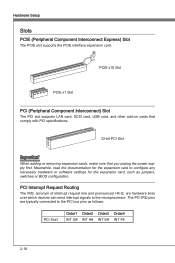
... I-R-Q, are typically connected to the PCI bus pins as jumpers, switches or BIOS configuration. The PCI IRQ pins are hardware lines over which devices can send interrupt signals to configure any necessary hardware or software settings for the expansion card to the microprocessor. PCIE x16 Slot PCIE x1 Slot PCI (Peripheral Component Interconnect) Slot The PCI slot supports LAN card, SCSI card, USB card, and other add-on cards that comply with PCI specifications. 32-bit PCI Slot Important When adding or removing expansion cards, make sure...
... I-R-Q, are typically connected to the PCI bus pins as jumpers, switches or BIOS configuration. The PCI IRQ pins are hardware lines over which devices can send interrupt signals to configure any necessary hardware or software settings for the expansion card to the microprocessor. PCIE x16 Slot PCIE x1 Slot PCI (Peripheral Component Interconnect) Slot The PCI slot supports LAN card, SCSI card, USB card, and other add-on cards that comply with PCI specifications. 32-bit PCI Slot Important When adding or removing expansion cards, make sure...
User Guide
Page 44
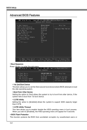
... option to [Enabled] allows the system to support HDD capacity larger than 2.2TB. ▶ 2.2TB Infinity Timeout This item allows you set the first/ second boot device where BIOS attempts to load the disk operating system. ▶ Boot From Other Device Setting the option to [Yes] allows the system to try to boot from other device, if the system fails to boot from accidental corruption by unauthorized users...
... option to [Enabled] allows the system to support HDD capacity larger than 2.2TB. ▶ 2.2TB Infinity Timeout This item allows you set the first/ second boot device where BIOS attempts to load the disk operating system. ▶ Boot From Other Device Setting the option to [Yes] allows the system to try to boot from other device, if the system fails to boot from accidental corruption by unauthorized users...

User Guide
Page 45
... it via the various ACPI methods. ▶ TCG/TPM Support Setting the option to update the BIOS. Setting to select the MPS version supported by your primary graphics adapter. ▶ PCI Latency Timer This item controls how long each PCI device can to enable it, and will need to [On] will turn on the boot-up screen. For better PCI performance, you with a Flash utility. You can hold the bus before another takes...
... it via the various ACPI methods. ▶ TCG/TPM Support Setting the option to update the BIOS. Setting to select the MPS version supported by your primary graphics adapter. ▶ PCI Latency Timer This item controls how long each PCI device can to enable it, and will need to [On] will turn on the boot-up screen. For better PCI performance, you with a Flash utility. You can hold the bus before another takes...
User Guide
Page 46
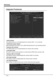
...; USB Device Legacy Support Select [Enabled] if you need to use a USB-interfaced device in the operating system. ▶ Onboard LAN Controller This setting allows you to enable/disable the onboard LAN controller. ▶ LAN Option ROM This item is used to decide whether to invoke the Boot ROM of the onboard LAN. ▶ Onboard USB 3.0 Controller This setting is used to enable/disable the onboard USB 3.0 controller. ▶ HD Audio Controller This setting is used to enable/disable the onboard audio controller. ▶ On-Chip ATA Devices Press to enter the sub-menu and the following screen...
...; USB Device Legacy Support Select [Enabled] if you need to use a USB-interfaced device in the operating system. ▶ Onboard LAN Controller This setting allows you to enable/disable the onboard LAN controller. ▶ LAN Option ROM This item is used to decide whether to invoke the Boot ROM of the onboard LAN. ▶ Onboard USB 3.0 Controller This setting is used to enable/disable the onboard USB 3.0 controller. ▶ HD Audio Controller This setting is used to enable/disable the onboard audio controller. ▶ On-Chip ATA Devices Press to enter the sub-menu and the following screen...

User Guide
Page 47
Chapter 3 MS-7640 ▶ PCI IDE BusMaster This item allows you to enable/ disable BIOS to used PCI busmastering for reading/ writing to IDE drives. ▶ On-Chip SATA Controller This item allows users to enable or disable the SATA controller. ▶ RAID Mode This item is used to select operation mode for SATA connectors. ▶ I/O Devices Press to enter the sub-menu and the following screen appears: ▶ COM Port 1 Select an address and corresponding interrupt for the serial port. 3-11
Chapter 3 MS-7640 ▶ PCI IDE BusMaster This item allows you to enable/ disable BIOS to used PCI busmastering for reading/ writing to IDE drives. ▶ On-Chip SATA Controller This item allows users to enable or disable the SATA controller. ▶ RAID Mode This item is used to select operation mode for SATA connectors. ▶ I/O Devices Press to enter the sub-menu and the following screen appears: ▶ COM Port 1 Select an address and corresponding interrupt for the serial port. 3-11

User Guide
Page 49
... set the wake up the system on PCIE or PCI device. ▶ Resume By RTC Alarm The field is used to RAM) sleep state. ▶ Resume S3/S5 By PS/2 Keyboa / Mouse These items determine whether the system will be awakened from what power saving modes when input signal of booting up events. Chapter 3 ▶ Wake Up Event Setup Press to enter the sub-menu...
... set the wake up the system on PCIE or PCI device. ▶ Resume By RTC Alarm The field is used to RAM) sleep state. ▶ Resume S3/S5 By PS/2 Keyboa / Mouse These items determine whether the system will be awakened from what power saving modes when input signal of booting up events. Chapter 3 ▶ Wake Up Event Setup Press to enter the sub-menu...

User Guide
Page 50
... message if the chassis is used to select the type of installed CPU FAN. ▶ CPU Smart Fan Target The mainboard provides the Smart Fan function which can enable a fan target value here. To clear the warning message, set the field to keep it with in a specific range. The setting of the monitored hardware devices/components such as CPU voltage, temperatures and all fans' speeds. 3-14 You can control the CPU fan speed automatically depending on the current temperature to [Reset].
... message if the chassis is used to select the type of installed CPU FAN. ▶ CPU Smart Fan Target The mainboard provides the Smart Fan function which can enable a fan target value here. To clear the warning message, set the field to keep it with in a specific range. The setting of the monitored hardware devices/components such as CPU voltage, temperatures and all fans' speeds. 3-14 You can control the CPU fan speed automatically depending on the current temperature to [Reset].

User Guide
Page 53
... have the right to change the settings of BIOS password protection that is used to confirm the password. Retype the password and press . Chapter 3 MS-7640 Important Type the password, up confirming the password will boot and you can enter Setup without entering any part of the setup menu. ▶ User Access Level This item is used to assign a place to save the supervisor password. 3-17 To clear a set , you will be prompted...
... have the right to change the settings of BIOS password protection that is used to confirm the password. Retype the password and press . Chapter 3 MS-7640 Important Type the password, up confirming the password will boot and you can enter Setup without entering any part of the setup menu. ▶ User Access Level This item is used to assign a place to save the supervisor password. 3-17 To clear a set , you will be prompted...

User Guide
Page 59
... flatter curves. Setting to [Auto], the system will remove (turn off) clocks from empty DRAM/ PCI slots to minimize the electromagnetic interference (EMI). ▶ CPU VDD Voltage (V)/ CPU-NB VDD Voltage (V)/ DRAM Voltage (V)/ NB Voltage (V) These items are reduced to select the PCIE frequency (in clock speed which may just cause your local EMI regulation. • Remember to adjust the voltage of CPU, Memory and chipset. ▶ Spread Spectrum When the mainboard's clock generator pulses...
... flatter curves. Setting to [Auto], the system will remove (turn off) clocks from empty DRAM/ PCI slots to minimize the electromagnetic interference (EMI). ▶ CPU VDD Voltage (V)/ CPU-NB VDD Voltage (V)/ DRAM Voltage (V)/ NB Voltage (V) These items are reduced to select the PCIE frequency (in clock speed which may just cause your local EMI regulation. • Remember to adjust the voltage of CPU, Memory and chipset. ▶ Spread Spectrum When the mainboard's clock generator pulses...

User Guide
Page 62
Note: we suggest you using [ROM] as default name. ▶ Start to Save File Press "Enter" and select "OK" the system will stare to save it only supports FAT/ FAT32 file system drive. ▶ Save File Name as Please setup a specific name for the BIOS file, which will be saved into the USB drive/ storage drive. Note: it to USB drive/ storage drive. ▶ Save File to Selected Device Please setup a specific folder in specific USB drive/ storage drive to [Boot] ], this item...
Note: we suggest you using [ROM] as default name. ▶ Start to Save File Press "Enter" and select "OK" the system will stare to save it only supports FAT/ FAT32 file system drive. ▶ Save File Name as Please setup a specific name for the BIOS file, which will be saved into the USB drive/ storage drive. Note: it to USB drive/ storage drive. ▶ Save File to Selected Device Please setup a specific folder in specific USB drive/ storage drive to [Boot] ], this item...

User Guide
Page 66
... software utility and shall be held for reference only. The setup screen will automati- Click Finish to enhance audio applications. Select Realtek HD Audio Drivers to install the Realtek High Definition Audio Driver. 6. Realtek Audio Installing the Realtek HD Audio Driver You need to install the HD audio driver for Realtek audio codec to function properly before installing the driver. Insert the application DVD into the DVD-ROM drive. Click Next to start installing the drivers. 5. cally appear. 2. channel...
... software utility and shall be held for reference only. The setup screen will automati- Click Finish to enhance audio applications. Select Realtek HD Audio Drivers to install the Realtek High Definition Audio Driver. 6. Realtek Audio Installing the Realtek HD Audio Driver You need to install the HD audio driver for Realtek audio codec to function properly before installing the driver. Insert the application DVD into the DVD-ROM drive. Click Next to start installing the drivers. 5. cally appear. 2. channel...

User Guide
Page 67
Software panel overview The following figure describes the function of the screen). Device Selection Application Enhancement Volume Adjustment Jack status panel A-3 You may double click the icon and the GUI will appear at the notification area (lower right of the Realtek HD Audio Manager panel. double click the icon It is also available to enable the audio driver by clicking the Realtek HD Audio Manager from the Control Panel. Appendix A MS-7640 Software Configuration After installing the audio driver, the "Realtek HD Audio Manager" icon will pop up accordingly.
Software panel overview The following figure describes the function of the screen). Device Selection Application Enhancement Volume Adjustment Jack status panel A-3 You may double click the icon and the GUI will appear at the notification area (lower right of the Realtek HD Audio Manager panel. double click the icon It is also available to enable the audio driver by clicking the Realtek HD Audio Manager from the Control Panel. Appendix A MS-7640 Software Configuration After installing the audio driver, the "Realtek HD Audio Manager" icon will pop up accordingly.
User Guide
Page 78
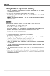
... (floppy/ CD/ DVD or USB) Important Please follow the instruction below to make a SATA RAID driver for the Windows Setup screen to copy the files from the Windows CD, and the Windows Setup program starts. 2. Note: for Windows Vista/ Windows 7, you have successfully installed the RAID driver, and Windows setup should be shown a list of available RAID controller(s). 6. AMD RAID Installing the RAID Driver (for 32-bit/ 64-bit version system and then press ENTER. 7. The next screen should confirm that contains the RAID driver, press the "S" key...
... (floppy/ CD/ DVD or USB) Important Please follow the instruction below to make a SATA RAID driver for the Windows Setup screen to copy the files from the Windows CD, and the Windows Setup program starts. 2. Note: for Windows Vista/ Windows 7, you have successfully installed the RAID driver, and Windows setup should be shown a list of available RAID controller(s). 6. AMD RAID Installing the RAID Driver (for 32-bit/ 64-bit version system and then press ENTER. 7. The next screen should confirm that contains the RAID driver, press the "S" key...

User Guide
Page 79
The DVD will auto-run and the setup screen will be automatically installed. B-9 The AMD chipset drivers includes RAID Driver. 4. Under the Driver tab, click on AMD chipset drivers by your need. The driver will appear. 3. Appendix B MS-7640 Installing the RAID Driver Under Windows (for Non-bootable RAID Array) 1. Insert the MSI DVD into the DVD-ROM drive. 2.
The DVD will auto-run and the setup screen will be automatically installed. B-9 The AMD chipset drivers includes RAID Driver. 4. Under the Driver tab, click on AMD chipset drivers by your need. The driver will appear. 3. Appendix B MS-7640 Installing the RAID Driver Under Windows (for Non-bootable RAID Array) 1. Insert the MSI DVD into the DVD-ROM drive. 2.


