User Guide
Page 2
... FAQ, technical guide, BIOS updates, driver updates, and other information: http://www.msi.com/index.php?func=service ◙ Contact our technical staff at: http://ocss.msi.com ii We take every care in this document, but no solution can be obtained from the user's manual, please contact your system and no guarantee is given as to make changes without notice...
... FAQ, technical guide, BIOS updates, driver updates, and other information: http://www.msi.com/index.php?func=service ◙ Contact our technical staff at: http://ocss.msi.com ii We take every care in this document, but no solution can be obtained from the user's manual, please contact your system and no guarantee is given as to make changes without notice...
User Guide
Page 8
... Started 1-1 Mainboard Specifications 1-2 Mainboard Layout 1-4 Packing Checklist 1-5 Chapter 2 Hardware Setup 2-1 Quick Components Guide 2-2 CPU (Central Processing Unit 2-3 Memory 2-6 Power Supply 2-8 Back Panel 2-9 Connectors 2-11 Jumpers 2-17 Switch 2-18 Button(optional 2-19 Slots 2-20 LED Status Indicators 2-23 Chapter 3 BIOS Setup 3-1 Entering Setup 3-2 The Main Menu 3-4 Standard CMOS Features 3-6 Advanced BIOS Features 3-9 Integrated Peripherals 3-11 Power Management Setup 3-13 H/W Monitor 3-15 Green Power 3-16 BIOS Setting Password 3-17 Cell Menu 3-18 M-Flash...
... Started 1-1 Mainboard Specifications 1-2 Mainboard Layout 1-4 Packing Checklist 1-5 Chapter 2 Hardware Setup 2-1 Quick Components Guide 2-2 CPU (Central Processing Unit 2-3 Memory 2-6 Power Supply 2-8 Back Panel 2-9 Connectors 2-11 Jumpers 2-17 Switch 2-18 Button(optional 2-19 Slots 2-20 LED Status Indicators 2-23 Chapter 3 BIOS Setup 3-1 Entering Setup 3-2 The Main Menu 3-4 Standard CMOS Features 3-6 Advanced BIOS Features 3-9 Integrated Peripherals 3-11 Power Management Setup 3-13 H/W Monitor 3-15 Green Power 3-16 BIOS Setting Password 3-17 Cell Menu 3-18 M-Flash...
User Guide
Page 11
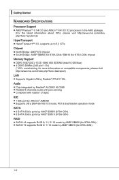
... on compatible components, please visit http://www.msi.com/index.php?func=testreport) LAN ■ Supports Gigabit LAN by Realtek® RTL8111DL Audio ■ Chip integrated by Realtek® ALC892/ ALC889 ■ Flexible 8-channels audio with jack sensing ■ Compliant with Azalia 1.0 Spec IDE ■ 1 IDE port by JMicron® JMB368 ■ Supports Ultra DMA 66/100/133 mode, PIO & Bus Master operation mode SATA ■ 6 SATA 6Gb/s ports by AMD...
... on compatible components, please visit http://www.msi.com/index.php?func=testreport) LAN ■ Supports Gigabit LAN by Realtek® RTL8111DL Audio ■ Chip integrated by Realtek® ALC892/ ALC889 ■ Flexible 8-channels audio with jack sensing ■ Compliant with Azalia 1.0 Spec IDE ■ 1 IDE port by JMicron® JMB368 ■ Supports Ultra DMA 66/100/133 mode, PIO & Bus Master operation mode SATA ■ 6 SATA 6Gb/s ports by AMD...
User Guide
Page 26
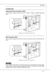
... This connector supports IDE hard disk drives, optical disk drives and other IDE devices. * The MB layout in this figure is for reference only. Important If you install two IDE devices on the same cable, you must configure the drives separately to IDE device's documentation supplied by setting jumpers. Refer to master / slave mode by the vendors for jumper setting instructions. 2-11 MS-7599 Connectors Floppy Disk Drive Connector: FDD1 This connector supports 360 KB, 720 KB, 1.2 MB, 1.44 MB or 2.88 MB floppy disk drive...
... This connector supports IDE hard disk drives, optical disk drives and other IDE devices. * The MB layout in this figure is for reference only. Important If you install two IDE devices on the same cable, you must configure the drives separately to IDE device's documentation supplied by setting jumpers. Refer to master / slave mode by the vendors for jumper setting instructions. 2-11 MS-7599 Connectors Floppy Disk Drive Connector: FDD1 This connector supports 360 KB, 720 KB, 1.2 MB, 1.44 MB or 2.88 MB floppy disk drive...
User Guide
Page 28
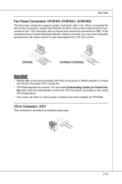
... of the CPU fan control. If the mainboard has a System Hardware Monitor chipset on-board, you must use a specially designed fan with 3 or 4 pins power connector are both available for CPUFAN. When connecting the wire to the connectors, always note that will automatically control the CPU fan speed according to the actual CPU temperature. • Fan cooler set with speed sensor to the +12V; You can install Overclocking Center (or Control Center) utility that the red wire is Ground...
... of the CPU fan control. If the mainboard has a System Hardware Monitor chipset on-board, you must use a specially designed fan with 3 or 4 pins power connector are both available for CPUFAN. When connecting the wire to the connectors, always note that will automatically control the CPU fan speed according to the actual CPU temperature. • Fan cooler set with speed sensor to the +12V; You can install Overclocking Center (or Control Center) utility that the red wire is Ground...
User Guide
Page 32
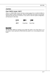
If you want to clear the system configuration, set the jumper to clear data. 1 JBAT1 1 Keep Data 1 Clear Data Important You can automatically boot OS every time it will damage the mainboard. 2-17 MS-7599 Jumpers Clear CMOS Jumper: JBAT1 There is off. Then return to keep the data of system configuration. With the CMOS RAM, the system can clear CMOS by shorting 2-3 pin while the system is a CMOS RAM onboard that has a power supply from an external battery to 1-2 pin position. Avoid clearing the CMOS while the system is turned on ; it is on .
If you want to clear the system configuration, set the jumper to clear data. 1 JBAT1 1 Keep Data 1 Clear Data Important You can automatically boot OS every time it will damage the mainboard. 2-17 MS-7599 Jumpers Clear CMOS Jumper: JBAT1 There is off. Then return to keep the data of system configuration. With the CMOS RAM, the system can clear CMOS by shorting 2-3 pin while the system is a CMOS RAM onboard that has a power supply from an external battery to 1-2 pin position. Avoid clearing the CMOS while the system is turned on ; it is on .
User Guide
Page 34
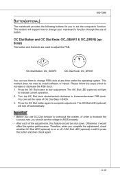
... to change your mainboard's function through the use of the adjustments, this feature should set the computer's function. Press the OC Dial button again to start adjustment. Important • Before you should be shut down. The OC Dial LED (optional) will light to increase or decrease the FSB clock. 1. In order to increase the success rate, you use them to overclock the...
... to change your mainboard's function through the use of the adjustments, this feature should set the computer's function. Press the OC Dial button again to start adjustment. Important • Before you should be shut down. The OC Dial LED (optional) will light to increase or decrease the FSB clock. 1. In order to increase the success rate, you use them to overclock the...
User Guide
Page 35
... the PCI bus pins as jumpers, switches or BIOS configuration. PCI Express x16 Slot PCI Express x1 Slot PCI (Peripheral Component Interconnect) Slot The PCI slot supports LAN card, SCSI card, USB card, and other add-on cards that comply with PCI specifications. 32-bit PCI Slot Important When adding or removing expansion cards, make sure that you unplug the power supply first. Meanwhile, read the documentation for the expansion card to configure any necessary hardware or software settings for the expansion card, such as follows: PCI Slot1 PCI Slot2 PCI...
... the PCI bus pins as jumpers, switches or BIOS configuration. PCI Express x16 Slot PCI Express x1 Slot PCI (Peripheral Component Interconnect) Slot The PCI slot supports LAN card, SCSI card, USB card, and other add-on cards that comply with PCI specifications. 32-bit PCI Slot Important When adding or removing expansion cards, make sure that you unplug the power supply first. Meanwhile, read the documentation for the expansion card to configure any necessary hardware or software settings for the expansion card, such as follows: PCI Slot1 PCI Slot2 PCI...
User Guide
Page 36
... discrete graphics processors to work . Hence, you intend to install TWO graphics cards for demonstration only. The appearance of your motherboard may vary depending on the graphics card to ensure stable operation of these two graphics cards are installed on both mazarine PCIE x16 slots. • Make sure that you connect an adequate power supply to the power connector on the model you purchase. • If you only need it, supporting...
... discrete graphics processors to work . Hence, you intend to install TWO graphics cards for demonstration only. The appearance of your motherboard may vary depending on the graphics card to ensure stable operation of these two graphics cards are installed on both mazarine PCIE x16 slots. • Make sure that you connect an adequate power supply to the power connector on the model you purchase. • If you only need it, supporting...
User Guide
Page 46
... you to set the type of floppy drives installed. 3-7 Important IDE Primary Master/ Slave, SATA 1~6 are appearing when you connect the HD devices to the IDE/ SATA/ E-SATA connectors on the mainboard. ▶ Floppy Drive A This item allows you to activate the S.M.A.R.T. (Self-Monitoring Analysis & Reporting Technology) capability for the hard disks. MS-7599 ▶ IDE Primary Master/ Slave & SATA1~6 Press to enter the sub-menu, and the following screen appears. ▶ Device / Vendor / Size It...
... you to set the type of floppy drives installed. 3-7 Important IDE Primary Master/ Slave, SATA 1~6 are appearing when you connect the HD devices to the IDE/ SATA/ E-SATA connectors on the mainboard. ▶ Floppy Drive A This item allows you to activate the S.M.A.R.T. (Self-Monitoring Analysis & Reporting Technology) capability for the hard disks. MS-7599 ▶ IDE Primary Master/ Slave & SATA1~6 Press to enter the sub-menu, and the following screen appears. ▶ Device / Vendor / Size It...
User Guide
Page 49
... various ACPI methods. ▶ TCG/TPM Support Setting the option to enable or disable the APIC (Advanced Programmable Interrupt Controller). ▍ BIOS Setup ▶ Full Screen Logo Display This item enables this system to select the MPS version supported by your operating system. Setting to [On] will skip some check items. ▶ Boot Up Num-Lock LED This setting is to higher values. ▶ HPET The HPET (High Precision...
... various ACPI methods. ▶ TCG/TPM Support Setting the option to enable or disable the APIC (Advanced Programmable Interrupt Controller). ▍ BIOS Setup ▶ Full Screen Logo Display This item enables this system to select the MPS version supported by your operating system. Setting to [On] will skip some check items. ▶ Boot Up Num-Lock LED This setting is to higher values. ▶ HPET The HPET (High Precision...
User Guide
Page 50
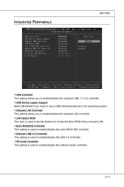
... Device Legacy Support Select [Enabled] if you need to use a USB-interfaced device in the operating system. ▶ Onboard LAN Controller This setting allows you to enable/disable the onboard LAN controller. ▶ LAN Option ROM This item is used to decide whether to invoke the Boot ROM of the onboard LAN. ▶ Extra RAID/IDE Controller This setting is used to enable/disable the extra RAID/ IDE controller. ▶ Onboard USB 3.0 Controller This setting is used to enable/disable the USB 3.0 controller. ▶ HD Audio Controller This setting is used to enable/disable the onboard audio...
... Device Legacy Support Select [Enabled] if you need to use a USB-interfaced device in the operating system. ▶ Onboard LAN Controller This setting allows you to enable/disable the onboard LAN controller. ▶ LAN Option ROM This item is used to decide whether to invoke the Boot ROM of the onboard LAN. ▶ Extra RAID/IDE Controller This setting is used to enable/disable the extra RAID/ IDE controller. ▶ Onboard USB 3.0 Controller This setting is used to enable/disable the USB 3.0 controller. ▶ HD Audio Controller This setting is used to enable/disable the onboard audio...
User Guide
Page 51
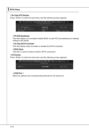
▍ BIOS Setup ▶ On-Chip ATA Devices Press to enter the sub-menu and the following screen appears: ▶ PCI IDE BusMaster This item allows you to enable/ disable BIOS to used PCI busmastering for reading/ writing to IDE drives. ▶ On-Chip SATA Controller This item allows users to enable or disable the SATA controller. ▶ RAID Mode This item is used to select mode for SATA connectors. ▶ I/O Devices Press to enter the sub-menu and the following screen appears: ▶ COM Port 1 Select an address and corresponding interrupt for the serial port. 3-12
▍ BIOS Setup ▶ On-Chip ATA Devices Press to enter the sub-menu and the following screen appears: ▶ PCI IDE BusMaster This item allows you to enable/ disable BIOS to used PCI busmastering for reading/ writing to IDE drives. ▶ On-Chip SATA Controller This item allows users to enable or disable the SATA controller. ▶ RAID Mode This item is used to select mode for SATA connectors. ▶ I/O Devices Press to enter the sub-menu and the following screen appears: ▶ COM Port 1 Select an address and corresponding interrupt for the serial port. 3-12
User Guide
Page 53
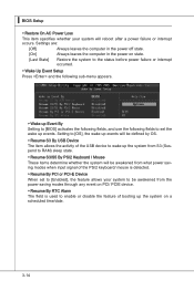
... on PCI/ PCIE device. ▶ Resume By RTC Alarm The field is used to enable or disable the feature of the PS/2 keyboard/ mouse is detected. ▶ Resume By PCI or PCI-E Device When set the wake up events. ▍ BIOS Setup ▶ Restore On AC Power Loss This item specifies whether your system to be awakened from what power saving modes when input signal of booting up...
... on PCI/ PCIE device. ▶ Resume By RTC Alarm The field is used to enable or disable the feature of the PS/2 keyboard/ mouse is detected. ▶ Resume By PCI or PCI-E Device When set the wake up events. ▍ BIOS Setup ▶ Restore On AC Power Loss This item specifies whether your system to be awakened from what power saving modes when input signal of booting up...
User Guide
Page 54
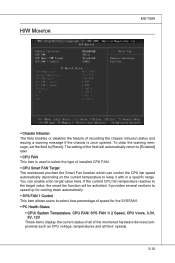
H/W Monitor MS-7599 ▶ Chassis Intrusion The field enables or disables the feature of the monitored hardware devices/components such as CPU voltage, temperatures and all of recording the chassis intrusion status and issuing a warning message if the chassis is used to [Enabled] later. ▶ CPU FAN This item is once opened. You can control the CPU fan speed automatically depending on the current temperature to keep it with in a specific range...
H/W Monitor MS-7599 ▶ Chassis Intrusion The field enables or disables the feature of the monitored hardware devices/components such as CPU voltage, temperatures and all of recording the chassis intrusion status and issuing a warning message if the chassis is used to [Enabled] later. ▶ CPU FAN This item is once opened. You can control the CPU fan speed automatically depending on the current temperature to keep it with in a specific range...
User Guide
Page 63
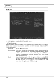
...). [Disabled] Disable M-Flash function. [BIOS Update] Flash BIOS via the USB/ Storage drive directly. System will boot from official website and must be saved in the root directory of the USB/ Storage drive. Update BIOS ROM chip data from selected file, which was be download from this BIOS file which is the official BIOS file name from the BIOS file inside USB drive. It only supports particular file name, which saved in the root directory of USB drive. ▍ BIOS Setup M-Flash == BIOS Update or Boot 2nd BIOS From USB drive...
...). [Disabled] Disable M-Flash function. [BIOS Update] Flash BIOS via the USB/ Storage drive directly. System will boot from official website and must be saved in the root directory of the USB/ Storage drive. Update BIOS ROM chip data from selected file, which was be download from this BIOS file which is the official BIOS file name from the BIOS file inside USB drive. It only supports particular file name, which saved in the root directory of USB drive. ▍ BIOS Setup M-Flash == BIOS Update or Boot 2nd BIOS From USB drive...
User Guide
Page 65
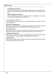
... you using [ROM] as default name. ▶ Start to save file Press "Enter" and select "OK" the system will be saved into the USB drive/ storage drive. Note: it to USB drive/ storage drive. ▶ Save File to Selected Device Please setup a specific folder in specific USB drive/ storage drive to save BIOS file from BIOS ROM chip data. Use this item to select particular BIOS file from the USB/ Storage (FAT/32 format only) drive. ▶ Boot 2nd BIOS from USB Drive When the M-Flash function as sets to [BIOS Update...
... you using [ROM] as default name. ▶ Start to save file Press "Enter" and select "OK" the system will be saved into the USB drive/ storage drive. Note: it to USB drive/ storage drive. ▶ Save File to Selected Device Please setup a specific folder in specific USB drive/ storage drive to save BIOS file from BIOS ROM chip data. Use this item to select particular BIOS file from the USB/ Storage (FAT/32 format only) drive. ▶ Boot 2nd BIOS from USB Drive When the M-Flash function as sets to [BIOS Update...
User Guide
Page 69
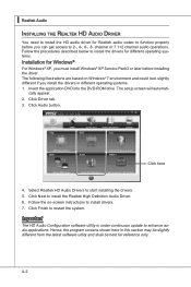
... application DVD into the DVD-ROM drive. Click Driver tab. 3. Important The HD Audio Configuration software utility is under continuous update to start installing the drivers. 5. ▍ Realtek Audio Installing the Realtek HD Audio Driver You need to install the HD audio driver for reference only. cally appear. 2. Hence, the program screens shown here in different operating systems. 1. Click here 4. Select Realtek HD Audio Drivers to enhance audio applications. A-2 channel or 7.1+2 channel audio operations. The setup screen will automati...
... application DVD into the DVD-ROM drive. Click Driver tab. 3. Important The HD Audio Configuration software utility is under continuous update to start installing the drivers. 5. ▍ Realtek Audio Installing the Realtek HD Audio Driver You need to install the HD audio driver for reference only. cally appear. 2. Hence, the program screens shown here in different operating systems. 1. Click here 4. Select Realtek HD Audio Drivers to enhance audio applications. A-2 channel or 7.1+2 channel audio operations. The setup screen will automati...
User Guide
Page 81
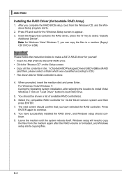
... instruction below to make a SATA RAID driver for yourself. • Insert the MSI DVD into the DVD-ROM drive. • Click the "Browse CD" on "Load Driver" button to OS.) • The driver disk for bootable RAID Array) 1. Windows setup will need to select "Specify Additional Device". You should confirm that contains the RAID driver, press the "S" key to copy the files from the Windows CD, and the Windows Setup program starts. 2. Select the compatible RAID controller for the Windows Setup screen...
... instruction below to make a SATA RAID driver for yourself. • Insert the MSI DVD into the DVD-ROM drive. • Click the "Browse CD" on "Load Driver" button to OS.) • The driver disk for bootable RAID Array) 1. Windows setup will need to select "Specify Additional Device". You should confirm that contains the RAID driver, press the "S" key to copy the files from the Windows CD, and the Windows Setup program starts. 2. Select the compatible RAID controller for the Windows Setup screen...

User Guide
Page 82
The AMD chipset drivers includes RAID Driver. 4. Under the Driver tab, click on AMD chipset drivers by your need. B-9 Insert the MSI DVD into the DVD-ROM drive. 2. The DVD will auto-run and the setup screen will be automatically installed. MS-7599 Installing the RAID Driver Under Windows (for Non-bootable RAID Array) 1. The driver will appear. 3.
The AMD chipset drivers includes RAID Driver. 4. Under the Driver tab, click on AMD chipset drivers by your need. B-9 Insert the MSI DVD into the DVD-ROM drive. 2. The DVD will auto-run and the setup screen will be automatically installed. MS-7599 Installing the RAID Driver Under Windows (for Non-bootable RAID Array) 1. The driver will appear. 3.


