User Guide
Page 3
...separately for air convection hence protects the equipment from overheating. iii CAUTION: Danger of the power source and adjust properly 110/220V before connecting the equipment to the power inlet. ■ Place the power cord such a way that could damage or cause electrical shock. ■ If any ... Manual. ◯ The equipment has dropped and damaged. ◯ The equipment has obvious sign of breakage. thing over the power cord. ■ Always Unplug the Power Cord before inserting any - Do not place any add-on card or module. ■ All cautions and warnings on the ...
...separately for air convection hence protects the equipment from overheating. iii CAUTION: Danger of the power source and adjust properly 110/220V before connecting the equipment to the power inlet. ■ Place the power cord such a way that could damage or cause electrical shock. ■ If any ... Manual. ◯ The equipment has dropped and damaged. ◯ The equipment has obvious sign of breakage. thing over the power cord. ■ Always Unplug the Power Cord before inserting any - Do not place any add-on card or module. ■ All cautions and warnings on the ...
User Guide
Page 4
...equipment has been tested and found to comply with the limits for a Class B digital device, pursuant to operate the equipment. power cord, if any, must accept any interference received, including interference that may cause harmful interference to comply with the emission limits...limits are designed to provide reasonable protection against harmful interference in order to radio communications. Notice 2 Shielded interface cables and A.C. Micro-Star International MS-7549 This device complies with the instructions, may cause undesired operation. However, there is no guarantee that to...
...equipment has been tested and found to comply with the limits for a Class B digital device, pursuant to operate the equipment. power cord, if any, must accept any interference received, including interference that may cause harmful interference to comply with the emission limits...limits are designed to provide reasonable protection against harmful interference in order to radio communications. Notice 2 Shielded interface cables and A.C. Micro-Star International MS-7549 This device complies with the instructions, may cause undesired operation. However, there is no guarantee that to...
User Guide
Page 8
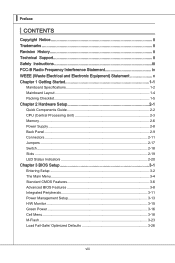
...Started 1-1 Mainboard Specifications 1-2 Mainboard Layout 1-4 Packing Checklist 1-5 Chapter 2 Hardware Setup 2-1 Quick Components Guide 2-2 CPU (Central Processing Unit 2-3 Memory 2-6 Power Supply 2-8 Back Panel 2-9 Connectors 2-11 Jumpers 2-17 Switch 2-18 Slots 2-19 LED Status Indicators 2-20 Chapter 3 BIOS Setup 3-1 Entering Setup ...3-2 The Main Menu 3-4 Standard CMOS Features 3-6 Advanced BIOS Features 3-8 Integrated Peripherals 3-11 Power Management Setup 3-13 H/W Monitor 3-15 Green Power 3-16 Cell Menu 3-18 M-Flash 3-23 Load Fail-Safe/ Optimized Defaults 3-26 viii
...Started 1-1 Mainboard Specifications 1-2 Mainboard Layout 1-4 Packing Checklist 1-5 Chapter 2 Hardware Setup 2-1 Quick Components Guide 2-2 CPU (Central Processing Unit 2-3 Memory 2-6 Power Supply 2-8 Back Panel 2-9 Connectors 2-11 Jumpers 2-17 Switch 2-18 Slots 2-19 LED Status Indicators 2-20 Chapter 3 BIOS Setup 3-1 Entering Setup ...3-2 The Main Menu 3-4 Standard CMOS Features 3-6 Advanced BIOS Features 3-8 Integrated Peripherals 3-11 Power Management Setup 3-13 H/W Monitor 3-15 Green Power 3-16 Cell Menu 3-18 M-Flash 3-23 Load Fail-Safe/ Optimized Defaults 3-26 viii
User Guide
Page 15
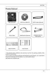
Packing Checklist MS-7549 MSI mainboard MSI Driver/Utility CD SATA Cable (Optional) Power Cable USB Bracket (Optional) Standard Cable for IDE Devices Back IO Shield User's Guide * The pictures are for reference only and may vary from the packing contents of the product you purchased. * If you need to purchase accessories and request the part numbers, you could search the product web page and find details on our web address below http://www.msi.com/index.php 1-5
Packing Checklist MS-7549 MSI mainboard MSI Driver/Utility CD SATA Cable (Optional) Power Cable USB Bracket (Optional) Standard Cable for IDE Devices Back IO Shield User's Guide * The pictures are for reference only and may vary from the packing contents of the product you purchased. * If you need to purchase accessories and request the part numbers, you could search the product web page and find details on our web address below http://www.msi.com/index.php 1-5
User Guide
Page 19
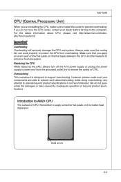
... make sure to install the cooler to prevent overheating. Replacing the CPU While replacing the CPU, always turn off the ATX power supply or unplug the power supply's power cord from overheating. Remember to apply some thermal paste on the computer. MS-7549 CPU (Central Processing Unit) When ...you are able to tolerate such abnormal setting, while doing overclocking. For the latest information about CPU, please visit http://www.msi.com/...
... make sure to install the cooler to prevent overheating. Replacing the CPU While replacing the CPU, always turn off the ATX power supply or unplug the power supply's power cord from overheating. Remember to apply some thermal paste on the computer. MS-7549 CPU (Central Processing Unit) When ...you are able to tolerate such abnormal setting, while doing overclocking. For the latest information about CPU, please visit http://www.msi.com/...
User Guide
Page 24
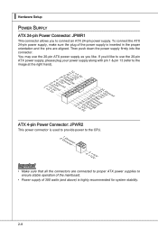
... (and above) is inserted in the proper orientation and the pins are connected to proper ATX power supplies to connect an ATX 24-pin power supply. You may use the 20-pin ATX power supply, please plug your power supply along with pin 1 & pin 13 (refer to the image at the right hand....Wu51nV0R1d.S1+O1B.1+K2211.V+3213.V+4.133.-5V.113.2G6V1V.rP7o1.SuG81-n.rO9Gdo2.NurG0o2n#.ruR1do2n.eu+2ds2n5.+3dV2.5+4V5.GVround ATX 4-pin Power Connector: JPWR2 This power connector is used to provide power to the CPU. 2.G1.rGouronudnd 4.+31.+21V2V Important • Make sure that all the connectors are aligned...
... (and above) is inserted in the proper orientation and the pins are connected to proper ATX power supplies to connect an ATX 24-pin power supply. You may use the 20-pin ATX power supply, please plug your power supply along with pin 1 & pin 13 (refer to the image at the right hand....Wu51nV0R1d.S1+O1B.1+K2211.V+3213.V+4.133.-5V.113.2G6V1V.rP7o1.SuG81-n.rO9Gdo2.NurG0o2n#.ruR1do2n.eu+2ds2n5.+3dV2.5+4V5.GVround ATX 4-pin Power Connector: JPWR2 This power connector is used to provide power to the CPU. 2.G1.rGouronudnd 4.+31.+21V2V Important • Make sure that all the connectors are aligned...
User Guide
Page 28
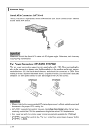
... Monitor chipset on-board, you must use a specially designed fan with speed sensor to one Serial ATA device. Fan Power Connectors: CPUFAN1, SYSFAN1 The fan power connectors support system cooling fan with 3 or 4 pins power connector are both available for proper CPU cooling fan. • CPUFAN1 supports fan control. Fl opMpySDI Fl opMpySDIFlopMpySDI...
... Monitor chipset on-board, you must use a specially designed fan with speed sensor to one Serial ATA device. Fan Power Connectors: CPUFAN1, SYSFAN1 The fan power connectors support system cooling fan with 3 or 4 pins power connector are both available for proper CPU cooling fan. • CPUFAN1 supports fan control. Fl opMpySDI Fl opMpySDIFlopMpySDI...
User Guide
Page 33
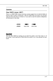
Then return to clear data. 1 JCMOS 1 Keep Data 1 Clear Data Important You can automatically boot OS every time it will damage the mainboard. 2-17 Avoid clearing the CMOS while the system is a CMOS RAM onboard that has a power supply from an external battery to keep the data of system configuration. MS-7549 Jumpers Clear CMOS Jumper: JBAT1 There is on . With the CMOS RAM, the system can clear CMOS by shorting 2-3 pin while the system is turned on ; If you want to clear the system configuration, set the jumper to 1-2 pin position. it is off.
Then return to clear data. 1 JCMOS 1 Keep Data 1 Clear Data Important You can automatically boot OS every time it will damage the mainboard. 2-17 Avoid clearing the CMOS while the system is a CMOS RAM onboard that has a power supply from an external battery to keep the data of system configuration. MS-7549 Jumpers Clear CMOS Jumper: JBAT1 There is on . With the CMOS RAM, the system can clear CMOS by shorting 2-3 pin while the system is turned on ; If you want to clear the system configuration, set the jumper to 1-2 pin position. it is off.
User Guide
Page 34
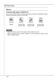
Follow the instructions below to default setting. 2-18 Default Increase 10% speed of FSB Increase 15% speed of FSB Increase 20% speed of FSB Important • Make sure that you power off the system before setting the switch. • When overclocking cause system instability or crash during boot, please set the switch to set the FSB. ▍ Hardware Setup Switch Overclock FSB Switch: OCSWITCH1 You can overclock the FSB to increase the processor frequency by changing the switch.
Follow the instructions below to default setting. 2-18 Default Increase 10% speed of FSB Increase 15% speed of FSB Increase 20% speed of FSB Important • Make sure that you power off the system before setting the switch. • When overclocking cause system instability or crash during boot, please set the switch to set the FSB. ▍ Hardware Setup Switch Overclock FSB Switch: OCSWITCH1 You can overclock the FSB to increase the processor frequency by changing the switch.
User Guide
Page 35
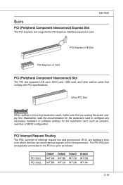
... add-on cards that comply with PCI specifications. 32-bit PCI Slot Important When adding or removing expansion cards, make sure that you unplug the power supply first. The PCI IRQ pins are hardware lines over which devices can send interrupt signals to the microprocessor. PCI Interrupt Request Routing The IRQ...
... add-on cards that comply with PCI specifications. 32-bit PCI Slot Important When adding or removing expansion cards, make sure that you unplug the power supply first. The PCI IRQ pins are hardware lines over which devices can send interrupt signals to the microprocessor. PCI Interrupt Request Routing The IRQ...
User Guide
Page 36
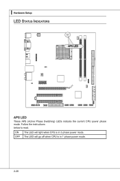
The LED will light when CPU is in 3 phase power mode. Follow the instructions below to read. ▍ Hardware Setup LED Status Indicators APS LED APS LED These APS (Active Phase Switching) LEDs indicate the current CPU power phase mode. ON OFF The LED will go off when CPU is in 1 phase power mode. 2-20
The LED will light when CPU is in 3 phase power mode. Follow the instructions below to read. ▍ Hardware Setup LED Status Indicators APS LED APS LED These APS (Active Phase Switching) LEDs indicate the current CPU power phase mode. ON OFF The LED will go off when CPU is in 1 phase power mode. 2-20
User Guide
Page 38
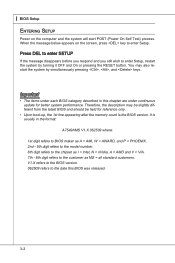
... disappears before you respond and you still wish to enter Setup. When the message below appears on the computer and the system will start POST (Power On Self Test) process. It is the BIOS version. V1.X refers to the BIOS version. 062509 refers to the customer as I = Intel, N = ...2nd - 5th digit refers to the model number. 6th digit refers to the chipset as MS = all standard customers. ▍ BIOS Setup Entering Setup Power on the screen, press key to enter Setup, restart the system by simultaneously pressing , , and keys. You may be slightly different from the latest ...
... disappears before you respond and you still wish to enter Setup. When the message below appears on the computer and the system will start POST (Power On Self Test) process. It is the BIOS version. V1.X refers to the BIOS version. 062509 refers to the customer as I = Intel, N = ...2nd - 5th digit refers to the model number. 6th digit refers to the chipset as MS = all standard customers. ▍ BIOS Setup Entering Setup Power on the screen, press key to enter Setup, restart the system by simultaneously pressing , , and keys. You may be slightly different from the latest ...
User Guide
Page 40
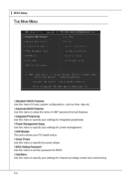
... Use this menu to specify your settings for integrated peripherals. ▶ Power Management Setup Use this menu to specify your settings for power management. ▶ H/W Monitor This entry shows your PC health status. ▶ Green Power Use this menu to specify the power phase. ▶ BIOS Setting Password Use this menu to set the...
... Use this menu to specify your settings for integrated peripherals. ▶ Power Management Setup Use this menu to specify your settings for power management. ▶ H/W Monitor This entry shows your PC health status. ▶ Green Power Use this menu to specify the power phase. ▶ BIOS Setting Password Use this menu to set the...
User Guide
Page 44
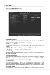
... used to enable or disable the APIC (Advanced Programmable Interrupt Controller). Enabling APIC mode will turn on the Num Lock key when the system is powered on. Setting to [On] will expand available IRQ resources for the system. ▶ MPS Table Version This field allows you enable this item and someone... Features ▶ BIOS Flash Protection When you to select which MPS (Multi-Processor Specification) version to set the Num Lock status when the system is powered on.
... used to enable or disable the APIC (Advanced Programmable Interrupt Controller). Enabling APIC mode will turn on the Num Lock key when the system is powered on. Setting to [On] will expand available IRQ resources for the system. ▶ MPS Table Version This field allows you enable this item and someone... Features ▶ BIOS Flash Protection When you to select which MPS (Multi-Processor Specification) version to set the Num Lock status when the system is powered on.
User Guide
Page 45
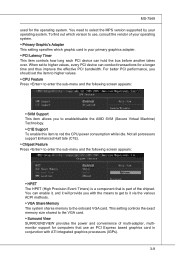
...better PCI performance, you with ATI integrated graphics processors (IGPs). 3-9 You need to the VGA card. ▶ Surround View SURROUNDVIEW provides the power and convenience of the chipset. This setting controls the exact memory size shared to select the MPS version supported by your primary graphics adapter. ...device can enable it, and it via the various ACPI methods. ▶ VGA Share Memory The system shares memory to red the CPU power consumption while idle. Not all porcessors support Enhanced Halt tate (C1E). ▶ Chipset Feature Press to enter the sub-menu and the ...
...better PCI performance, you with ATI integrated graphics processors (IGPs). 3-9 You need to the VGA card. ▶ Surround View SURROUNDVIEW provides the power and convenience of the chipset. This setting controls the exact memory size shared to select the MPS version supported by your primary graphics adapter. ...device can enable it, and it via the various ACPI methods. ▶ VGA Share Memory The system shares memory to red the CPU power consumption while idle. Not all porcessors support Enhanced Halt tate (C1E). ▶ Chipset Feature Press to enter the sub-menu and the ...

User Guide
Page 49
...13 If your operating system supports ACPI, such as Windows 2000/XP, select [Enabled]. ▶ ACPI Standby State This item specifies the power saving modes for ACPI function. In this field. nents turn off button. [Suspend] When you can choose to enter the Standby mode in... and open applications/files is saved to restore the system when a "wake up" event occurs. ▶ Power Button Function This feature sets the function of the power button. Power Management Setup MS-7549 Important S3-related functions described in this section are : [S1] The S1 sleep mode...
...13 If your operating system supports ACPI, such as Windows 2000/XP, select [Enabled]. ▶ ACPI Standby State This item specifies the power saving modes for ACPI function. In this field. nents turn off button. [Suspend] When you can choose to enter the Standby mode in... and open applications/files is saved to restore the system when a "wake up" event occurs. ▶ Power Button Function This feature sets the function of the power button. Power Management Setup MS-7549 Important S3-related functions described in this section are : [S1] The S1 sleep mode...
User Guide
Page 50
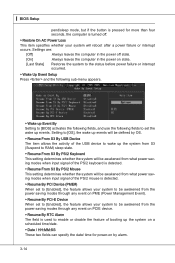
...through any event on PCIE device. ▶ Resume By RTC Alarm The field is used to [Enabled], the feature allows your system will reboot after a power failure or interrupt occurs. Setting to [OS], the wake up events will be defined by alarm. 3-14 ▍ BIOS Setup pend/sleep mode, but ...from S3 (Suspend to RAM) sleep state. ▶ Resume From S3 By PS/2 Keyboard This setting determines whether the system will be awakened from what power saving modes when input signal of the PS/2 keyboard is detected. ▶ Resume From S3 By PS/2 Mouse This setting determines whether the system will...
...through any event on PCIE device. ▶ Resume By RTC Alarm The field is used to [Enabled], the feature allows your system will reboot after a power failure or interrupt occurs. Setting to [OS], the wake up events will be defined by alarm. 3-14 ▍ BIOS Setup pend/sleep mode, but ...from S3 (Suspend to RAM) sleep state. ▶ Resume From S3 By PS/2 Keyboard This setting determines whether the system will be awakened from what power saving modes when input signal of the PS/2 keyboard is detected. ▶ Resume From S3 By PS/2 Mouse This setting determines whether the system will...

User Guide
Page 52
▍ BIOS Setup Green Power ▶ CPU Phase Control When set to [Auto], the hardware will auto adjust the CPU power phase according to the loading of CPU to reach the best power saving function. ▶ LED Power Control This item is used to enable/ disable the power phase LEDs of the mainboard. 3-16
▍ BIOS Setup Green Power ▶ CPU Phase Control When set to [Auto], the hardware will auto adjust the CPU power phase according to the loading of CPU to reach the best power saving function. ▶ LED Power Control This item is used to enable/ disable the power phase LEDs of the mainboard. 3-16
User Guide
Page 55
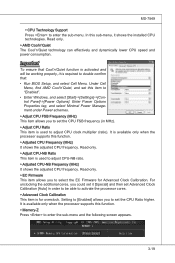
... ▶ Memory-Z Press to set this sub-menu, it [Special] and then set the CPU Ratio higher. Enter Power Options Properties tag, and select Minimal Power Management under Power schemes. ▶ Adjust CPU FSB Frequency (MHz) This item allows you to set Advanced Clock Calibration [Auto] in MHz... cores, you to enter the sub-menu. It is used to "Enabled". • Enter Windows, and select [Start]->[Settings]->[Control Panel]->[Power Options]. Read-only. ▶ EC Firmware This item allows you could set it shows the installed CPU technologies. Read only. ▶ AMD...
... ▶ Memory-Z Press to set this sub-menu, it [Special] and then set the CPU Ratio higher. Enter Power Options Properties tag, and select Minimal Power Management under Power schemes. ▶ Adjust CPU FSB Frequency (MHz) This item allows you to set Advanced Clock Calibration [Auto] in MHz... cores, you to enter the sub-menu. It is used to "Enabled". • Enter Windows, and select [Start]->[Settings]->[Control Panel]->[Power Options]. Read-only. ▶ EC Firmware This item allows you could set it shows the installed CPU technologies. Read only. ▶ AMD...
User Guide
Page 58
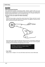
... that the previous overclocking is not recommended. Any risk or damge resulting from failed overclocking... • Reboot Press the Power button to reboot the system three times. Please press any key to continue....... • Clear CMOS Please refer to...default settings automatically. Two ways to "Chapter 2" for some special settings. Warning !!! ▍ BIOS Setup Important Failed Overclocking Resolution This motherboard supports overclocking greatly. Please note that, to avoid electric current to affect other devices or components, we suggest an interval of more information...
... that the previous overclocking is not recommended. Any risk or damge resulting from failed overclocking... • Reboot Press the Power button to reboot the system three times. Please press any key to continue....... • Clear CMOS Please refer to...default settings automatically. Two ways to "Chapter 2" for some special settings. Warning !!! ▍ BIOS Setup Important Failed Overclocking Resolution This motherboard supports overclocking greatly. Please note that, to avoid electric current to affect other devices or components, we suggest an interval of more information...


