User Guide
Page 8
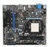
... iii FCC-B Radio Frequency Interference Statement iv WEEE (Waste Electrical and Electronic Equipment) Statement v Chapter 1 Getting Started 1-1 Mainboard Specifications 1-2 Mainboard Layout 1-4 Packing Checklist 1-5 Chapter 2 Hardware Setup 2-1 Quick Components Guide 2-2 CPU (Central Processing Unit 2-3 Memory 2-6 Power Supply 2-8 Back Panel 2-9 Connectors 2-11 Jumpers 2-17 Switch 2-18 Slots 2-19 LED Status Indicators 2-20 Chapter...
... iii FCC-B Radio Frequency Interference Statement iv WEEE (Waste Electrical and Electronic Equipment) Statement v Chapter 1 Getting Started 1-1 Mainboard Specifications 1-2 Mainboard Layout 1-4 Packing Checklist 1-5 Chapter 2 Hardware Setup 2-1 Quick Components Guide 2-2 CPU (Central Processing Unit 2-3 Memory 2-6 Power Supply 2-8 Back Panel 2-9 Connectors 2-11 Jumpers 2-17 Switch 2-18 Slots 2-19 LED Status Indicators 2-20 Chapter...

User Guide
Page 9
MS-7549 Appendix A Realtek Audio A-1 Installing the Realtek HD Audio Driver A-2 Software Configuration A-4 Hardware Setup A-19 Appendix B SB710 RAID B-1 RAID Configuration B-2 Appendix C Dual Core Center C-1 Activating Dual Core Center C-2 Main C-3 DOT (Dynamic OverClocking C-5 Clock C-6 Voltage C-7 FAN Speed C-8 Temperature C-9 User Profile C-10 ix
MS-7549 Appendix A Realtek Audio A-1 Installing the Realtek HD Audio Driver A-2 Software Configuration A-4 Hardware Setup A-19 Appendix B SB710 RAID B-1 RAID Configuration B-2 Appendix C Dual Core Center C-1 Activating Dual Core Center C-2 Main C-3 DOT (Dynamic OverClocking C-5 Clock C-6 Voltage C-7 FAN Speed C-8 Temperature C-9 User Profile C-10 ix
User Guide
Page 17
Static electricity may damage the components. 2-2-1 Chapter 2 Hardware Setup This chapter provides you install in holding the components and follow the installation procedures. For some components, if you with the information about hardware setup procedures. While doing the installation, be careful in the wrong orientation, the components will not work properly. Use a grounded wrist strap before handling computer components.
Static electricity may damage the components. 2-2-1 Chapter 2 Hardware Setup This chapter provides you install in holding the components and follow the installation procedures. For some components, if you with the information about hardware setup procedures. While doing the installation, be careful in the wrong orientation, the components will not work properly. Use a grounded wrist strap before handling computer components.

User Guide
Page 20
... as shown in the correct orientation. 3. As the CPU is likely to move while the lever is being closed, always close the lever. ▍ Hardware Setup CPU & Cooler Installation When you are installing the CPU, make sure the CPU is properly and completely embedded into the socket. 2-4 Pull the lever sideways...
... as shown in the correct orientation. 3. As the CPU is likely to move while the lever is being closed, always close the lever. ▍ Hardware Setup CPU & Cooler Installation When you are installing the CPU, make sure the CPU is properly and completely embedded into the socket. 2-4 Pull the lever sideways...
User Guide
Page 22
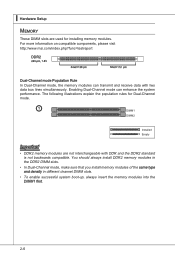
... can transmit and receive data with DDR and the DDR2 standard is not backwards compatible. For more information on compatible components, please visit http://www.msi.com/index.php?func=testreport DDR2 240-pin, 1.8V 64x2=128 pin 56x2=112 pin Dual-Channel mode Population Rule In Dual-Channel mode, the...
... can transmit and receive data with DDR and the DDR2 standard is not backwards compatible. For more information on compatible components, please visit http://www.msi.com/index.php?func=testreport DDR2 240-pin, 1.8V 64x2=128 pin 56x2=112 pin Dual-Channel mode Population Rule In Dual-Channel mode, the...
User Guide
Page 24
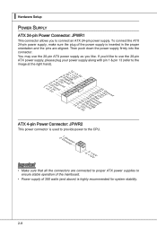
...Setup Power Supply ATX 24-pin Power Connector: JPWR1 This connector allows you to ensure stable operation of the mainboard. • Power supply of the power supply is highly recommended for system stability. 2-8 Then push down the power supply firmly into the connector. If you like to use the 20-pin ATX....r7+do.5uG8Vn.rP9do.Wu51nV0R1d.S1+O1B.1+K2211.V+3213.V+4.133.-5V.113.2G6V1V.rP7o1.SuG81-n.rO9Gdo2.NurG0o2n#.ruR1do2n.eu+2ds2n5.+3dV2.5+4V5.GVround ATX 4-pin Power Connector: JPWR2 This power connector is used to provide power to the CPU. 2.G1.rGouronudnd 4.+31.+21V2V Important •...
...Setup Power Supply ATX 24-pin Power Connector: JPWR1 This connector allows you to ensure stable operation of the mainboard. • Power supply of the power supply is highly recommended for system stability. 2-8 Then push down the power supply firmly into the connector. If you like to use the 20-pin ATX....r7+do.5uG8Vn.rP9do.Wu51nV0R1d.S1+O1B.1+K2211.V+3213.V+4.133.-5V.113.2G6V1V.rP7o1.SuG81-n.rO9Gdo2.NurG0o2n#.ruR1do2n.eu+2ds2n5.+3dV2.5+4V5.GVround ATX 4-pin Power Connector: JPWR2 This power connector is used to provide power to the CPU. 2.G1.rGouronudnd 4.+31.+21V2V Important •...

User Guide
Page 26
▍ Hardware Setup ▶ Audio Ports These audio connectors are used for microphones. ■ RS-Out (Black) - Line Out, is used for speakers or headphones. ■ Mic (Pink) - ...
▍ Hardware Setup ▶ Audio Ports These audio connectors are used for microphones. ■ RS-Out (Black) - Line Out, is used for speakers or headphones. ■ Mic (Pink) - ...
User Guide
Page 28
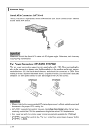
... Kdkldkddfkkakfskkdskkdakaddfdddffdfka-ddkdffdldkddjdafdsdddjfdddffkadadsfdddffdfadasfadfsddsddadasdsaddsdafsddadsdddfdsadddfffaffsfsdasfdfffdf K dk ldkddf kkakfskkdskkdakaddfdddffdfka-ddkdffdldkddj adfdsdddjdfddf kadfadsf dddfafdfdasfsadfddsddadasdsaddsdafsddadsdddfdsadddffffafsfsdafsdf f fdf Important Please do not fold the Serial ATA cable into 90-degree angle. ▍ Hardware Setup Serial ATA Connector: SATA1~6 This connector is the positive and should be connected to the +12V; Otherwise, data loss may select how percentage of the...
... Kdkldkddfkkakfskkdskkdakaddfdddffdfka-ddkdffdldkddjdafdsdddjfdddffkadadsfdddffdfadasfadfsddsddadasdsaddsdafsddadsdddfdsadddfffaffsfsdasfdfffdf K dk ldkddf kkakfskkdskkdakaddfdddffdfka-ddkdffdldkddj adfdsdddjdfddf kadfadsf dddfafdfdasfsadfddsddadasdsaddsdafsddadsdddfdsadddffffafsfsdafsdf f fdf Important Please do not fold the Serial ATA cable into 90-degree angle. ▍ Hardware Setup Serial ATA Connector: SATA1~6 This connector is the positive and should be connected to the +12V; Otherwise, data loss may select how percentage of the...

User Guide
Page 30
▍ Hardware Setup CD-In Connector: JCD1 This connector is a 16550A high speed communication port that sends/ receives 16 bytes FIFOs. To clear the warning, you must enter ...
▍ Hardware Setup CD-In Connector: JCD1 This connector is a 16550A high speed communication port that sends/ receives 16 bytes FIFOs. To clear the warning, you must enter ...

User Guide
Page 32
The parallel port is used to connect an optional parallel port bracket. ▍ Hardware Setup Parallel Port Header: JLPT1 This connector is a standard printer port that supports Enhanced Parallel Port (EPP) and Extended Capabilities Parallel Port (ECP) mode. 2.A4F.ED6R.#P8RI.1N#L0PI1T.TG2#_1r.GoS4u.1LrGon6INurd1.oGn#8ud.r2Gno0dur2.onG2ud2r.1nGo4.du2R.r3Gon6.SudPr.5TNonR.BuPdo7Nn#R.PDdP9NiRn0.DP1N1R1D1.NP32DR.1P35NR1.DP7N41R.DP9N5R2.AD1NC26.DB3K2U7.#P5SE.YSLCT 2-16
The parallel port is used to connect an optional parallel port bracket. ▍ Hardware Setup Parallel Port Header: JLPT1 This connector is a standard printer port that supports Enhanced Parallel Port (EPP) and Extended Capabilities Parallel Port (ECP) mode. 2.A4F.ED6R.#P8RI.1N#L0PI1T.TG2#_1r.GoS4u.1LrGon6INurd1.oGn#8ud.r2Gno0dur2.onG2ud2r.1nGo4.du2R.r3Gon6.SudPr.5TNonR.BuPdo7Nn#R.PDdP9NiRn0.DP1N1R1D1.NP32DR.1P35NR1.DP7N41R.DP9N5R2.AD1NC26.DB3K2U7.#P5SE.YSLCT 2-16
User Guide
Page 34
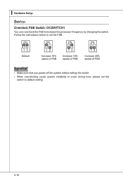
▍ Hardware Setup Switch Overclock FSB Switch: OCSWITCH1 You can overclock the FSB to default setting. 2-18 Follow the instructions below to set the switch to increase the processor frequency by changing the switch. Default Increase 10% speed of FSB Increase 15% speed of FSB Increase 20% speed of FSB Important • Make sure that you power off the system before setting the switch. • When overclocking cause system instability or crash during boot, please set the FSB.
▍ Hardware Setup Switch Overclock FSB Switch: OCSWITCH1 You can overclock the FSB to default setting. 2-18 Follow the instructions below to set the switch to increase the processor frequency by changing the switch. Default Increase 10% speed of FSB Increase 15% speed of FSB Increase 20% speed of FSB Important • Make sure that you power off the system before setting the switch. • When overclocking cause system instability or crash during boot, please set the FSB.
User Guide
Page 36
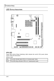
▍ Hardware Setup LED Status Indicators APS LED APS LED These APS (Active Phase Switching) LEDs indicate the current CPU power phase mode. ON OFF The LED will go off when CPU is in 1 phase power mode. 2-20 Follow the instructions below to read. The LED will light when CPU is in 3 phase power mode.
▍ Hardware Setup LED Status Indicators APS LED APS LED These APS (Active Phase Switching) LEDs indicate the current CPU power phase mode. ON OFF The LED will go off when CPU is in 1 phase power mode. 2-20 Follow the instructions below to read. The LED will light when CPU is in 3 phase power mode.
User Guide
Page 37
Chapter 3 BIOS Setup This chapter provides information on the screen during the system booting up, and requests you to change the default settings for optimum use. You may need to run the Setup program when: ■ An error message appears on the BIOS Setup program and allows you to run SETUP. ■ You want to configure the system for customized features. 2-3-1
Chapter 3 BIOS Setup This chapter provides information on the screen during the system booting up, and requests you to change the default settings for optimum use. You may need to run the Setup program when: ■ An error message appears on the BIOS Setup program and allows you to run SETUP. ■ You want to configure the system for customized features. 2-3-1
User Guide
Page 38
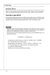
...up, the 1st line appearing after the memory count is usually in this BIOS was released. 3-2 ▍ BIOS Setup Entering Setup Power on the screen, press key to enter Setup. You may be slightly different from the latest BIOS and should be held for better system performance. Important •...the chipset as I = Intel, N = nVidia, A = AMD and V = VIA. 7th - 8th digit refers to enter Setup, restart the system by simultaneously pressing , , and keys. Press DEL to enter SETUP If the message disappears before you respond and you still wish to the customer as MS = all standard customers...
...up, the 1st line appearing after the memory count is usually in this BIOS was released. 3-2 ▍ BIOS Setup Entering Setup Power on the screen, press key to enter Setup. You may be slightly different from the latest BIOS and should be held for better system performance. Important •...the chipset as I = Intel, N = nVidia, A = AMD and V = VIA. 7th - 8th digit refers to enter Setup, restart the system by simultaneously pressing , , and keys. Press DEL to enter SETUP If the message disappears before you respond and you still wish to the customer as MS = all standard customers...

User Guide
Page 39
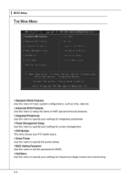
...screen from any menu by simply pressing . Press to select the item. General Help The BIOS setup program provides a General Help screen. Main Menu The main menu lists the setup functions you can make changes General Help Enter CPU Specifications submenu Enter Memory-Z submenu Load Optimized ...Defaults Load Fail-Safe Defaults Save all the CMOS changes and exit Getting Help After entering the Setup menu, the first menu you find a right pointer symbol (as shown in the right hand Select the item Jumps to the ...
...screen from any menu by simply pressing . Press to select the item. General Help The BIOS setup program provides a General Help screen. Main Menu The main menu lists the setup functions you can make changes General Help Enter CPU Specifications submenu Enter Memory-Z submenu Load Optimized ...Defaults Load Fail-Safe Defaults Save all the CMOS changes and exit Getting Help After entering the Setup menu, the first menu you find a right pointer symbol (as shown in the right hand Select the item Jumps to the ...
User Guide
Page 40
...CMOS Features Use this menu for basic system configurations, such as time, date etc. ▶ Advanced BIOS Features Use this menu to setup the items of AMI® special enhanced features. ▶ Integrated Peripherals Use this menu to specify your settings for integrated peripherals. ▶... Power Management Setup Use this menu to specify your settings for power management. ▶ H/W Monitor This entry shows your PC health status. ▶ Green...
...CMOS Features Use this menu for basic system configurations, such as time, date etc. ▶ Advanced BIOS Features Use this menu to setup the items of AMI® special enhanced features. ▶ Integrated Peripherals Use this menu to specify your settings for integrated peripherals. ▶... Power Management Setup Use this menu to specify your settings for power management. ▶ H/W Monitor This entry shows your PC health status. ▶ Green...

User Guide
Page 41
MS-7549 ▶ M-Flash Use this menu to read/ flash the BIOS from storage drive (FAT/ FAT32 format only). ▶ Load Fail-Safe Defaults Use this menu to load the default values set by the BIOS vendor for stable system performance. ▶ Load Optimized Defaults Use this menu to load the default values set by the mainboard manufacturer specifically for optimal performance of the mainboard. ▶ Save & Exit Setup Save changes to CMOS and exit setup. ▶ Exit Without Saving Abandon all changes and exit setup. 3-5
MS-7549 ▶ M-Flash Use this menu to read/ flash the BIOS from storage drive (FAT/ FAT32 format only). ▶ Load Fail-Safe Defaults Use this menu to load the default values set by the BIOS vendor for stable system performance. ▶ Load Optimized Defaults Use this menu to load the default values set by the mainboard manufacturer specifically for optimal performance of the mainboard. ▶ Save & Exit Setup Save changes to CMOS and exit setup. ▶ Exit Without Saving Abandon all changes and exit setup. 3-5

User Guide
Page 42
... want (usually the current time). year The year can be adjusted by numeric function keys. Readonly. ▍ BIOS Setup Standard CMOS Features The items in Standard CMOS Features Menu includes some basic setup items. Use the arrow keys to highlight the item and then use the or keys to select the value...
... want (usually the current time). year The year can be adjusted by numeric function keys. Readonly. ▍ BIOS Setup Standard CMOS Features The items in Standard CMOS Features Menu includes some basic setup items. Use the arrow keys to highlight the item and then use the or keys to select the value...
User Guide
Page 44
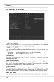
... check items. ▶ Boot Up Num Lock LED This setting is to set the Num Lock status when the system is powered on. ▍ BIOS Setup Advanced BIOS Features ▶ BIOS Flash Protection When you to select which MPS (Multi-Processor Specification) version to be 3-8 Setting to [Off] will alarm beep...
... check items. ▶ Boot Up Num Lock LED This setting is to set the Num Lock status when the system is powered on. ▍ BIOS Setup Advanced BIOS Features ▶ BIOS Flash Protection When you to select which MPS (Multi-Processor Specification) version to be 3-8 Setting to [Off] will alarm beep...
User Guide
Page 46
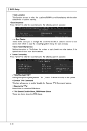
.../ disable the Execute TPM Command feature. ▶ Clearing the TPM Press Enter to enter the sub-menu and the following screen appears: ▶ --- ▍ BIOS Setup ▶ UMA Location This function is used to select the location of UMA to avoid overlaping with the other data blocks in system memory. ▶...
.../ disable the Execute TPM Command feature. ▶ Clearing the TPM Press Enter to enter the sub-menu and the following screen appears: ▶ --- ▍ BIOS Setup ▶ UMA Location This function is used to select the location of UMA to avoid overlaping with the other data blocks in system memory. ▶...

