
User Guide
Page 4
...if any interference received, including interference that may cause harmful interference to provide reasonable protection against harmful interference in a particular installation. iv However, there is no guarantee that to comply with Part 15 of the FCC Rules. If this device must ...determined by turning the equipment off and on a circuit different from that interference will not occur in a residential installation. Micro-Star International MS-7596 This device complies with the emission limits. Notice 1 The changes or modifications not expressly approved by one or ...
...if any interference received, including interference that may cause harmful interference to provide reasonable protection against harmful interference in a particular installation. iv However, there is no guarantee that to comply with Part 15 of the FCC Rules. If this device must ...determined by turning the equipment off and on a circuit different from that interference will not occur in a residential installation. Micro-Star International MS-7596 This device complies with the emission limits. Notice 1 The changes or modifications not expressly approved by one or ...

User Guide
Page 9
MS-7596 User Settings 3-27 Load Fail-Safe/ Optimized Defaults 3-28 Appendix A Realtek Audio A-1 Installing the Realtek HD Audio Driver A-2 Software Configuration A-4 Hardware Setup A-19 Appendix B SB710 RAID B-1 RAID Configuration B-2 Appendix C Overclocking Center C-1 Activating Overclocking Center C-2 System Info C-3 DOT C-5 ix
MS-7596 User Settings 3-27 Load Fail-Safe/ Optimized Defaults 3-28 Appendix A Realtek Audio A-1 Installing the Realtek HD Audio Driver A-2 Software Configuration A-4 Hardware Setup A-19 Appendix B SB710 RAID B-1 RAID Configuration B-2 Appendix C Overclocking Center C-1 Activating Overclocking Center C-2 System Info C-3 DOT C-5 ix

User Guide
Page 16
While doing the installation, be careful in the wrong orientation, the components will not work properly. Static electricity may damage the components. 2-2-1 Use a grounded wrist strap before handling computer components. Chapter 2 Hardware Setup This chapter provides you install in holding the components and follow the installation procedures. For some components, if you with the information about hardware setup procedures.
While doing the installation, be careful in the wrong orientation, the components will not work properly. Static electricity may damage the components. 2-2-1 Use a grounded wrist strap before handling computer components. Chapter 2 Hardware Setup This chapter provides you install in holding the components and follow the installation procedures. For some components, if you with the information about hardware setup procedures.

User Guide
Page 18
MS-7596 CPU (Central Processing Unit) When you are able to operate beyond product specifications. 2-3 Replacing the CPU While replacing the CPU, always turn off the ATX power supply or unplug the power supply's power cord from overheating. php?func=cpuform2 Important Overheating Overheating will.... If you apply an even layer of CPU. For the latest information about CPU, please visit http://www.msi.com/index. Always make sure to install the cooler to support overclocking. Any attempt to tolerate such abnormal setting, while doing overclocking. However, please make...
MS-7596 CPU (Central Processing Unit) When you are able to operate beyond product specifications. 2-3 Replacing the CPU While replacing the CPU, always turn off the ATX power supply or unplug the power supply's power cord from overheating. php?func=cpuform2 Important Overheating Overheating will.... If you apply an even layer of CPU. For the latest information about CPU, please visit http://www.msi.com/index. Always make sure to install the cooler to support overclocking. Any attempt to tolerate such abnormal setting, while doing overclocking. However, please make...

User Guide
Page 19
... cause the damage of the CPU to make sure the CPU has a cooler attached on the top to move while the lever is correctly installed, the pins should point as shown in the correct orientation. 3. The CPU can not be completely embedded into the socket and can only ... to prevent overheating. The gold arrow should be seen. Please note that any violation of the CPU. ▍ Hardware Setup CPU & Cooler Installation When you are installing the CPU, make sure the CPU is properly and completely embedded into the socket. 2-4 Pull the lever sideways away from the socket. Follow...
... cause the damage of the CPU to make sure the CPU has a cooler attached on the top to move while the lever is correctly installed, the pins should point as shown in the correct orientation. 3. The CPU can not be completely embedded into the socket and can only ... to prevent overheating. The gold arrow should be seen. Please note that any violation of the CPU. ▍ Hardware Setup CPU & Cooler Installation When you are installing the CPU, make sure the CPU is properly and completely embedded into the socket. 2-4 Pull the lever sideways away from the socket. Follow...

User Guide
Page 21
...please visit http://www.msi.com/index.php?func=testreport DDR3 240-pin, 1.5V 72x2=144 pin 48x2=96 pin Dual-Channel mode Population Rule In Dual-Channel mode, the memory modules can enhance the system performance. The following illustrations explain the population rules for installing memory modules. You... the DIMM1 first. • Due to the chipset resource deployment, the system density will only be detected up to 15+GB (not full 16GB) when each DIMM is not backwards compatible. Enabling Dual-Channel mode can transmit and receive data with two data bus lines simultaneously. ▍...
...please visit http://www.msi.com/index.php?func=testreport DDR3 240-pin, 1.5V 72x2=144 pin 48x2=96 pin Dual-Channel mode Population Rule In Dual-Channel mode, the memory modules can enhance the system performance. The following illustrations explain the population rules for installing memory modules. You... the DIMM1 first. • Due to the chipset resource deployment, the system density will only be detected up to 15+GB (not full 16GB) when each DIMM is not backwards compatible. Enabling Dual-Channel mode can transmit and receive data with two data bus lines simultaneously. ▍...

User Guide
Page 22
.... Insert the memory module vertically into the DIMM slot. Manually check if the memory module has been locked in the DIMM slot. Notch Volt 2-7 MS-7596 Installing Memory Modules 1. Then push it in until the golden finger on the center and will automatically close when the memory module is deeply inserted in...
.... Insert the memory module vertically into the DIMM slot. Manually check if the memory module has been locked in the DIMM slot. Notch Volt 2-7 MS-7596 Installing Memory Modules 1. Then push it in until the golden finger on the center and will automatically close when the memory module is deeply inserted in...
User Guide
Page 26
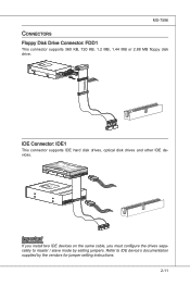
... i veConnector CD-RMOSMI Kdkldkddfkkakfskkdskkdakaddfdddffdfkadd-kdffdldkddjdafdsdddjdfddfdfkaadsfdddffdfadasfsadfddsddadasdsaddsdafsddadsdddfdsadddfffaffsfsdasfdfffdf 3 1/2" F loppy Di sk D r ive Connector Important If you install two IDE devices on the same cable, you must configure the drives separately to IDE device's documentation supplied by... ri ve Connector IDE Connector: IDE1 This connector supports IDE hard disk drives, optical disk drives and other IDE devices. MS-7596 Connectors Floppy Disk Drive Connector: FDD1 This connector supports 360 KB, 720 KB, 1.2 MB, 1.44 MB or 2.88 MB...
... i veConnector CD-RMOSMI Kdkldkddfkkakfskkdskkdakaddfdddffdfkadd-kdffdldkddjdafdsdddjdfddfdfkaadsfdddffdfadasfsadfddsddadasdsaddsdafsddadsdddfdsadddfffaffsfsdasfdfffdf 3 1/2" F loppy Di sk D r ive Connector Important If you install two IDE devices on the same cable, you must configure the drives separately to IDE device's documentation supplied by... ri ve Connector IDE Connector: IDE1 This connector supports IDE hard disk drives, optical disk drives and other IDE devices. MS-7596 Connectors Floppy Disk Drive Connector: FDD1 This connector supports 360 KB, 720 KB, 1.2 MB, 1.44 MB or 2.88 MB...
User Guide
Page 28
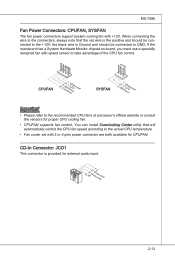
... use a specially designed fan with +12V. the black wire is Ground and should be connected to GND. You can install Overclocking Center utility that the red wire is provided for CPUFAN. MS-7596 Fan Power Connectors: CPUFAN, SYSFAN The fan power connectors support system cooling fan with speed sensor to take advantage...
... use a specially designed fan with +12V. the black wire is Ground and should be connected to GND. You can install Overclocking Center utility that the red wire is provided for CPUFAN. MS-7596 Fan Power Connectors: CPUFAN, SYSFAN The fan power connectors support system cooling fan with speed sensor to take advantage...
User Guide
Page 35
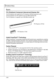
...8482; HD 3400 Series or ATI Mobility Radeon™ HD 3400 Series graphics processor. 3. After then, power on the system and install the driver that supports Hybrid CrossFireX™ technology. PCI Express x16 Slot PCI Express x1 Slot Hybrid CrossFireX™ Technology Hybrid CrossFireX™...; technology brings multi-GPU performance capabilities by enabling an AMD® integrated graphics processor and a discrete graphics processor to show in Catalyst Control Center: 2-20 Click this icon. Graphic card based...
...8482; HD 3400 Series or ATI Mobility Radeon™ HD 3400 Series graphics processor. 3. After then, power on the system and install the driver that supports Hybrid CrossFireX™ technology. PCI Express x16 Slot PCI Express x1 Slot Hybrid CrossFireX™ Technology Hybrid CrossFireX™...; technology brings multi-GPU performance capabilities by enabling an AMD® integrated graphics processor and a discrete graphics processor to show in Catalyst Control Center: 2-20 Click this icon. Graphic card based...
User Guide
Page 46
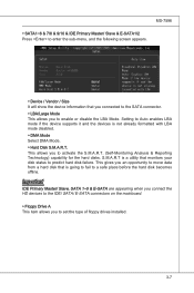
... disk that is going to fail to a safe place before the hard disk becomes offline. This gives you to set the type of floppy drives installed. 3-7 MS-7596 ▶ SATA1~6 & 7/8 & 9/10 & IDE Primary Master/ Slave & E-SATA1/2 Press to enter the sub-menu, and the following screen appears. ▶ Device / Vendor / Size It...
... disk that is going to fail to a safe place before the hard disk becomes offline. This gives you to set the type of floppy drives installed. 3-7 MS-7596 ▶ SATA1~6 & 7/8 & 9/10 & IDE Primary Master/ Slave & E-SATA1/2 Press to enter the sub-menu, and the following screen appears. ▶ Device / Vendor / Size It...

User Guide
Page 58
Read-only. ▶ CPU Specifications Press to enter the sub-menu and the following screen appears. This submenu shows the information of CPU and Memory speed. Cell Menu MS-7596 Important Change these settings only if you are familiar with the chipset. ▶ Current CPU / DRAM Frequency These items show the current clocks of installed CPU. 3-19
Read-only. ▶ CPU Specifications Press to enter the sub-menu and the following screen appears. This submenu shows the information of CPU and Memory speed. Cell Menu MS-7596 Important Change these settings only if you are familiar with the chipset. ▶ Current CPU / DRAM Frequency These items show the current clocks of installed CPU. 3-19

User Guide
Page 59
Under Cell Menu, find AMD Cool'n'Quiet, and set this item to enter the sub-menu and the following screen appears. This submenu shows the technologies that : • Run BIOS ... Cell Menu. Important To ensure that Cool'n'Quiet function is activated and will be working properly, it is required to double confirm that the installed CPU supported. ▶ AMD Cool'n'Quiet The Cool'n'Quiet technology can effectively and dynamically lower CPU speed and power consumption. Enter Power Options Properties tag, and select...
Under Cell Menu, find AMD Cool'n'Quiet, and set this item to enter the sub-menu and the following screen appears. This submenu shows the technologies that : • Run BIOS ... Cell Menu. Important To ensure that Cool'n'Quiet function is activated and will be working properly, it is required to double confirm that the installed CPU supported. ▶ AMD Cool'n'Quiet The Cool'n'Quiet technology can effectively and dynamically lower CPU speed and power consumption. Enter Power Options Properties tag, and select...

User Guide
Page 60
... try the lower FSB clock for overclock. Read-only. ▶ Adjust CPU-NB Ratio This item is used to adjust CPU clock multiplier (ratio). MS-7596 ▶ Adjust CPU FSB Frequency (MHz) This item allows you to select the CPU Front Side Bus clock frequency (in MHz). ▶ Adjust CPU Ratio... adjusted CPU NB frequency. Setting to [Enabled] allows you to enter the sub-menu and the following screen appears. This submenu displays the information of installed memory. ▶ Advance DRAM Configuration Press to set the CPU Ratio higher.
... try the lower FSB clock for overclock. Read-only. ▶ Adjust CPU-NB Ratio This item is used to adjust CPU clock multiplier (ratio). MS-7596 ▶ Adjust CPU FSB Frequency (MHz) This item allows you to select the CPU Front Side Bus clock frequency (in MHz). ▶ Adjust CPU Ratio... adjusted CPU NB frequency. Setting to [Enabled] allows you to enter the sub-menu and the following screen appears. This submenu displays the information of installed memory. ▶ Advance DRAM Configuration Press to set the CPU Ratio higher.

User Guide
Page 69
...audio applications. Follow the procedures described below to install the drivers for different operating systems. Installation for Windows® XP For Windows® XP, you can get access to 2-, 4-, 6-, 8- ▍ Realtek Audio Installing the Realtek HD Audio Driver You need to install the HD audio driver for Realtek audio codec... driver. The following illustrations are based on Windows® XP environment and could look slightly different if you install the drivers in this section may be slightly different from the latest software utility and shall be held for reference only. ...
...audio applications. Follow the procedures described below to install the drivers for different operating systems. Installation for Windows® XP For Windows® XP, you can get access to 2-, 4-, 6-, 8- ▍ Realtek Audio Installing the Realtek HD Audio Driver You need to install the HD audio driver for Realtek audio codec... driver. The following illustrations are based on Windows® XP environment and could look slightly different if you install the drivers in this section may be slightly different from the latest software utility and shall be held for reference only. ...

User Guide
Page 70
Click here Select this option Click here Click here A-3 3. Click Next to restart the system. MS-7596 4. Click Finish to install the Realtek High Definition Audio Driver.
Click here Select this option Click here Click here A-3 3. Click Next to restart the system. MS-7596 4. Click Finish to install the Realtek High Definition Audio Driver.

User Guide
Page 71
Click the audio icon from the Control Panel. It is also available to enable the audio driver by clicking the Realtek HD Audio Manager from the system tray at the lower-right corner of the screen to use the 2-, 4-, 6- Double click A-4 channel audio feature now. or 8- ▍ Realtek Audio Software Configuration After installing the audio driver, you are able to activate the HD Audio Configuration.
Click the audio icon from the Control Panel. It is also available to enable the audio driver by clicking the Realtek HD Audio Manager from the system tray at the lower-right corner of the screen to use the 2-, 4-, 6- Double click A-4 channel audio feature now. or 8- ▍ Realtek Audio Software Configuration After installing the audio driver, you are able to activate the HD Audio Configuration.

User Guide
Page 89
▍ Realtek Audio ■ 8-Channel Mode for Stereo-Speaker Output 1] Line In 2] Line Out (Front channels) 3] MIC 4] Line Out (Rear channels) 5] Line Out (Center and Subwoofer channel) 6] Line Out (Side channels) Important To enable 7.1 channel audio-out function on Windows Vista operating system, you have to install the Realtek Audio Driver. Or, the mainboard will support 5.1 channel audio-out only. A-22
▍ Realtek Audio ■ 8-Channel Mode for Stereo-Speaker Output 1] Line In 2] Line Out (Front channels) 3] MIC 4] Line Out (Rear channels) 5] Line Out (Center and Subwoofer channel) 6] Line Out (Side channels) Important To enable 7.1 channel audio-out function on Windows Vista operating system, you have to install the Realtek Audio Driver. Or, the mainboard will support 5.1 channel audio-out only. A-22

User Guide
Page 97
... For Windows Vista: During the Operating system installation, after the RAID volume is done. 4. Select the compatible RAID controller for bootable RAID Array) 1. tinue. 9. ▍ SB710 RAID Installing the RAID Driver (for 32-bit/ 64-...next screen should be shown a list of available SCSI Adapters. 6. for Windows Vista: \\ChipSet\AMD\VISTA\Packages\Drivers\SBDrv\SB7xx\RAID\ x86 (for 32bit) or x64(for 64bit) • The driver disk for... yourself. • Insert the MSI DVD into the DVD-ROM drive. • Click the "Browse DVD" on "Load Driver...
... For Windows Vista: During the Operating system installation, after the RAID volume is done. 4. Select the compatible RAID controller for bootable RAID Array) 1. tinue. 9. ▍ SB710 RAID Installing the RAID Driver (for 32-bit/ 64-...next screen should be shown a list of available SCSI Adapters. 6. for Windows Vista: \\ChipSet\AMD\VISTA\Packages\Drivers\SBDrv\SB7xx\RAID\ x86 (for 32bit) or x64(for 64bit) • The driver disk for... yourself. • Insert the MSI DVD into the DVD-ROM drive. • Click the "Browse DVD" on "Load Driver...
User Guide
Page 98
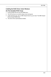
MS-7596 Installing the RAID Driver Under Windows (for Non-bootable RAID Array) 1. B-9 The DVD will auto-run and the setup screen will be automatically installed. Insert the MSI DVD into the DVD-ROM drive. 2. Under the Driver tab, click on AMD chipset drivers by your need. The AMD chipset drivers include RAID Driver. 4. The driver will appear. 3.
MS-7596 Installing the RAID Driver Under Windows (for Non-bootable RAID Array) 1. B-9 The DVD will auto-run and the setup screen will be automatically installed. Insert the MSI DVD into the DVD-ROM drive. 2. Under the Driver tab, click on AMD chipset drivers by your need. The AMD chipset drivers include RAID Driver. 4. The driver will appear. 3.


