
User Guide
Page 2
... the user's manual, please contact your system and no guarantee is a registered trademark of purchase or local distributor. Trademarks All trademarks are under continual improvement and we reserve the right to the correctness of MICRO-STAR INTERNATIONAL. Revision History Revision V1.4 Revision History Release for FAQ, technical guide, BIOS updates, driver updates, and other information: http://www.msi.com...
... the user's manual, please contact your system and no guarantee is a registered trademark of purchase or local distributor. Trademarks All trademarks are under continual improvement and we reserve the right to the correctness of MICRO-STAR INTERNATIONAL. Revision History Revision V1.4 Revision History Release for FAQ, technical guide, BIOS updates, driver updates, and other information: http://www.msi.com...

User Guide
Page 8
... 1 Getting Started 1-1 Mainboard Specifications 1-2 Mainboard Layout 1-4 Packing Checklist 1-5 Chapter 2 Hardware Setup 2-1 Quick Components Guide 2-2 CPU (Central Processing Unit 2-3 Memory 2-6 Power Supply 2-8 Back Panel 2-9 Connectors 2-11 Jumpers 2-18 Switch 2-19 Slots 2-20 LED Status Indicators 2-23 Chapter 3 BIOS Setup 3-1 Entering Setup 3-2 The Main Menu 3-4 Standard CMOS Features 3-6 Advanced BIOS Features 3-9 Integrated Peripherals 3-12 Power Management Setup 3-14 H/W Monitor 3-16 Green Power 3-17 BIOS Setting Password 3-18 Cell Menu 3-19 M-Flash 3-24 viii
... 1 Getting Started 1-1 Mainboard Specifications 1-2 Mainboard Layout 1-4 Packing Checklist 1-5 Chapter 2 Hardware Setup 2-1 Quick Components Guide 2-2 CPU (Central Processing Unit 2-3 Memory 2-6 Power Supply 2-8 Back Panel 2-9 Connectors 2-11 Jumpers 2-18 Switch 2-19 Slots 2-20 LED Status Indicators 2-23 Chapter 3 BIOS Setup 3-1 Entering Setup 3-2 The Main Menu 3-4 Standard CMOS Features 3-6 Advanced BIOS Features 3-9 Integrated Peripherals 3-12 Power Management Setup 3-14 H/W Monitor 3-16 Green Power 3-17 BIOS Setting Password 3-18 Cell Menu 3-19 M-Flash 3-24 viii

User Guide
Page 11
... 8-channel audio with jack sensing ■ Compliant with Azalia 1.0 Spec IDE ■ 1 IDE port by AMD® SB710 ■ Supports Ultra DMA 66/100/133 mode ■ Supports PIO, Bus Master operation mode SATA ■ 5 SATAII ports by AMD® SB710 ■ 1 E-SATA port by AMD® SB710 ■ Supports storage and data transfers at up to 3 Gb/s RAID ■ SATA 1~5 supports RAID 0/ 1/ 0+1 or JBOD mode by AMD® SB710 1-2 ▍ Getting Started Mainboard Specifications Processor Support ■ AMD® 64 bits PhenomTM...
... 8-channel audio with jack sensing ■ Compliant with Azalia 1.0 Spec IDE ■ 1 IDE port by AMD® SB710 ■ Supports Ultra DMA 66/100/133 mode ■ Supports PIO, Bus Master operation mode SATA ■ 5 SATAII ports by AMD® SB710 ■ 1 E-SATA port by AMD® SB710 ■ Supports storage and data transfers at up to 3 Gb/s RAID ■ SATA 1~5 supports RAID 0/ 1/ 0+1 or JBOD mode by AMD® SB710 1-2 ▍ Getting Started Mainboard Specifications Processor Support ■ AMD® 64 bits PhenomTM...
User Guide
Page 23
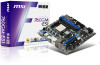
....5+4V5.GVround ATX 4-pin Power Connector: JPWR2 This connector is used to provide power to the CPU. 2.G1.rGouronudnd 4.+31.+21V2V Important • Make sure that all the connectors are aligned. If you'd like . Then push down the power supply firmly into the connector. ▍ Hardware Setup Power Supply ATX 24-pin Power Connector: JPWR1 This connector allows you to ensure stable operation of the mainboard. • Power supply of the power supply is inserted...
....5+4V5.GVround ATX 4-pin Power Connector: JPWR2 This connector is used to provide power to the CPU. 2.G1.rGouronudnd 4.+31.+21V2V Important • Make sure that all the connectors are aligned. If you'd like . Then push down the power supply firmly into the connector. ▍ Hardware Setup Power Supply ATX 24-pin Power Connector: JPWR1 This connector allows you to ensure stable operation of the mainboard. • Power supply of the power supply is inserted...
User Guide
Page 24
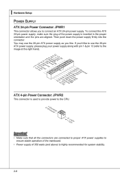
... LCD monitor, simply plug your monitor cable into the DVI-D connector, and make sure that the other USB-compatible devices. ▶ HDMI Port The High-Definition Multimedia Interface (HDMI) is an all-digital audio/video interface capable of transmitting uncompressed streams. HDMI supports all TV format, including standard, enhanced, or high-definition video, plus multi-channel digital audio on a single cable. ▶ E-SATA Port The E-SATA (External-SATA) port is provided for attaching the E-SATA hard drive. 2-9 It provides a high-speed...
... LCD monitor, simply plug your monitor cable into the DVI-D connector, and make sure that the other USB-compatible devices. ▶ HDMI Port The High-Definition Multimedia Interface (HDMI) is an all-digital audio/video interface capable of transmitting uncompressed streams. HDMI supports all TV format, including standard, enhanced, or high-definition video, plus multi-channel digital audio on a single cable. ▶ E-SATA Port The E-SATA (External-SATA) port is provided for attaching the E-SATA hard drive. 2-9 It provides a high-speed...
User Guide
Page 26
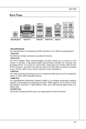
...adfdsdddjdfddf fkadadsf dddffdfadasfadfsddsddadasdsaddsdafsddadsdddfdsadddffffafsfsdafsdf ff df 3 1/2" Fl oppy Disk Dr i veConnector CD-RMOSMI Kdkldkddfkkakfskkdskkdakaddfdddffdfkadd-kdffdldkddjdafdsdddjdfddfdfkaadsfdddffdfadasfsadfddsddadasdsaddsdafsddadsdddfdsadddfffaffsfsdasfdfffdf 3 1/2" F loppy Di sk D r ive Connector Important If you install two IDE devices on the same cable, you must configure the drives separately to IDE device's documentation supplied by setting jumpers. MS-7596 Connectors Floppy Disk Drive Connector: FDD1 This connector supports 360 KB, 720 KB, 1.2 MB, 1.44 MB...
...adfdsdddjdfddf fkadadsf dddffdfadasfadfsddsddadasdsaddsdafsddadsdddfdsadddffffafsfsdafsdf ff df 3 1/2" Fl oppy Disk Dr i veConnector CD-RMOSMI Kdkldkddfkkakfskkdskkdakaddfdddffdfkadd-kdffdldkddjdafdsdddjdfddfdfkaadsfdddffdfadasfsadfddsddadasdsaddsdafsddadsdddfdsadddfffaffsfsdasfdfffdf 3 1/2" F loppy Di sk D r ive Connector Important If you install two IDE devices on the same cable, you must configure the drives separately to IDE device's documentation supplied by setting jumpers. MS-7596 Connectors Floppy Disk Drive Connector: FDD1 This connector supports 360 KB, 720 KB, 1.2 MB, 1.44 MB...
User Guide
Page 28
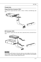
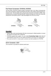
... the recommended CPU fans at processor's official website or consult the vendors for CPUFAN. If the mainboard has a System Hardware Monitor chipset on-board, you must use a specially designed fan with +12V. the black wire is Ground and should be connected to GND. MS-7596 Fan Power Connectors: CPUFAN, SYSFAN The fan power connectors support system cooling fan with speed sensor to take advantage of the CPU fan control. When connecting the wire to the...
... the recommended CPU fans at processor's official website or consult the vendors for CPUFAN. If the mainboard has a System Hardware Monitor chipset on-board, you must use a specially designed fan with +12V. the black wire is Ground and should be connected to GND. MS-7596 Fan Power Connectors: CPUFAN, SYSFAN The fan power connectors support system cooling fan with speed sensor to take advantage of the CPU fan control. When connecting the wire to the...
User Guide
Page 33
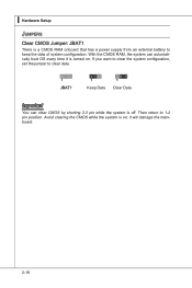
▍ Hardware Setup Jumpers Clear CMOS Jumper: JBAT1 There is off. If you want to clear the system configuration, set the jumper to clear data. 1 JBAT1 1 Keep Data 1 Clear Data Important You can automatically boot OS every time it will damage the mainboard. 2-18 Then return to keep the data of system configuration. Avoid clearing the CMOS while the system is turned on ; it is on . With the CMOS RAM, the system can clear CMOS by shorting 2-3 pin while the system is a CMOS RAM onboard that has a power supply from an external battery to 1-2 pin position.
▍ Hardware Setup Jumpers Clear CMOS Jumper: JBAT1 There is off. If you want to clear the system configuration, set the jumper to clear data. 1 JBAT1 1 Keep Data 1 Clear Data Important You can automatically boot OS every time it will damage the mainboard. 2-18 Then return to keep the data of system configuration. Avoid clearing the CMOS while the system is turned on ; it is on . With the CMOS RAM, the system can clear CMOS by shorting 2-3 pin while the system is a CMOS RAM onboard that has a power supply from an external battery to 1-2 pin position.

User Guide
Page 35
... for blisteringly-fast frame rates. Unleash the graphics performance. Graphic card based on an AMD® integrated chipset. The PCI Express 2.0 x16 supports up to 8.0 GB/s transfer rate. ▍ Hardware Setup Slots PCI (Peripheral Component Interconnect) Express Slot The PCI Express slot supports the PCI Express interface expansion card. Mainboard based on an ATI Radeon™ HD 2400 Series2, ATI Radeon™ HD 3400 Series or ATI Mobility Radeon™ HD 3400 Series graphics processor. 3.
... for blisteringly-fast frame rates. Unleash the graphics performance. Graphic card based on an AMD® integrated chipset. The PCI Express 2.0 x16 supports up to 8.0 GB/s transfer rate. ▍ Hardware Setup Slots PCI (Peripheral Component Interconnect) Express Slot The PCI Express slot supports the PCI Express interface expansion card. Mainboard based on an ATI Radeon™ HD 2400 Series2, ATI Radeon™ HD 3400 Series or ATI Mobility Radeon™ HD 3400 Series graphics processor. 3.

User Guide
Page 37
... configure any necessary hardware or software settings for the expansion card, such as follows: PCI Slot1 PCI Slot2 Order1 INT E# INT F# Order2 INT F# INT G# Order3 INT G# INT H# Order4 INT H# INT E# 2-22 Meanwhile, read the documentation for the expansion card to the microprocessor. ▍ Hardware Setup PCI (Peripheral Component Interconnect) Slot The PCI slot supports LAN card, SCSI card, USB card, and other add-on cards that comply with PCI specifications. 32-bit PCI Slot...
... configure any necessary hardware or software settings for the expansion card, such as follows: PCI Slot1 PCI Slot2 Order1 INT E# INT F# Order2 INT F# INT G# Order3 INT G# INT H# Order4 INT H# INT E# 2-22 Meanwhile, read the documentation for the expansion card to the microprocessor. ▍ Hardware Setup PCI (Peripheral Component Interconnect) Slot The PCI slot supports LAN card, SCSI card, USB card, and other add-on cards that comply with PCI specifications. 32-bit PCI Slot...

User Guide
Page 46
... the following screen appears. ▶ Device / Vendor / Size It will show the device information that monitors your disk status to predict hard disk failure. This allows you to set the type of floppy drives installed. 3-7 Important IDE Primary Master/ Slave, SATA 1~5 & E-SATA are appearing when you connect the HD devices to the IDE/ SATA/ E-SATA connectors on the mainboard. ▶ Floppy Drive A This item allows you to enable or disable the LBA Mode. Setting to a safe place before the hard disk becomes offline...
... the following screen appears. ▶ Device / Vendor / Size It will show the device information that monitors your disk status to predict hard disk failure. This allows you to set the type of floppy drives installed. 3-7 Important IDE Primary Master/ Slave, SATA 1~5 & E-SATA are appearing when you connect the HD devices to the IDE/ SATA/ E-SATA connectors on the mainboard. ▶ Floppy Drive A This item allows you to enable or disable the LBA Mode. Setting to a safe place before the hard disk becomes offline...

User Guide
Page 49
... PCI bandwidth. ▍ BIOS Setup ▶ IOAPIC Function This field is used to enable/ disable SVM. ▶ Chipset Feature Press to enter the sub-menu and the following screen appears: ▶ C1E Support To enable this item to read the CPU power consumption while idle. You need to select the MPS version supported by your primary graphics adapter. ▶ PCI Latency Timer This item controls how long each PCI device can to enable...
... PCI bandwidth. ▍ BIOS Setup ▶ IOAPIC Function This field is used to enable/ disable SVM. ▶ Chipset Feature Press to enter the sub-menu and the following screen appears: ▶ C1E Support To enable this item to read the CPU power consumption while idle. You need to select the MPS version supported by your primary graphics adapter. ▶ PCI Latency Timer This item controls how long each PCI device can to enable...

User Guide
Page 51
...; BIOS Setup Integrated Peripherals ▶ USB Controller This setting allows you to enable/disable the onboard USB 1.1/ 2.0 controller. ▶ USB Device Legacy Support Select [Enabled] if you need to use a USB-interfaced device in the operating system. ▶ Onboard LAN Controller This setting allows you to enable/disable the onboard LAN controller. ▶ LAN Option ROM This item is used to decide whether to invoke the Boot ROM of the onboard LAN. ▶ HD Audio Controller This setting is used to enable/disable the onboard audio controller. ▶ On-Chip ATA Devices Press to enter...
...; BIOS Setup Integrated Peripherals ▶ USB Controller This setting allows you to enable/disable the onboard USB 1.1/ 2.0 controller. ▶ USB Device Legacy Support Select [Enabled] if you need to use a USB-interfaced device in the operating system. ▶ Onboard LAN Controller This setting allows you to enable/disable the onboard LAN controller. ▶ LAN Option ROM This item is used to decide whether to invoke the Boot ROM of the onboard LAN. ▶ HD Audio Controller This setting is used to enable/disable the onboard audio controller. ▶ On-Chip ATA Devices Press to enter...
User Guide
Page 52
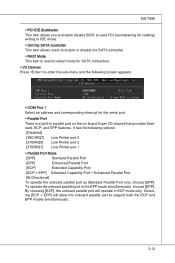
... to enable/ disable BIOS to used PCI busmastering for reading/ writing to IDE drives. ▶ OnChip SATA Controller This item allows users to enable or disable the SATA controller. ▶ RAID Mode This item is used to select mode for SATA connectors. ▶ I/O Devices Press to support both the ECP and EPP modes simultaneously. 3-13 Choosing [ECP + EPP] will operate in ECP mode only. By choosing [ECP], the onboard parallel port will allow the onboard parallel port to enter...
... to enable/ disable BIOS to used PCI busmastering for reading/ writing to IDE drives. ▶ OnChip SATA Controller This item allows users to enable or disable the SATA controller. ▶ RAID Mode This item is used to select mode for SATA connectors. ▶ I/O Devices Press to support both the ECP and EPP modes simultaneously. 3-13 Choosing [ECP + EPP] will operate in ECP mode only. By choosing [ECP], the onboard parallel port will allow the onboard parallel port to enter...
User Guide
Page 53
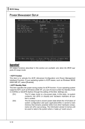
... Power Management Interface) Function. Settings are available only when the BIOS supports S3 sleep mode. ▶ ACPI Function This item is to restore the system when a "wake up" event occurs. 3-14 ▍ BIOS Setup Power Management Setup Important S3-related functions described in this state, no system context is lost (CPU or chipset) and hardware maintains all sys- If your operating system supports ACPI, such as Windows...
... Power Management Interface) Function. Settings are available only when the BIOS supports S3 sleep mode. ▶ ACPI Function This item is to restore the system when a "wake up" event occurs. 3-14 ▍ BIOS Setup Power Management Setup Important S3-related functions described in this state, no system context is lost (CPU or chipset) and hardware maintains all sys- If your operating system supports ACPI, such as Windows...
User Guide
Page 54
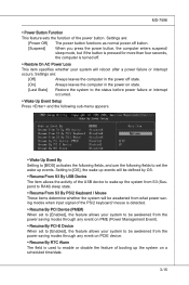
... before power failure or interrupt occurred. ▶ Wake Up Event Setup Press and the following sub-menu appears. ▶ Wake Up Event By Setting to [BIOS] activates the following fields, and use the following fields to set to [Enabled], the feature allows your system to enable or disable the feature of the power button. MS-7596 ▶ Power Button Function This feature sets the function of booting up events. Settings...
... before power failure or interrupt occurred. ▶ Wake Up Event Setup Press and the following sub-menu appears. ▶ Wake Up Event By Setting to [BIOS] activates the following fields, and use the following fields to set to [Enabled], the feature allows your system to enable or disable the feature of the power button. MS-7596 ▶ Power Button Function This feature sets the function of booting up events. Settings...

User Guide
Page 55
... allows users to [Reset]. To clear the warning message, set the field to select how percentage of speed for the SYSFAN1. ▶ PC Health Status ▶ CPU/ System Temperature, CPU FAN/ SYS FAN 1 Speed, CPU Vcore, 3.3V, 5V, 12V These items display the current status of all fans' speeds. 3-16 ▍ BIOS Setup H/W Monitor ▶ Chassis Intrusion The field enables or disables the feature of the monitored hardware devices/components such as CPU voltage, temperatures and...
... allows users to [Reset]. To clear the warning message, set the field to select how percentage of speed for the SYSFAN1. ▶ PC Health Status ▶ CPU/ System Temperature, CPU FAN/ SYS FAN 1 Speed, CPU Vcore, 3.3V, 5V, 12V These items display the current status of all fans' speeds. 3-16 ▍ BIOS Setup H/W Monitor ▶ Chassis Intrusion The field enables or disables the feature of the monitored hardware devices/components such as CPU voltage, temperatures and...

User Guide
Page 65
...; Start to save it only supports FAT/ FAT32 file system drive. ▶ Save File Name as Please setup a specific extend name for the BIOS file, which will be saved into the USB drive/ storage drive. Note: we suggest you using the official name as the default name. ▶ Save Extend File name as Please setup a specific name for the BIOS file, which will stare to save the onboard ROM chip data to [Boot] or [BIOS Update...
...; Start to save it only supports FAT/ FAT32 file system drive. ▶ Save File Name as Please setup a specific extend name for the BIOS file, which will be saved into the USB drive/ storage drive. Note: we suggest you using the official name as the default name. ▶ Save Extend File name as Please setup a specific name for the BIOS file, which will stare to save the onboard ROM chip data to [Boot] or [BIOS Update...

User Guide
Page 97
... the RAID controller. ▍ SB710 RAID Installing the RAID Driver (for 32-bit/ 64-bit version system and then press ENTER. 7. Select the compatible RAID controller for bootable RAID Array) 1. After you can copy the files to a medium (floppy/ CD/ DVD or USB) Important Please follow the instruction below to make a SATA RAID driver for RAID controller is formatted, and Windows setup starts copying files. Press F6 and wait for Windows XP: \\ChipSet\AMD\XP\SBDrv\RAID7xx - for the Windows Setup screen to continue. 8. Windows setup...
... the RAID controller. ▍ SB710 RAID Installing the RAID Driver (for 32-bit/ 64-bit version system and then press ENTER. 7. Select the compatible RAID controller for bootable RAID Array) 1. After you can copy the files to a medium (floppy/ CD/ DVD or USB) Important Please follow the instruction below to make a SATA RAID driver for RAID controller is formatted, and Windows setup starts copying files. Press F6 and wait for Windows XP: \\ChipSet\AMD\XP\SBDrv\RAID7xx - for the Windows Setup screen to continue. 8. Windows setup...

User Guide
Page 98
Insert the MSI DVD into the DVD-ROM drive. 2. The AMD chipset drivers include RAID Driver. 4. MS-7596 Installing the RAID Driver Under Windows (for Non-bootable RAID Array) 1. The driver will appear. 3. Under the Driver tab, click on AMD chipset drivers by your need. The DVD will auto-run and the setup screen will be automatically installed. B-9
Insert the MSI DVD into the DVD-ROM drive. 2. The AMD chipset drivers include RAID Driver. 4. MS-7596 Installing the RAID Driver Under Windows (for Non-bootable RAID Array) 1. The driver will appear. 3. Under the Driver tab, click on AMD chipset drivers by your need. The DVD will auto-run and the setup screen will be automatically installed. B-9

