
User Guide
Page 5
...2-3 CPU Core Speed Derivation Procedure 2-3 Memory Speed/CPU FSB Support Matrix 2-3 CPU Installation Procedures for Socket 478 2-4 Installing the CPU Fan 2-5 Memory 2-7 Introduction to DDR SDRAM 2-7 DDR Module Combination 2-8 Installing DDR Modules 2-8 Power Supply 2-9 ATX 20-Pin Power Connector: CONN1 2-9 ATX 12V Power Connector: JPW1 2-9 Back Panel 2-10 Mouse Connector 2-10 Keyboard Connector 2-11 USB Connectors 2-11 Serial Port Connector 2-12 VGA Connector 2-12 IEEE 1394 Port (Optional 2-12 RJ-45 LAN Jack 2-13 v Getting Started 1-1 Mainboard Specifications 1-2 Mainboard...
...2-3 CPU Core Speed Derivation Procedure 2-3 Memory Speed/CPU FSB Support Matrix 2-3 CPU Installation Procedures for Socket 478 2-4 Installing the CPU Fan 2-5 Memory 2-7 Introduction to DDR SDRAM 2-7 DDR Module Combination 2-8 Installing DDR Modules 2-8 Power Supply 2-9 ATX 20-Pin Power Connector: CONN1 2-9 ATX 12V Power Connector: JPW1 2-9 Back Panel 2-10 Mouse Connector 2-10 Keyboard Connector 2-11 USB Connectors 2-11 Serial Port Connector 2-12 VGA Connector 2-12 IEEE 1394 Port (Optional 2-12 RJ-45 LAN Jack 2-13 v Getting Started 1-1 Mainboard Specifications 1-2 Mainboard...
User Guide
Page 7
...4-3 RAID 1 (Mirror array 4-3 JBOD (Spanning array 4-3 System BIOS Setup 4-4 BIOS Configuration 4-5 Starting BIOS Utility 4-5 Create a RAID 0 (Stripe) Array for performance 4-8 Create a RAID 1 (Mirror) Array for performance 4-12 Create a JBOD Array for performance 4-16 Delete a RAID array 4-18 Installing Software 4-21 Install Driver in Windows XP/2000 4-21 Installation of SiS SATA RAID Driver 4-22 vii Power Management Setup 3-17 PNP/PCI Configurations 3-21 PC Health Status 3-23 Frequency/Voltage Control 3-24 Load Fail-Safe/Optimized Defaults 3-25 Set Supervisor/User Password...
...4-3 RAID 1 (Mirror array 4-3 JBOD (Spanning array 4-3 System BIOS Setup 4-4 BIOS Configuration 4-5 Starting BIOS Utility 4-5 Create a RAID 0 (Stripe) Array for performance 4-8 Create a RAID 1 (Mirror) Array for performance 4-12 Create a JBOD Array for performance 4-16 Delete a RAID array 4-18 Installing Software 4-21 Install Driver in Windows XP/2000 4-21 Installation of SiS SATA RAID Driver 4-22 vii Power Management Setup 3-17 PNP/PCI Configurations 3-21 PC Health Status 3-23 Frequency/Voltage Control 3-24 Load Fail-Safe/Optimized Defaults 3-25 Set Supervisor/User Password...
User Guide
Page 10
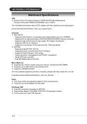
....msi.com.tw/program/ products/mainboard/mbd/pro_mbd_cpu_support.php ) Chipset h SiS ® 661FX - h Support Bus Master, Ultra DMA 33/66/100/133 operation modes. Supports HyperTransport Technology - h Three PCI 2.2 32-bit Master PCI Bus slots. h Can connect up to four IDE devices. 1-2 Supports bi-directional 16-bit data bus with AC97 interface - Advanced power management and PC2001 compliance - On-Board IDE h Dual IDE controllers integrated in SiS® 964. Dual IDE Master/Slave Controller Main Memory h Supports two memory banks using two 184-pin...
....msi.com.tw/program/ products/mainboard/mbd/pro_mbd_cpu_support.php ) Chipset h SiS ® 661FX - h Support Bus Master, Ultra DMA 33/66/100/133 operation modes. Supports HyperTransport Technology - h Three PCI 2.2 32-bit Master PCI Bus slots. h Can connect up to four IDE devices. 1-2 Supports bi-directional 16-bit data bus with AC97 interface - Advanced power management and PC2001 compliance - On-Board IDE h Dual IDE controllers integrated in SiS® 964. Dual IDE Master/Slave Controller Main Memory h Supports two memory banks using two 184-pin...

User Guide
Page 11
Can support SPDIF out via a 3-pin SPDIF-Out pinheader. h Realtek 8201BL LAN PHY. h IEEE 802.3 and 802.3x Standard Compatible h Supports ACPI v1.0b and PCI power management v1.1 Standard BIOS h 4MB Award BIOS with AC97 2.3 Spec - Comply with PNP BIOS, ACPI, SMBIOS 2.3, Green and Boot Block. Mounting h 9 mounting holes. 1-3 Meets PC2001 audio performance requirement - h Provides DMI 2.0, WFM 2.0, WOL, WOR, chassis intrusion, and SMBus for system management. Dimension h Micro-ATX Form Factor: 9.6 inch...
Can support SPDIF out via a 3-pin SPDIF-Out pinheader. h Realtek 8201BL LAN PHY. h IEEE 802.3 and 802.3x Standard Compatible h Supports ACPI v1.0b and PCI power management v1.1 Standard BIOS h 4MB Award BIOS with AC97 2.3 Spec - Comply with PNP BIOS, ACPI, SMBIOS 2.3, Green and Boot Block. Mounting h 9 mounting holes. 1-3 Meets PC2001 audio performance requirement - h Provides DMI 2.0, WFM 2.0, WOL, WOR, chassis intrusion, and SMBus for system management. Dimension h Micro-ATX Form Factor: 9.6 inch...

User Guide
Page 24
... 1394 Port (Optional) The back panel provides one 9-pin male DIN connector. You can attach a serial mouse or other PCs, and portable devices. 1394 Port 2-12 The standard IEEE 1394 port connects to it. MS-7060 Micro ATX Mainboard Serial Port Connector The mainboard offers one standard IEEE 1394 port. The IEEE 1394 high-speed serial bus complements USB by providing enhanced PC connectivity for a wide range of devices, including consumer electronics audio/video (A/V) appliances, storage peripherals, other serial device...
... 1394 Port (Optional) The back panel provides one 9-pin male DIN connector. You can attach a serial mouse or other PCs, and portable devices. 1394 Port 2-12 The standard IEEE 1394 port connects to it. MS-7060 Micro ATX Mainboard Serial Port Connector The mainboard offers one standard IEEE 1394 port. The IEEE 1394 high-speed serial bus complements USB by providing enhanced PC connectivity for a wide range of devices, including consumer electronics audio/video (A/V) appliances, storage peripherals, other serial device...
User Guide
Page 32
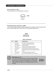
... front panel audio connector allows you don't want to connect to the front audio header, pins 5 & 6, 9 & 10 have to be jumpered in order to have signal output directed to the rear audio ports. MS-7060 Micro ATX Mainboard CD-In Connector: JCD1 The connector is for future use to control headphone amplifier 8 KEY No pin 9 AUD_FPOUT_L Left channel audio signal to the front panel audio and is compliant with Intel® Front Panel I/O Connectivity Design Guide...
... front panel audio connector allows you don't want to connect to the front audio header, pins 5 & 6, 9 & 10 have to be jumpered in order to have signal output directed to the rear audio ports. MS-7060 Micro ATX Mainboard CD-In Connector: JCD1 The connector is for future use to control headphone amplifier 8 KEY No pin 9 AUD_FPOUT_L Left channel audio signal to the front panel audio and is compliant with Intel® Front Panel I/O Connectivity Design Guide...
User Guide
Page 34
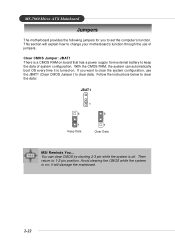
... 1 Clear Data MSI Reminds You... With the CMOS RAM, the system can clear CMOS by shorting 2-3 pin while the system is a CMOS RAM on ; You can automatically boot OS every time it will explain how to change your motherboard's function through the use the JBAT1 (Clear CMOS Jumper ) to clear data. it is on board that has a power supply from external battery to keep the data of jumpers. Follow the instructions below to 1-2 pin position...
... 1 Clear Data MSI Reminds You... With the CMOS RAM, the system can clear CMOS by shorting 2-3 pin while the system is a CMOS RAM on ; You can automatically boot OS every time it will explain how to change your motherboard's function through the use the JBAT1 (Clear CMOS Jumper ) to clear data. it is on board that has a power supply from external battery to keep the data of jumpers. Follow the instructions below to 1-2 pin position...

User Guide
Page 35
... adding or removing expansion cards, make any necessary hardware or software settings for the graphics controller to make sure that you unplug the power supply first. Hardware Setup Slots The motherboard provides one AGP slot, three 32-bit PCI bus slots. AGP is an interface specification designed for the throughput demands of interrupt request line and pronounced I-R-Q, are typically connected to the microprocessor. AGP (Accelerated Graphics Port) Slot The AGP slot allows...
... adding or removing expansion cards, make any necessary hardware or software settings for the graphics controller to make sure that you unplug the power supply first. Hardware Setup Slots The motherboard provides one AGP slot, three 32-bit PCI bus slots. AGP is an interface specification designed for the throughput demands of interrupt request line and pronounced I-R-Q, are typically connected to the microprocessor. AGP (Accelerated Graphics Port) Slot The AGP slot allows...

User Guide
Page 41
...-only. The year can be keyed by users. IDE Primary/Secondary Master/Slave Press PgUp/ or PgDn/ to Sat, determined by BIOS. The date from Jan. Note that the specifications of the week, from Sun to select [Manual], [None] or [Auto] type. The hard disk will not work properly if you want in Standard CMOS Features Menu are divided into 11 categories. Date...
...-only. The year can be keyed by users. IDE Primary/Secondary Master/Slave Press PgUp/ or PgDn/ to Sat, determined by BIOS. The date from Jan. Note that the specifications of the week, from Sun to select [Manual], [None] or [Auto] type. The hard disk will not work properly if you want in Standard CMOS Features Menu are divided into 11 categories. Date...
User Guide
Page 44
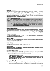
...) at which the keys are accelerated. This gives you to Enabled. CPU L3 Cache This item is a utility that supports L3 Cache; Setting options: [Enabled], [Disabled]. Seek Floppy Setting to [Off] will turn on . BIOS Setup Hard Disk S.M.A.R.T. Setting options: [Auto], [Enabled], [Disabled]. Setting to [Enabled] will swap floppy drives A: and B:. Setting options: [Enabled], [Disabled]. e.g. S.M.A.R.T is only for CPU that monitors your disk status to set USB Keyboard/Mouse Support in SiS OnChip PCI Device of the USB-interface devices, please set the Num Lock...
...) at which the keys are accelerated. This gives you to Enabled. CPU L3 Cache This item is a utility that supports L3 Cache; Setting options: [Enabled], [Disabled]. Seek Floppy Setting to [Off] will turn on . BIOS Setup Hard Disk S.M.A.R.T. Setting options: [Auto], [Enabled], [Disabled]. Setting to [Enabled] will swap floppy drives A: and B:. Setting options: [Enabled], [Disabled]. e.g. S.M.A.R.T is only for CPU that monitors your disk status to set USB Keyboard/Mouse Support in SiS OnChip PCI Device of the USB-interface devices, please set the Num Lock...
User Guide
Page 45
... guide, the system is powered on or when end users try to run in APIC mode. To find out which version to use other OS except Windows NT, you to select which MPS (Multi-Processor Specification) version to be used to run the OS/2® operating system with HT Technology; *Chipset: A chipset that supports HT Technology; *BIOS: A BIOS that is used for the system. Boot OS/2 for your operating system. Setting options: [Enabled], [Disabled]. A password...
... guide, the system is powered on or when end users try to run in APIC mode. To find out which version to use other OS except Windows NT, you to select which MPS (Multi-Processor Specification) version to be used to run the OS/2® operating system with HT Technology; *Chipset: A chipset that supports HT Technology; *BIOS: A BIOS that is used for the system. Boot OS/2 for your operating system. Setting options: [Enabled], [Disabled]. A password...

User Guide
Page 48
AGP Fast Write Support This option [Enabled] or [Disabled] the AGP Fast Write feature. OnChip AGP Control Press and the following sub-menu appears: BIOS Setup AGP Aperture Size This setting controls just how much system RAM can be allocated to AGP for video memory, from [16] to [128] MB. The option allows the selection of an aperture size of the PCI memory address range dedicated to graphics memory address space...
AGP Fast Write Support This option [Enabled] or [Disabled] the AGP Fast Write feature. OnChip AGP Control Press and the following sub-menu appears: BIOS Setup AGP Aperture Size This setting controls just how much system RAM can be allocated to AGP for video memory, from [16] to [128] MB. The option allows the selection of an aperture size of the PCI memory address range dedicated to graphics memory address space...
User Guide
Page 50
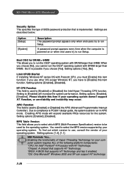
... USB peripherals. BIOS Setup IDE DMA transfer access Setting to invoke the Boot ROM of the Onboard LAN Chip. Disable the controller if you have any USB driver installed, such as DOS and SCO Unix. Setting options: [Disabled], [Enabled]. SiS Serial ATA controller This allows you need to use other controller cards to use a USB keyboard/mouse in DOS, which will be enabled; SiS 10/100M Ethernet This item is used to enable or disable onchip Serial ATA controller. Setting options: [Auto], [Disabled]. USB Keyboard/Mouse Support Set to [Enabled] if you to enable/disable...
... USB peripherals. BIOS Setup IDE DMA transfer access Setting to invoke the Boot ROM of the Onboard LAN Chip. Disable the controller if you have any USB driver installed, such as DOS and SCO Unix. Setting options: [Disabled], [Enabled]. SiS Serial ATA controller This allows you need to use other controller cards to use a USB keyboard/mouse in DOS, which will be enabled; SiS 10/100M Ethernet This item is used to enable or disable onchip Serial ATA controller. Setting options: [Auto], [Disabled]. USB Keyboard/Mouse Support Set to [Enabled] if you to enable/disable...

User Guide
Page 58
... current temperature reaches to Reset. This item is hardware monitoring mechanism onboard. Setting options: [Enabled], [Reset], [Disabled]. The setting of the field will slow down . Setting options: Min: [0](oC), Max: [100](oC). BIOS Setup PC Health Status This section shows the status of your mainboard has JCI1 jumper. To clear the warning message, set here), the fan will shotdown automatically. 3-23 Shutdown Temperature If the CPU temperature reaches the limit preset in the "Smart Fan...
... current temperature reaches to Reset. This item is hardware monitoring mechanism onboard. Setting options: [Enabled], [Reset], [Disabled]. The setting of the field will slow down . Setting options: Min: [0](oC), Max: [100](oC). BIOS Setup PC Health Status This section shows the status of your mainboard has JCI1 jumper. To clear the warning message, set here), the fan will shotdown automatically. 3-23 Shutdown Temperature If the CPU temperature reaches the limit preset in the "Smart Fan...
User Guide
Page 59
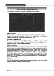
.... Setting options: [Enabled], [Disabled]. MS-7060 Micro ATX Mainboard Frequency/Voltage Control Use this menu to specify your overclocked processor to lock up. CPU Frequency Use this field. Remember to minimize the electromagnetic interference (EMI). Auto Detect DIMM/PCI Clk This item is set to [Enabled], the system will remove (turn off) clocks from empty PCI slots to disable Spread Spectrum if you are overclocking because even a slight jitter can overclock the processor (only if the processor supports so) by EMI, set to [Enabled...
.... Setting options: [Enabled], [Disabled]. MS-7060 Micro ATX Mainboard Frequency/Voltage Control Use this menu to specify your overclocked processor to lock up. CPU Frequency Use this field. Remember to minimize the electromagnetic interference (EMI). Auto Detect DIMM/PCI Clk This item is set to [Enabled], the system will remove (turn off) clocks from empty PCI slots to disable Spread Spectrum if you are overclocking because even a slight jitter can overclock the processor (only if the processor supports so) by EMI, set to [Enabled...

User Guide
Page 65
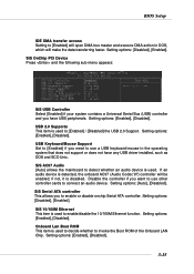
... Controller to enter Setup. MS-7060 Micro ATX Mainboard System BIOS Setup Power on the computer and the system will appear on the screen. When the message below appears on the Main Menu and press to enter SETUP If the message disappears before you respond and you enter BIOS Setup Utility, the Main Menu will start POST (Power On Self Test) process. For Award BIOS: Press DEL to enter Integrated Peripherals. Use arrow keys to move among the configurable...
... Controller to enter Setup. MS-7060 Micro ATX Mainboard System BIOS Setup Power on the computer and the system will appear on the screen. When the message below appears on the Main Menu and press to enter SETUP If the message disappears before you respond and you enter BIOS Setup Utility, the Main Menu will start POST (Power On Self Test) process. For Award BIOS: Press DEL to enter Integrated Peripherals. Use arrow keys to move among the configurable...
User Guide
Page 82
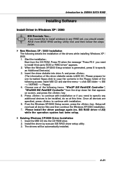
... of the following details the installation of this time. SiS RAID driver v1.02) while the operation system has been setup. Setup will be installed, do so at this driver diskette exists in MSI CD. Start the installation: Boot from BIOS RAID setting Utility first and then follow the steps below. Once all device files and then continue the Windows XP/2000 installation. 7. Insert the driver diskette into the CD-ROM drive. 2.
... of the following details the installation of this time. SiS RAID driver v1.02) while the operation system has been setup. Setup will be installed, do so at this driver diskette exists in MSI CD. Start the installation: Boot from BIOS RAID setting Utility first and then follow the steps below. Once all device files and then continue the Windows XP/2000 installation. 7. Insert the driver diskette into the CD-ROM drive. 2.
User Guide
Page 83
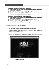
... driver SiS 964 IDE Dual Channel should appear. Choose the Hardware tab, then click the Device Manager tab. 3. The driver SiS 964 RAID Controller should appear. Click the "+" in front of SiS SATA RAID Driver SiS RAID driver supports Microsoft Windows XP/2000/ME/98SE. Insert the MSI CD and click on the SiS SATA RAID Driver to install the software. 4-22 Click on this item MS-7060 Micro ATX Mainboard h Confirming Windows XP/2000 Driver Installation...
... driver SiS 964 IDE Dual Channel should appear. Choose the Hardware tab, then click the Device Manager tab. 3. The driver SiS 964 RAID Controller should appear. Click the "+" in front of SiS SATA RAID Driver SiS RAID driver supports Microsoft Windows XP/2000/ME/98SE. Insert the MSI CD and click on the SiS SATA RAID Driver to install the software. 4-22 Click on this item MS-7060 Micro ATX Mainboard h Confirming Windows XP/2000 Driver Installation...
User Guide
Page 85
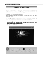
... Windows® 2000, you must install Windows® 2000 Service Pack2 or later before you can get access to function properly before installing the driver. A-2 MS-7060 Micro ATX Mainboard Installing the Audio Driver You need to install the driver for Realtek ALC655 chip to 4-/6-channel audio operations. Follow the procedures described below might be held for reference only. Insert the companion CD into the CD-ROM drive. The AC97 Audio Configuration software utility...
... Windows® 2000, you must install Windows® 2000 Service Pack2 or later before you can get access to function properly before installing the driver. A-2 MS-7060 Micro ATX Mainboard Installing the Audio Driver You need to install the driver for Realtek ALC655 chip to 4-/6-channel audio operations. Follow the procedures described below might be held for reference only. Insert the companion CD into the CD-ROM drive. The AC97 Audio Configuration software utility...
User Guide
Page 87
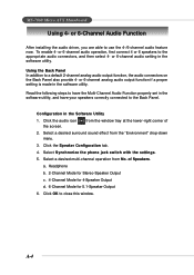
... audio driver, you are able to close this window. or 6-channel audio operation, first connect 4 or 6 speakers to the appropriate audio connectors, and then select 4- Click the Speaker Configuration tab. 4. Select Synchronize the phone jack switch with the settings. 5. Configuration in the software utility, and have your speakers correctly connected to a default 2-channel analog audio output function, the audio connectors on the Back Panel also provide 4- Headphone b. 2-Channel Mode for Stereo-Speaker Output c. 4-Channel Mode for 4-Speaker Output d. 6-Channel Mode for 5.1-Speaker...
... audio driver, you are able to close this window. or 6-channel audio operation, first connect 4 or 6 speakers to the appropriate audio connectors, and then select 4- Click the Speaker Configuration tab. 4. Select Synchronize the phone jack switch with the settings. 5. Configuration in the software utility, and have your speakers correctly connected to a default 2-channel analog audio output function, the audio connectors on the Back Panel also provide 4- Headphone b. 2-Channel Mode for Stereo-Speaker Output c. 4-Channel Mode for 4-Speaker Output d. 6-Channel Mode for 5.1-Speaker...

