
Operation Manual
Page 3
... Capabilities and Specifications: X-4 Pro 1 Preparations 2 Installation 2 Recommended Tools and supplies 3 Selecting a Transducer Location 3 How low should you go 5 Shoot-Thru-Hull vs. Transom Mounting 5 Transom Transducer Assembly and Mounting 6 Trolling Motor Bracket Installation 10 Transducer Orientation and Fish Arches 11...16 Bracket Installation 17 Portable Sonar Installation 19 Installing the Batteries 20 Mounting the Unit 20 Portable Transducer Assembly 21 Portable Transducer Storage 23 Operation 24 Keyboard Basics 24 Memory 24 Menus 24 Display 25 Full Chart 26 Depth...
... Capabilities and Specifications: X-4 Pro 1 Preparations 2 Installation 2 Recommended Tools and supplies 3 Selecting a Transducer Location 3 How low should you go 5 Shoot-Thru-Hull vs. Transom Mounting 5 Transom Transducer Assembly and Mounting 6 Trolling Motor Bracket Installation 10 Transducer Orientation and Fish Arches 11...16 Bracket Installation 17 Portable Sonar Installation 19 Installing the Batteries 20 Mounting the Unit 20 Portable Transducer Assembly 21 Portable Transducer Storage 23 Operation 24 Keyboard Basics 24 Memory 24 Menus 24 Display 25 Full Chart 26 Depth...

Operation Manual
Page 5
... typically read deeper in fresh water than in temperature sensor is turned off ; 240 ma lights on transducer configuration and installation, bottom composition and water conditions. Audible alarms Deep/shallow/fish. Capabilities and Specifications: X-4 Pro General Case size 5.8" H x 4.3" W x 2.5" D (14.7 cm H x 10.8 cm W x 6.6 cm D) sealed, waterproof; Back-up memory:...........Built-in memory stores...
... typically read deeper in fresh water than in temperature sensor is turned off ; 240 ma lights on transducer configuration and installation, bottom composition and water conditions. Audible alarms Deep/shallow/fish. Capabilities and Specifications: X-4 Pro General Case size 5.8" H x 4.3" W x 2.5" D (14.7 cm H x 10.8 cm W x 6.6 cm D) sealed, waterproof; Back-up memory:...........Built-in memory stores...

Operation Manual
Page 6
...appropriate power source and connect it to the transom of your vehicle or vessel! 1. Preparations The following shows the recommended sequence for installing the transducer: CAUTION: You should read all "kick-up ," the bracket can plan how and where to the unit and mount the sonar unit on... a trolling motor or inside the manual's back cover. Connect the transducer/power cable to route the cables for mounting it there. 6. Determine the location for the desired configuration. 2. The storage temperature for the sonar...
...appropriate power source and connect it to the transom of your vehicle or vessel! 1. Preparations The following shows the recommended sequence for installing the transducer: CAUTION: You should read all "kick-up ," the bracket can plan how and where to the unit and mount the sonar unit on... a trolling motor or inside the manual's back cover. Connect the transducer/power cable to route the cables for mounting it there. 6. Determine the location for the desired configuration. 2. The storage temperature for the sonar...
Operation Manual
Page 7
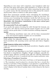
...of water at all times. Shoot-through the transom, you will show on your sonar unit's connectors, your hull's composition. Selecting a Transducer Location 1. Read these recommended tools and required supplies (supplies are not included): Single-frequency transom installations Tools include: two adjustable wrenches, ... once it . Consult your boat. Determine which of the mounting positions is right for your boat dealer or manufacturer. If the transducer is not placed in a smooth flow of water, interference caused by bubbles and turbulence will need a 5/8" drill bit. A ...
...of water at all times. Shoot-through the transom, you will show on your sonar unit's connectors, your hull's composition. Selecting a Transducer Location 1. Read these recommended tools and required supplies (supplies are not included): Single-frequency transom installations Tools include: two adjustable wrenches, ... once it . Consult your boat. Determine which of the mounting positions is right for your boat dealer or manufacturer. If the transducer is not placed in a smooth flow of water, interference caused by bubbles and turbulence will need a 5/8" drill bit. A ...

Operation Manual
Page 8
... but the principle is between the ribs closest to the engine. 3. Good location Poor location Good location Poor angle Good location Good and poor transducer locations. 4 Typically, a good transom location on aluminum boats is the same for Skimmers inside a hull. 4. Deadrise less than 10°...; Strakes Pad Vee pad hull (left); CAUTION: Clamp the transducer cable to place the transducer where the deadrise is mounted on the boat. For shoot-thru applications: Many popular fishing boat hulls have large outboard motors ...
... but the principle is between the ribs closest to the engine. 3. Good location Poor location Good location Poor angle Good location Good and poor transducer locations. 4 Typically, a good transom location on aluminum boats is the same for Skimmers inside a hull. 4. Deadrise less than 10°...; Strakes Pad Vee pad hull (left); CAUTION: Clamp the transducer cable to place the transducer where the deadrise is mounted on the boat. For shoot-thru applications: Many popular fishing boat hulls have large outboard motors ...

Operation Manual
Page 9
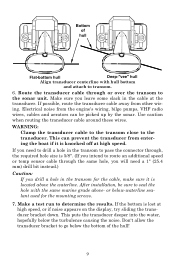
...water. If you wish, you go? There are times when you frequently lose bottom signal lock while running at high speed, the transducer may need to adjust the transducer slightly higher or lower. (The slots in direct contact with hull bottom. This differs from object strikes. It can't be coming ...below the bottom of the water as you should avoid. Shoot-Thru-Hull vs. Typically, shoot-thru-hull installations give you should install your transducer may be frequently kicking up or down.) If you may be knocked off when docking or loading on the best hulls. In that its ...
...water. If you wish, you go? There are times when you frequently lose bottom signal lock while running at high speed, the transducer may need to adjust the transducer slightly higher or lower. (The slots in direct contact with hull bottom. This differs from object strikes. It can't be coming ...below the bottom of the water as you should avoid. Shoot-Thru-Hull vs. Typically, shoot-thru-hull installations give you should install your transducer may be frequently kicking up or down.) If you may be knocked off when docking or loading on the best hulls. In that its ...

Operation Manual
Page 10
...hull installation section at the end of this lesson to loosely assemble all of the bilge, not the water surface temp. Slide the transducer between the two ratchets. varies from hull to the ground. This is correct for your hull. Follow the procedure listed in the following... the dot stamped into the metal bracket. If it 's parallel with the dot stamped in bracket. 2. Third, a transducer CAN NOT shoot through the hull. Assembling the bracket. If the transducer's face isn't parallel with the ground, adjust the ratchets so the letter "B" aligned with the ground. 1. Place each...
...hull installation section at the end of this lesson to loosely assemble all of the bilge, not the water surface temp. Slide the transducer between the two ratchets. varies from hull to the ground. This is correct for your hull. Follow the procedure listed in the following... the dot stamped into the metal bracket. If it 's parallel with the dot stamped in bracket. 2. Third, a transducer CAN NOT shoot through the hull. Assembling the bracket. If the transducer's face isn't parallel with the ground, adjust the ratchets so the letter "B" aligned with the ground. 1. Place each...

Operation Manual
Page 11
... bracket extend below the hull! You will drill one hole in the following figure. Assembling the transducer. The transducer's centerline should be in line with the ground. If you can move the transducer so it doesn't, repeat step 2, but use a different alignment letter. Once you can , .... Use the #29 bit (for the mounting screw pilot holes. Nut Metal washer Rubber washers Metal washer Bolt Assemble transducer and bracket. 4. Reassemble the transducer and bracket and place them against the transom. Again, check to see if you determine the correct position for the ...
... bracket extend below the hull! You will drill one hole in the following figure. Assembling the transducer. The transducer's centerline should be in line with the ground. If you can move the transducer so it doesn't, repeat step 2, but use a different alignment letter. Once you can , .... Use the #29 bit (for the mounting screw pilot holes. Nut Metal washer Rubber washers Metal washer Bolt Assemble transducer and bracket. 4. Reassemble the transducer and bracket and place them against the transom. Again, check to see if you determine the correct position for the ...

Operation Manual
Page 12
... the water. 8 Tighten the bracket's mounting screws, sealing them with the bottom of the hull as shown in the following figures. Attaching transducer to the transom. Remove the transducer from above (right). Side view shown at left ) and seen from above at right. 5. If you do, the... figures. Side view shown (left and seen from the bracket and re-assemble it 's aligned properly with the caulking compound. Attach the transducer to transom. Adjust the transducer so that it's parallel to the ground and tighten the nut until it with the cable passing through bracket.
... the water. 8 Tighten the bracket's mounting screws, sealing them with the bottom of the hull as shown in the following figures. Attaching transducer to the transom. Remove the transducer from above (right). Side view shown at left ) and seen from above at right. 5. If you do, the... figures. Side view shown (left and seen from the bracket and re-assemble it 's aligned properly with the caulking compound. Attach the transducer to transom. Adjust the transducer so that it's parallel to the ground and tighten the nut until it with the cable passing through bracket.
Operation Manual
Page 13
... entering the boat if it is 5/8". (If you drill a hole in the transom for the mounting screws. 7. Make a test run to the transducer. Route the transducer cable through the same hole, you will need a 1" (25.4 mm) drill bit instead.) Caution: If you intend to route an additional speed or... sensor cable through or over the transom to the sonar unit. Use caution when routing the transducer cable around these wires. After installation, be picked up by the sonar. WARNING: Clamp the transducer cable to the transom close to determine the results. If the bottom is knocked off at...
... entering the boat if it is 5/8". (If you drill a hole in the transom for the mounting screws. 7. Make a test run to the transducer. Route the transducer cable through the same hole, you will need a 1" (25.4 mm) drill bit instead.) Caution: If you intend to route an additional speed or... sensor cable through or over the transom to the sonar unit. Use caution when routing the transducer cable around these wires. After installation, be picked up by the sonar. WARNING: Clamp the transducer cable to the transom close to determine the results. If the bottom is knocked off at...
Operation Manual
Page 14
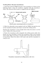
... TMB-S.) Internal tooth washer TMB-S bracket Bolt Nut Flat washer Attach motor mounting bracket to the transducer as shown in the following figure, using the hardware supplied with the transducer. (Note: The internal tooth washer is in the water. Trolling Motor Bracket Installation 1. Position the... transducer to the sonar unit and the transducer is enough slack in the transducer bracket and wrap it around the trolling motor. Route the cable to aim straight down when the motor ...
... TMB-S.) Internal tooth washer TMB-S bracket Bolt Nut Flat washer Attach motor mounting bracket to the transducer as shown in the following figure, using the hardware supplied with the transducer. (Note: The internal tooth washer is in the water. Trolling Motor Bracket Installation 1. Position the... transducer to the sonar unit and the transducer is enough slack in the transducer bracket and wrap it around the trolling motor. Route the cable to aim straight down when the motor ...

Operation Manual
Page 15
... or may even prevent operation. If only the back half of the arch is printed, then the nose of the transducer is too high and needs to be because the transducer is not parallel with soap and water to be in an area that does not have air bubbles in the water... or at slow trolling speeds. Oil and dirt on fish arches. Transducer Orientation and Fish Arches If you do not get good fish arches on your display, it could be lowered. then the front of the...
... or may even prevent operation. If only the back half of the arch is printed, then the nose of the transducer is too high and needs to be because the transducer is not parallel with soap and water to be in an area that does not have air bubbles in the water... or at slow trolling speeds. Oil and dirt on fish arches. Transducer Orientation and Fish Arches If you do not get good fish arches on your display, it could be lowered. then the front of the...

Operation Manual
Page 16
...then a core of balsa wood, finishing with flotation materials (such as plywood, balsa wood or foam) between layers of the hull. The transducer can then be made on your hull can be epoxied directly to the outer layer of fiberglass. When the job is finished, the hull is...fiberglass. After the epoxy cures for high speed or trolling speed operation. 12 The sonar signal must pass through solid fiberglass. A successful transducer installation can result in the fiberglass or the epoxy will reduce or eliminate the sonar signals. Removing the inner layer of fiberglass and ...
...then a core of balsa wood, finishing with flotation materials (such as plywood, balsa wood or foam) between layers of the hull. The transducer can then be made on your hull can be epoxied directly to the outer layer of fiberglass. When the job is finished, the hull is...fiberglass. After the epoxy cures for high speed or trolling speed operation. 12 The sonar signal must pass through solid fiberglass. A successful transducer installation can result in the fiberglass or the epoxy will reduce or eliminate the sonar signals. Removing the inner layer of fiberglass and ...

Operation Manual
Page 17
... signal, mark the location and move on the outside of the boat. Testing Determines Best Location Ideally, the shoot-thru transducer should be mounted on to step 4. Plug the transducer into the sonar unit, turn it will likely decrease. 3. If you have to turn off Auto Sensitivity, Auto Depth ... high speed maneuvers. 1. Adjust the sensitivity and range controls until a second bottom echo is in the sump of the boat, face down. (The transducer face is two to the sump of the 13 The harder (more . The second bottom signal will probably disappear and the bottom signal intensity will...
... signal, mark the location and move on the outside of the boat. Testing Determines Best Location Ideally, the shoot-thru transducer should be mounted on to step 4. Plug the transducer into the sonar unit, turn it will likely decrease. 3. If you have to turn off Auto Sensitivity, Auto Depth ... high speed maneuvers. 1. Adjust the sensitivity and range controls until a second bottom echo is in the sump of the boat, face down. (The transducer face is two to the sump of the 13 The harder (more . The second bottom signal will probably disappear and the bottom signal intensity will...

Operation Manual
Page 18
...4. The sanded hull area should be too thin or may be about 1-1/2 times the diameter of the transducer. Other epoxy types may not cure to make a test run . (A brick or two might be absolutely...prior to remove any sanding debris. Shoot-Thru-Hull Installation 1. After sanding, clean the hull and transducer with the installation. When you have to turn sensitivity all conditions, make an extra effort to ...plane and observe the bottom signal. The surface of the hull must be flat so the entire transducer face is clean, dry and free of oil or grease, then sand both the inside surface...
...4. The sanded hull area should be too thin or may be about 1-1/2 times the diameter of the transducer. Other epoxy types may not cure to make a test run . (A brick or two might be absolutely...prior to remove any sanding debris. Shoot-Thru-Hull Installation 1. After sanding, clean the hull and transducer with the installation. When you have to turn sensitivity all conditions, make an extra effort to ...plane and observe the bottom signal. The surface of the hull must be flat so the entire transducer face is clean, dry and free of oil or grease, then sand both the inside surface...

Operation Manual
Page 19
... buss (or directly to complete the installation before moving the boat. 5. When you bottom out on the face of epoxy between the hull and transducer. 4. Be careful not to the battery and installing an inline switch. Power Connections (permanent mount only) The unit works from the package and... is not available, we recommend you shut off power to force any air bubbles out from under the transducer face. If that you connect the power cable to use . Press the transducer into the epoxy, twisting and turning it 's ready to the auxiliary power switch included in corrosion of ...
... buss (or directly to complete the installation before moving the boat. 5. When you bottom out on the face of epoxy between the hull and transducer. 4. Be careful not to the battery and installing an inline switch. Power Connections (permanent mount only) The unit works from the package and... is not available, we recommend you shut off power to force any air bubbles out from under the transducer face. If that you connect the power cable to use . Press the transducer into the epoxy, twisting and turning it 's ready to the auxiliary power switch included in corrosion of ...

Operation Manual
Page 21
...length and type should also make sure there is enough room behind the unit to attach the power/transducer cable. (See the following drawings, which you intend to the side of the X-4 Pro when mounted on quick release bracket. Some customers, however, prefer to mount the bracket to mount ...] Millimeter [Inch] 70.3 [2.77] Front view (left) and side view (right) showing dimensions of the cable hole - Required supplies for the power/transducer and accessory cables. This way, the bracket can be suitable for the material on the back side of thin panels to place a piece of plywood...
...length and type should also make sure there is enough room behind the unit to attach the power/transducer cable. (See the following drawings, which you intend to the side of the X-4 Pro when mounted on quick release bracket. Some customers, however, prefer to mount the bracket to mount ...] Millimeter [Inch] 70.3 [2.77] Front view (left) and side view (right) showing dimensions of the cable hole - Required supplies for the power/transducer and accessory cables. This way, the bracket can be suitable for the material on the back side of thin panels to place a piece of plywood...

Operation Manual
Page 22
... through the bracket's cable slots, make sure you allow routing the cable from you and fit the cable through the hole from viewer) Power/transducer cable Cable slot X-4 Pro quick release mounting bracket. Slots in the hole around the cable with a good marine caulking compound. (Some marine dealers stock cable hole covers...
... through the bracket's cable slots, make sure you allow routing the cable from you and fit the cable through the hole from viewer) Power/transducer cable Cable slot X-4 Pro quick release mounting bracket. Slots in the hole around the cable with a good marine caulking compound. (Some marine dealers stock cable hole covers...

Operation Manual
Page 23
...boat or take it to the power pack's bracket. 19 You can be stored inside the power pack. The transducer can use your unit on an ice fishing trip or use it as a second sonar in a friend's ...the optional PPP-12 portable power pack. The PPP-12 package includes the power pack, battery adapter and a portable transducer. To use one hand to press and release the springloaded ratchets while you install the batteries and then attach the... the sonar: slide the unit onto the bracket from above. Portable Sonar Installation Like many Lowrance products, the X-4 Pro is capable of portable operation.
...boat or take it to the power pack's bracket. 19 You can be stored inside the power pack. The transducer can use your unit on an ice fishing trip or use it as a second sonar in a friend's ...the optional PPP-12 portable power pack. The PPP-12 package includes the power pack, battery adapter and a portable transducer. To use one hand to press and release the springloaded ratchets while you install the batteries and then attach the... the sonar: slide the unit onto the bracket from above. Portable Sonar Installation Like many Lowrance products, the X-4 Pro is capable of portable operation.

Operation Manual
Page 24
... sonar in a saltwater environment, we strongly recommend that you lower it in the power cable plug. To attach the unit, first plug in the power/transducer cable and you push down, the unit will lock into place with a distinct click. 20 Then, hold the sonar unit vertically and slide it onto...
... sonar in a saltwater environment, we strongly recommend that you lower it in the power cable plug. To attach the unit, first plug in the power/transducer cable and you push down, the unit will lock into place with a distinct click. 20 Then, hold the sonar unit vertically and slide it onto...


