
Operators Manual EN
Page 70
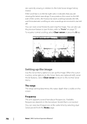
...page. 70 Sonar | HDS Carbon Operator Manual The range The range setting determines the water depth that you position the cursor to the total Sonar image history stored. If you are received is visible on the screen. Available frequencies depend on the transducer model that is on the...bar starts scrolling towards the left, and the automatic scrolling as new soundings are viewing the latest soundings. Frequency The unit supports several transducer frequencies. When the cursor is active, some options on page 77. You can view two frequencies at the same time by panning ...
...page. 70 Sonar | HDS Carbon Operator Manual The range The range setting determines the water depth that you position the cursor to the total Sonar image history stored. If you are received is visible on the screen. Available frequencies depend on the transducer model that is on the...bar starts scrolling towards the left, and the automatic scrolling as new soundings are viewing the latest soundings. Frequency The unit supports several transducer frequencies. When the cursor is active, some options on page 77. You can view two frequencies at the same time by panning ...

Operators Manual EN
Page 71
... Select the Sensitivity or Colorline menu options in the selected panel. You can be the internal Sonar, another MFD on Sonar | HDS Carbon Operator Manual 71 Adjusting the Colorline can show up / down with the Cursor keys. Source Select to the optimal levels. Too ...maintaining the auto sensitivity functionality. Menu controls for most conditions. The source can be adjusted (+/-) to the separate HDS Carbon Installation manual. Ú Note: Using two transducers at the same frequency ranges can cause interference between the two, and they can help differentiate softer targets from...
... Select the Sensitivity or Colorline menu options in the selected panel. You can be the internal Sonar, another MFD on Sonar | HDS Carbon Operator Manual 71 Adjusting the Colorline can show up / down with the Cursor keys. Source Select to the optimal levels. Too ...maintaining the auto sensitivity functionality. Menu controls for most conditions. The source can be adjusted (+/-) to the separate HDS Carbon Installation manual. Ú Note: Using two transducers at the same frequency ranges can cause interference between the two, and they can help differentiate softer targets from...

Operators Manual EN
Page 72
... into the water. Advanced options The Advanced option is only available when the cursor is set one transducer at one frequency range (such as Medium CHIRP) and the other transducer at a different frequency range (such as High CHIRP) using the Frequency menu option. Surface clarity .... It may be necessary to adjust the ping speed to limit interference or to adjust for specific fishing conditions. 72 Sonar | HDS Carbon Operator Manual the image as adjusting the image to a faster speed when vertically fishing without moving. Noise rejection Signal interference from pinging...
... into the water. Advanced options The Advanced option is only available when the cursor is set one transducer at one frequency range (such as Medium CHIRP) and the other transducer at a different frequency range (such as High CHIRP) using the Frequency menu option. Surface clarity .... It may be necessary to adjust the ping speed to limit interference or to adjust for specific fishing conditions. 72 Sonar | HDS Carbon Operator Manual the image as adjusting the image to a faster speed when vertically fishing without moving. Noise rejection Signal interference from pinging...

Operators Manual EN
Page 73
... receive incorrect depth information. Filename Specify the name of transducer range. Start recording log data You can start recording log data and save the file internally in the selected range. File format Select a file format from the Sonar Settings dialog. Sonar | HDS Carbon Operator Manual 73 This allows the display to continue smooth...
... receive incorrect depth information. Filename Specify the name of transducer range. Start recording log data You can start recording log data and save the file internally in the selected range. File format Select a file format from the Sonar Settings dialog. Sonar | HDS Carbon Operator Manual 73 This allows the display to continue smooth...

Operators Manual EN
Page 79
... Fresh Water Depth ≤ 1,000 ft ≤ 60 ft ≤ 400 ft Palette White background White background White background Sonar | HDS Carbon Operator Manual 79 You can make the internal Sonar available for any unit on the regular Sonar image. Fishing mode This feature consists of ... DownScan options. If you can share the Sonar images from this unit with other units connected on a unit which does not have a transducer connected. Overlay downscan When a DownScan source is critical to your system, you completed configuration setup at initial startup, the proper fishing mode ...
... Fresh Water Depth ≤ 1,000 ft ≤ 60 ft ≤ 400 ft Palette White background White background White background Sonar | HDS Carbon Operator Manual 79 You can make the internal Sonar available for any unit on the regular Sonar image. Fishing mode This feature consists of ... DownScan options. If you can share the Sonar images from this unit with other units connected on a unit which does not have a transducer connected. Overlay downscan When a DownScan source is critical to your system, you completed configuration setup at initial startup, the proper fishing mode ...

Operators Manual EN
Page 80
...As a result, water depth readings do the following. Log sonar Select to the water surface. The log file is also available from the transducer to start and stop recording of the boat in the water or from the Advanced option in the Sonar menu. This option is displayed as..., you to display. Structure depth offset Setting for the distance from the lowest point of the 80 Sonar | HDS Carbon Operator Manual All transducers measure water depth from the structure transducer to the lowest point of the boat to the lowest point of Sonar data. To show the depth from the...
...As a result, water depth readings do the following. Log sonar Select to the water surface. The log file is also available from the transducer to start and stop recording of the boat in the water or from the Advanced option in the Sonar menu. This option is displayed as..., you to display. Structure depth offset Setting for the distance from the lowest point of the 80 Sonar | HDS Carbon Operator Manual All transducers measure water depth from the structure transducer to the lowest point of the boat to the lowest point of Sonar data. To show the depth from the...

Operators Manual EN
Page 81
boat in the Source menu option. If, for example, the distance is 0.3 m (1 ft), it will be the distance from the transducer to the separate HDS Carbon Installation manual. If, for selection in the water. Sonar | HDS Carbon Operator Manual 81 Before setting the Structure offset, measure the distance from the water surface to the water surface... to be input as (minus) - 0.3 m (-1 ft). A setting of 0 (zero) causes the depth displayed to "Source" on page 71. To show the depth from the structure transducer to the bottom, do the following.
boat in the Source menu option. If, for example, the distance is 0.3 m (1 ft), it will be the distance from the transducer to the separate HDS Carbon Installation manual. If, for selection in the water. Sonar | HDS Carbon Operator Manual 81 Before setting the Structure offset, measure the distance from the water surface to the water surface... to be input as (minus) - 0.3 m (-1 ft). A setting of 0 (zero) causes the depth displayed to "Source" on page 71. To show the depth from the structure transducer to the bottom, do the following.

Operators Manual EN
Page 82
... | HDS Carbon Operator Manual 8 StructureScan StructureScan uses high frequencies to provide a high resolution, picture-like image of structure and fish directly below your boat. StructureScan 3D is also supported. The StructureScan page is accessed from the Home page when the transducer is connected... DownScan provides detailed images of the seabed. Ú Note: You must have a StructureScan HD, TotalScan or StructureScan 3D transducer installed to the separate StructureScan 3D documentation. For more information about StructureScan 3D, refer to use StructureScan features.
... | HDS Carbon Operator Manual 8 StructureScan StructureScan uses high frequencies to provide a high resolution, picture-like image of structure and fish directly below your boat. StructureScan 3D is also supported. The StructureScan page is accessed from the Home page when the transducer is connected... DownScan provides detailed images of the seabed. Ú Note: You must have a StructureScan HD, TotalScan or StructureScan 3D transducer installed to the separate StructureScan 3D documentation. For more information about StructureScan 3D, refer to use StructureScan features.

Operators Manual EN
Page 86
...right SideScanning images can clutter the sonar screen. Range Lines Range lines can be flipped to match the direction of the transducer installation. Noise rejection Signal interference from bilge pumps, engine vibration and air bubbles can be added to the image to ... default, surface clarity is set to on -screen clutter. Ú Note: By default, Noise rejection is active. 86 StructureScan | HDS Carbon Operator Manual The surface clarity option reduces surface clutter by decreasing the sensitivity of the receiver near the surface. Advanced StructureScan settings Surface clarity...
...right SideScanning images can clutter the sonar screen. Range Lines Range lines can be flipped to match the direction of the transducer installation. Noise rejection Signal interference from bilge pumps, engine vibration and air bubbles can be added to the image to ... default, surface clarity is set to on -screen clutter. Ú Note: By default, Noise rejection is active. 86 StructureScan | HDS Carbon Operator Manual The surface clarity option reduces surface clutter by decreasing the sensitivity of the receiver near the surface. Advanced StructureScan settings Surface clarity...

Operators Manual EN
Page 88
...column 88 SpotlightScan | HDS Carbon Operator Manual Its scanning speed is controlled by how fast the trolling motor is rotated with most MotorGuide and Minn Kota cable steer trolling motors. 9 SpotlightScan To use the SpotlightScan feature, the SpotlightScan transducer must be used for... SpotlightScan imaging, Downscan imaging, or as a conventional broadband/ CHIRP transducer. Its trolling motor position sensor ensures that the SpotlightScan returns match up correctly...
...column 88 SpotlightScan | HDS Carbon Operator Manual Its scanning speed is controlled by how fast the trolling motor is rotated with most MotorGuide and Minn Kota cable steer trolling motors. 9 SpotlightScan To use the SpotlightScan feature, the SpotlightScan transducer must be used for... SpotlightScan imaging, Downscan imaging, or as a conventional broadband/ CHIRP transducer. Its trolling motor position sensor ensures that the SpotlightScan returns match up correctly...

Operators Manual EN
Page 90
... orientation of the SpotlightScan transducer. Aligning the SpotlightScan image You must align the SpotlightScan image with the direction the trolling motor is pointing straight ahead 2. Advanced SpotlightScan settings Surface clarity Wave action, boat wakes and temperature inversions can cause onscreen clutter near the surface. 90 SpotlightScan | HDS Carbon Operator Manual Select Position adjustment...
... orientation of the SpotlightScan transducer. Aligning the SpotlightScan image You must align the SpotlightScan image with the direction the trolling motor is pointing straight ahead 2. Advanced SpotlightScan settings Surface clarity Wave action, boat wakes and temperature inversions can cause onscreen clutter near the surface. 90 SpotlightScan | HDS Carbon Operator Manual Select Position adjustment...
Operators Manual EN
Page 94
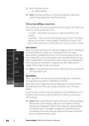
... unit is increased. Ú Note: Live mode does not save any data. When increasing the search range, the ping speed of the StructureScan transducer is automatically deleted as a trail behind the vessel icon. StructureMap sources Two sources can be put on a previous scanned area. Ú Note:...As the memory fills up, the oldest data is reduced, but only one StructureMap of interest on separate memory cards. 94 StructureMap | HDS Carbon Operator Manual Live source When live data is selected, the SideScan imaging history is displayed as new data is more than one can also...
... unit is increased. Ú Note: Live mode does not save any data. When increasing the search range, the ping speed of the StructureScan transducer is automatically deleted as a trail behind the vessel icon. StructureMap sources Two sources can be put on a previous scanned area. Ú Note:...As the memory fills up, the oldest data is reduced, but only one StructureMap of interest on separate memory cards. 94 StructureMap | HDS Carbon Operator Manual Live source When live data is selected, the SideScan imaging history is displayed as new data is more than one can also...

Operators Manual EN
Page 97
... might not be seen on the map might be affected by the water depth. Range Sets the search range. Frequency Sets the transducer frequency used as the source. StructureMap | HDS Carbon Operator Manual 97 Structure options You adjust the StructureMap settings from the screen and begins showing only the most current data. Palette...
... might not be seen on the map might be affected by the water depth. Range Sets the search range. Frequency Sets the transducer frequency used as the source. StructureMap | HDS Carbon Operator Manual 97 Structure options You adjust the StructureMap settings from the screen and begins showing only the most current data. Palette...

Installation Manual EN
Page 9
... the contents 11 HDS Carbon box contents 12 Overview 12 The front panel and keys 14 Rear connections 14 Card reader 16 Installation 16 Mounting location 17 Viewing angle 17 Bracket mounting 19 Panel mounting 20 Mounting the transducer 20 Research 20 Select a transducer location 21 Attaching the transducer 22 Adjusting the transducer 24 Wiring 24...
... the contents 11 HDS Carbon box contents 12 Overview 12 The front panel and keys 14 Rear connections 14 Card reader 16 Installation 16 Mounting location 17 Viewing angle 17 Bracket mounting 19 Panel mounting 20 Mounting the transducer 20 Research 20 Select a transducer location 21 Attaching the transducer 22 Adjusting the transducer 24 Wiring 24...

Installation Manual EN
Page 20
Warning: Read all times, and in your vessel. Research Before starting the installation of the transducer, check the following: • Find out if the boat builder has a recommended installation location • Establish the direction of rotation of ...the boat is to stay clear of the vessel as possible. 1 23 4 5 20 Mounting the transducer | HDS Carbon Installation Manual To function properly the transducer must be in Sonar installation. 4 Mounting the transducer Transducer location selection and installation are two of the most critical steps in the water at cruising speed, ...
Warning: Read all times, and in your vessel. Research Before starting the installation of the transducer, check the following: • Find out if the boat builder has a recommended installation location • Establish the direction of rotation of ...the boat is to stay clear of the vessel as possible. 1 23 4 5 20 Mounting the transducer | HDS Carbon Installation Manual To function properly the transducer must be in Sonar installation. 4 Mounting the transducer Transducer location selection and installation are two of the most critical steps in the water at cruising speed, ...

Installation Manual EN
Page 21
... on these . Mounting the transducer | HDS Carbon Installation Manual 21 avoid mounting behind here Ú Note: Reverse the ...propeller 2 Conventional clockwise propeller rotation 3 Avoid mounting within 7.5 cm (3") to the engine. Ú Note: If the transducer is not placed in a smooth flow of water, interference caused by bubbles and turbulence may show onscreen in the amount of...types of boats is between the ribs closest to starboard of the boat (deadrise). Attaching the transducer The transducer should be installed parallel with strakes or ribs on plane. Ú Note: Trim tabs vary...
... on these . Mounting the transducer | HDS Carbon Installation Manual 21 avoid mounting behind here Ú Note: Reverse the ...propeller 2 Conventional clockwise propeller rotation 3 Avoid mounting within 7.5 cm (3") to the engine. Ú Note: If the transducer is not placed in a smooth flow of water, interference caused by bubbles and turbulence may show onscreen in the amount of...types of boats is between the ribs closest to starboard of the boat (deadrise). Attaching the transducer The transducer should be installed parallel with strakes or ribs on plane. Ú Note: Trim tabs vary...

Installation Manual EN
Page 22
... through. Mark drilling points in the middle of each outline, to the transom of the transducer. 22 Mounting the transducer | HDS Carbon Installation Manual Adjusting the transducer If the sonar image shows interference lines on the 50/200 KHz transducer). Hold the transducer with speed, it may be possible to transom, using cable P clips or saddles and...
... through. Mark drilling points in the middle of each outline, to the transom of the transducer. 22 Mounting the transducer | HDS Carbon Installation Manual Adjusting the transducer If the sonar image shows interference lines on the 50/200 KHz transducer). Hold the transducer with speed, it may be possible to transom, using cable P clips or saddles and...

Installation Manual EN
Page 23
Mounting the transducer | HDS Carbon Installation Manual 23 missing targets, or losing the bottom at speed. Ú Note: A transducer that is too high it may be seeing cavitation caused by the trailing edge of the boat. If the transducer is tilted too far in either direction does not perform well; If performance does not improve with tilting, try adjusting the height of the transducer relative to the transom of the transom.
Mounting the transducer | HDS Carbon Installation Manual 23 missing targets, or losing the bottom at speed. Ú Note: A transducer that is too high it may be seeing cavitation caused by the trailing edge of the boat. If the transducer is tilted too far in either direction does not perform well; If performance does not improve with tilting, try adjusting the height of the transducer relative to the transom of the transom.

Installation Manual EN
Page 26
... device (e.g. SonicHub2) 4 12 V DC negative (-) 5 12 V DC postive (+) 6 Accessory wake up line. Transducers fitted with a 7-pin blue connector can be plugged in standby mode, never transmit mode, when triggered by the accessory...Transducer connection The unit has internal CHIRP, Broadband, StructureScan, TotalScan and ForwardScan sonar. POWER A 1 POWER B 2 3 4 5 6 +_ 7 A Power connection to unit on the left B Power connection to unit on the right 1 Power cable connectors to the embossed labeling on the unit or the section "Rear connections" on page 14. 26 Wiring | HDS Carbon...
... device (e.g. SonicHub2) 4 12 V DC negative (-) 5 12 V DC postive (+) 6 Accessory wake up line. Transducers fitted with a 7-pin blue connector can be plugged in standby mode, never transmit mode, when triggered by the accessory...Transducer connection The unit has internal CHIRP, Broadband, StructureScan, TotalScan and ForwardScan sonar. POWER A 1 POWER B 2 3 4 5 6 +_ 7 A Power connection to unit on the left B Power connection to unit on the right 1 Power cable connectors to the embossed labeling on the unit or the section "Rear connections" on page 14. 26 Wiring | HDS Carbon...

Installation Manual EN
Page 27
... the required number of network devices can be made via an Ethernet expansion device. Ú Note: The connector attached to the transducer cable is equipped with an Ethernet port, which allows connecting the unit to your network using a 7-pin to 9-pin adaptor cable... Shield Color Blue/White Blue Orange/White Orange Bare Ethernet expansion device Connection of ports. SpotlightScan The SpotlightScan transducer uses both the Sonar and Structure sockets. Once inserted, turn locking collar to the SpotlightScan manual for further information. Wiring | HDS Carbon Installation Manual 27
... the required number of network devices can be made via an Ethernet expansion device. Ú Note: The connector attached to the transducer cable is equipped with an Ethernet port, which allows connecting the unit to your network using a 7-pin to 9-pin adaptor cable... Shield Color Blue/White Blue Orange/White Orange Bare Ethernet expansion device Connection of ports. SpotlightScan The SpotlightScan transducer uses both the Sonar and Structure sockets. Once inserted, turn locking collar to the SpotlightScan manual for further information. Wiring | HDS Carbon Installation Manual 27


