
HALO 20 20 and 24 Installation Manual
Page 1
Halo20, 20+ and 24 Dome Radars Installation Manual ENGLISH www.lowrance.com www.simrad-yachting.com www.bandg.com
Halo20, 20+ and 24 Dome Radars Installation Manual ENGLISH www.lowrance.com www.simrad-yachting.com www.bandg.com
HALO 20 20 and 24 Installation Manual
Page 3
...the product at any further assistance. RF emissions notice This equipment complies with provided instructions, and it must Preface | Halo20, 20+ and 24 Dome Radars Installation Manual | 3 The user of the Documentation. NAVICO HOLDING AS AND ITS SUBSIDIARIES, BRANCHES AND AFFILIATES DISCLAIM ALL LIABILITY ...relevant Declaration of conformity is continuously improving this product, we retain the right to make changes to the following websites: www.lowrance.com www.simrad-yachting.com www.bandg.com United States of America Part 15 of printing. Preface Disclaimer As Navico is ...
...the product at any further assistance. RF emissions notice This equipment complies with provided instructions, and it must Preface | Halo20, 20+ and 24 Dome Radars Installation Manual | 3 The user of the Documentation. NAVICO HOLDING AS AND ITS SUBSIDIARIES, BRANCHES AND AFFILIATES DISCLAIM ALL LIABILITY ...relevant Declaration of conformity is continuously improving this product, we retain the right to make changes to the following websites: www.lowrance.com www.simrad-yachting.com www.bandg.com United States of America Part 15 of printing. Preface Disclaimer As Navico is ...
HALO 20 20 and 24 Installation Manual
Page 4
...érieur au gain maximal indiqué, sont strictement interdits pour l'exploitation de l'émetteur. 4 | Preface | Halo20, 20+ and 24 Dome Radars Installation Manual Le présent appareil est conforme aux CNR d'Industrie Canada applicables aux appareils radio exempts de licence. This radio... all person's body (excluding extremities of the FCC Rules. be operated with minimum 0.1 m (0.33 ft) for Halo20+ and Halo24, and 0.0 m (0.0 ft) for Halo20 spacing between the equipment and receiver • Connect the equipment into an outlet on , the user is connected •...
...érieur au gain maximal indiqué, sont strictement interdits pour l'exploitation de l'émetteur. 4 | Preface | Halo20, 20+ and 24 Dome Radars Installation Manual Le présent appareil est conforme aux CNR d'Industrie Canada applicables aux appareils radio exempts de licence. This radio... all person's body (excluding extremities of the FCC Rules. be operated with minimum 0.1 m (0.33 ft) for Halo20+ and Halo24, and 0.0 m (0.0 ft) for Halo20 spacing between the equipment and receiver • Connect the equipment into an outlet on , the user is connected •...
HALO 20 20 and 24 Installation Manual
Page 5
...independent laboratory. About this manual This manual is a registered trademark of injury and/or damage to equipment/personnel. Lowrance® is a reference guide for installing the Halo dome radar. Important text that they... should proceed carefully to prevent risk of Navico Holding AS. Warning: Used when it is emphasized as measured by license from the reader is necessary to a comment or some important information. ! Halo Antennas Halo 20 Radar Halo20+ Radar Halo24 Radar...
...independent laboratory. About this manual This manual is a registered trademark of injury and/or damage to equipment/personnel. Lowrance® is a reference guide for installing the Halo dome radar. Important text that they... should proceed carefully to prevent risk of Navico Holding AS. Warning: Used when it is emphasized as measured by license from the reader is necessary to a comment or some important information. ! Halo Antennas Halo 20 Radar Halo20+ Radar Halo24 Radar...
HALO 20 20 and 24 Installation Manual
Page 6
... Preface 3 Disclaimer 3 Copyright 3 Warranty 3 Compliance statement 5 Radio Frequency (RF) Exposure table 5 Trademarks 5 About this manual 7 Introduction 7 Parts included 8 Installation 8 Wiring guidelines 9 Choose the scanner location 10 Considerations for roof mounting 13 Wiring ...3G/4G Radar 22 RI-10 Radar interface box and wiring 23 Troubleshooting 23 Status LED 23 Error messages 24 Error codes 25 Dimensional drawings 25 Halo dome radar dimensions 27 Technical specifications 27 Halo20/20+ Radar 28 Halo24 Radar 29 Accessories 6 | Contents | Halo20, 20+ and 24 Dome Radars Installation Manual
... Preface 3 Disclaimer 3 Copyright 3 Warranty 3 Compliance statement 5 Radio Frequency (RF) Exposure table 5 Trademarks 5 About this manual 7 Introduction 7 Parts included 8 Installation 8 Wiring guidelines 9 Choose the scanner location 10 Considerations for roof mounting 13 Wiring ...3G/4G Radar 22 RI-10 Radar interface box and wiring 23 Troubleshooting 23 Status LED 23 Error messages 24 Error codes 25 Dimensional drawings 25 Halo dome radar dimensions 27 Technical specifications 27 Halo20/20+ Radar 28 Halo24 Radar 29 Accessories 6 | Contents | Halo20, 20+ and 24 Dome Radars Installation Manual
HALO 20 20 and 24 Installation Manual
Page 7
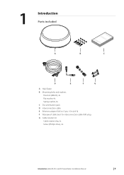
1 Introduction Parts included A B bbbbaaaannnnddddgggg....ccccoooommmm EEEENNNNGGGGLLLLIIIISSSSHHHHIIIInnnnssssttttaaaallllllllaaaattttiiiioooonnnn MMMMaaaannnnuuuuaaaallll C D E F G A Halo Radar B Mounting bolts and washers Hex bolt (M8x30), 4x Flat washer, 4x Spring washer, 4x C Documentation pack D Interconnection cable E Ethernet adapter RJ45 to 5-pin, 1.5m (4.9 ft) F Waterproof cable boot for interconnection cable RJ45 plug G Cable retainer kit Cable retainer clip, 2x Screw (Phillips drive), 4x Introduction | Halo20, 20+ and 24 Dome Radars Installation Manual | 7
1 Introduction Parts included A B bbbbaaaannnnddddgggg....ccccoooommmm EEEENNNNGGGGLLLLIIIISSSSHHHHIIIInnnnssssttttaaaallllllllaaaattttiiiioooonnnn MMMMaaaannnnuuuuaaaallll C D E F G A Halo Radar B Mounting bolts and washers Hex bolt (M8x30), 4x Flat washer, 4x Spring washer, 4x C Documentation pack D Interconnection cable E Ethernet adapter RJ45 to 5-pin, 1.5m (4.9 ft) F Waterproof cable boot for interconnection cable RJ45 plug G Cable retainer kit Cable retainer clip, 2x Screw (Phillips drive), 4x Introduction | Halo20, 20+ and 24 Dome Radars Installation Manual | 7
HALO 20 20 and 24 Installation Manual
Page 8
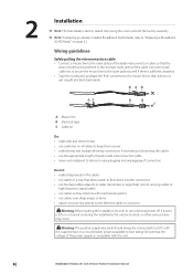
...or a circuit breaker (closest available to the stronger outer jacket of the power supply is compatible with the unit. 8 | Installation | Halo20, 20+ and 24 Dome Radars Installation Manual BAB AC B B A Mouse line B Electrical tape C Cable tie Do: • make drip and service loops... to fuse rating). Wiring guidelines Safely pulling the interconnection cable • Connect a mouse line to the outer jacket of the radar interconnection cable so that the strain of pulling is sufficient clearance. • Tape the conductors and tape the RJ45 connector to ...
...or a circuit breaker (closest available to the stronger outer jacket of the power supply is compatible with the unit. 8 | Installation | Halo20, 20+ and 24 Dome Radars Installation Manual BAB AC B B A Mouse line B Electrical tape C Cable tie Do: • make drip and service loops... to fuse rating). Wiring guidelines Safely pulling the interconnection cable • Connect a mouse line to the outer jacket of the radar interconnection cable so that the strain of pulling is sufficient clearance. • Tape the conductors and tape the RJ45 connector to ...
HALO 20 20 and 24 Installation Manual
Page 9
...the minimum range around the vessel where targets cannot be detected. Installation | Halo20, 20+ and 24 Dome Radars Installation Manual | 9 If you think you'll need a longer cable, consult your radar is not installed in the beam of a pulse radar at the top of a mast), which may cause degradation of the... radar picture over short ranges • close to the antennas of the keel....
...the minimum range around the vessel where targets cannot be detected. Installation | Halo20, 20+ and 24 Dome Radars Installation Manual | 9 If you think you'll need a longer cable, consult your radar is not installed in the beam of a pulse radar at the top of a mast), which may cause degradation of the... radar picture over short ranges • close to the antennas of the keel....
HALO 20 20 and 24 Installation Manual
Page 10
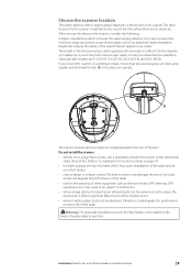
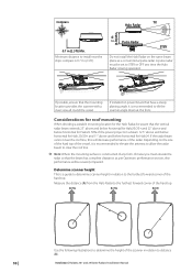
...the ships compass is recommended to STBY or OFF any form of the vessel, it is 0.7 m (2.3 ft). Installation | Halo20, 20+ and 24 Dome Radars Installation Manual If installed on the same beam plane as per Optimum performance section, else performance will decrease performance of the hard top. ... following illustrations to determine the height of the hard top. If the radar beam cannot clear the roof line, this will be aware that the vertical radar beam extends 25° above and below horizontal for Halo20/20+ and 22° above and below horizontal for Halo24. 50%...
...the ships compass is recommended to STBY or OFF any form of the vessel, it is 0.7 m (2.3 ft). Installation | Halo20, 20+ and 24 Dome Radars Installation Manual If installed on the same beam plane as per Optimum performance section, else performance will decrease performance of the hard top. ... following illustrations to determine the height of the hard top. If the radar beam cannot clear the roof line, this will be aware that the vertical radar beam extends 25° above and below horizontal for Halo20/20+ and 22° above and below horizontal for Halo24. 50%...
HALO 20 20 and 24 Installation Manual
Page 11
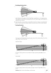
Possible performance loss 50% of beam power 50% of dimension (A), increase the height (B) by 40 mm (1.57"). Halo20/20+ Radar 3.0 m2.80 m2.60 m2.40 m2.20 m2.00 m1.80 m1.60 m1.40 m1.20 m1.00 m0.80 m 0.55 m A 0 mm 60 ... top. ¼ Note: Where the mounting surface is constructed of any form of dimension (A), increase the height (B) by 45 mm (1.77"). Installation | Halo20, 20+ and 24 Dome Radars Installation Manual | 11 Good performance 12.5° 11° The image above illustrates that the beam has complete clearance, else performance will be severely impaired.
Possible performance loss 50% of beam power 50% of dimension (A), increase the height (B) by 40 mm (1.57"). Halo20/20+ Radar 3.0 m2.80 m2.60 m2.40 m2.20 m2.00 m1.80 m1.60 m1.40 m1.20 m1.00 m0.80 m 0.55 m A 0 mm 60 ... top. ¼ Note: Where the mounting surface is constructed of any form of dimension (A), increase the height (B) by 45 mm (1.77"). Installation | Halo20, 20+ and 24 Dome Radars Installation Manual | 11 Good performance 12.5° 11° The image above illustrates that the beam has complete clearance, else performance will be severely impaired.

HALO 20 20 and 24 Installation Manual
Page 12
Halo20/20+ Radar 25° 0.25 m 0.40 m 0.80 m 1.00 m 1.20 m 1.40 m 1.60 m 1.80 m 2.00 m 2.20 m 2.40 m 2.60 ... mm 1280 mm B For every increase of 200 mm (7.87") of dimension (A), increase the height (B) by 80 mm (3.14"). 12 | Installation | Halo20, 20+ and 24 Dome Radars Installation Manual Halo24 Radar 22° 0.38 m 0.60 m 0.80 m 1.00 m 1.20 m 1.40 m 1.60 m 1.80 m 2.00 m 2.20 m ... of 200 mm (7.87") of the boat. Optimum performance For best performance, the radar should be positioned to allow the full beam to clear the superstructure of dimension (A), increase the height (B) by...
Halo20/20+ Radar 25° 0.25 m 0.40 m 0.80 m 1.00 m 1.20 m 1.40 m 1.60 m 1.80 m 2.00 m 2.20 m 2.40 m 2.60 ... mm 1280 mm B For every increase of 200 mm (7.87") of dimension (A), increase the height (B) by 80 mm (3.14"). 12 | Installation | Halo20, 20+ and 24 Dome Radars Installation Manual Halo24 Radar 22° 0.38 m 0.60 m 0.80 m 1.00 m 1.20 m 1.40 m 1.60 m 1.80 m 2.00 m 2.20 m ... of 200 mm (7.87") of the boat. Optimum performance For best performance, the radar should be positioned to allow the full beam to clear the superstructure of dimension (A), increase the height (B) by...
HALO 20 20 and 24 Installation Manual
Page 13
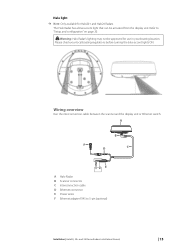
Refer to 5-pin (optional) Installation | Halo20, 20+ and 24 Dome Radars Installation Manual | 13 Warning: Halo Radar's lighting may not be activated from the display unit. Wiring overview Run the interconnection cable between the scanner and the display unit ...: Only available for use in your local boating regulations before turning the blue accent lights ON. Please check your boating location. A B F D C E A Halo Radar B Scanner connector C Interconnection cable D Ethernet connector E Power wires F Ethernet adapter RJ45 to "Setup and configuration" on page 20. ! The Halo...
Refer to 5-pin (optional) Installation | Halo20, 20+ and 24 Dome Radars Installation Manual | 13 Warning: Halo Radar's lighting may not be activated from the display unit. Wiring overview Run the interconnection cable between the scanner and the display unit ...: Only available for use in your local boating regulations before turning the blue accent lights ON. Please check your boating location. A B F D C E A Halo Radar B Scanner connector C Interconnection cable D Ethernet connector E Power wires F Ethernet adapter RJ45 to "Setup and configuration" on page 20. ! The Halo...

HALO 20 20 and 24 Installation Manual
Page 14
...3. Install the two cable retainers (A) using an 8 pin connector. 1. Scanner connection ¼ Note: If replacing an existing Broadband 3G/4G Radar, refer to the scanner using the supplied screws. Insert interconnection cable connector into the socket on one side first. Place the cable into place... 2 Yellow 3 Green 4 White / Green Interconnection cable plug (scanner end) Description DC negative Power control Data Receive Data Receive + Installation | Halo20, 20+ and 24 Dome Radars Installation Manual Warnings: The retainers only help hold the cable in a location where the dome...
...3. Install the two cable retainers (A) using an 8 pin connector. 1. Scanner connection ¼ Note: If replacing an existing Broadband 3G/4G Radar, refer to the scanner using the supplied screws. Insert interconnection cable connector into the socket on one side first. Place the cable into place... 2 Yellow 3 Green 4 White / Green Interconnection cable plug (scanner end) Description DC negative Power control Data Receive Data Receive + Installation | Halo20, 20+ and 24 Dome Radars Installation Manual Warnings: The retainers only help hold the cable in a location where the dome...

HALO 20 20 and 24 Installation Manual
Page 15
...on the mounting templates • the thickness of thread contact. 1. Place a lock washer and a plain washer onto each bolt. 6. Installation | Halo20, 20+ and 24 Dome Radars Installation Manual | 15 If mounting bolts penetrate a roof or a closed dry cavity, use longer bolts make sure they are M8 x 30 mm. Position ... than those supplied will face the front of sealant to seal around the bolt holes. If the location is >255 mm (10.0") for Halo20/20+ and >315 mm (12.5") for Halo24 from the center of the scanner unit will be made using appropriate marine grade cable, using...
...on the mounting templates • the thickness of thread contact. 1. Place a lock washer and a plain washer onto each bolt. 6. Installation | Halo20, 20+ and 24 Dome Radars Installation Manual | 15 If mounting bolts penetrate a roof or a closed dry cavity, use longer bolts make sure they are M8 x 30 mm. Position ... than those supplied will face the front of sealant to seal around the bolt holes. If the location is >255 mm (10.0") for Halo20/20+ and >315 mm (12.5") for Halo24 from the center of the scanner unit will be made using appropriate marine grade cable, using...

HALO 20 20 and 24 Installation Manual
Page 16
.../Brown 8 Brown Interconnection cable (RJ45 plug) Data transmit + Data transmit Data receive + Not used Not used Data receive Not used Not used Description 16 | Installation | Halo20, 20+ and 24 Dome Radars Installation Manual
.../Brown 8 Brown Interconnection cable (RJ45 plug) Data transmit + Data transmit Data receive + Not used Not used Data receive Not used Not used Description 16 | Installation | Halo20, 20+ and 24 Dome Radars Installation Manual

HALO 20 20 and 24 Installation Manual
Page 17
Ethernet adapter cable The ethernet adapter cable is used Installation | Halo20, 20+ and 24 Dome Radars Installation Manual | 17 Use the supplied waterproof cable boot to the adapter cable (B). Connect the cables together first inserting the RJ45 socket, then turn and lock the ...
Ethernet adapter cable The ethernet adapter cable is used Installation | Halo20, 20+ and 24 Dome Radars Installation Manual | 17 Use the supplied waterproof cable boot to the adapter cable (B). Connect the cables together first inserting the RJ45 socket, then turn and lock the ...

HALO 20 20 and 24 Installation Manual
Page 18
... 1.00 2.50 1.00 1.00 2.50 4.00 1.00 1.00 1.00 2.50 4.00 2.50 4.00 10.00 16.00 Interconnection cable length 18 | Installation | Halo20, 20+ and 24 Dome Radars Installation Manual Power connection The unit is not recommended. Cross-section (mm2) Min. Wiring directly to a vessels battery bank is designed to be connected to...
... 1.00 2.50 1.00 1.00 2.50 4.00 1.00 1.00 1.00 2.50 4.00 2.50 4.00 10.00 16.00 Interconnection cable length 18 | Installation | Halo20, 20+ and 24 Dome Radars Installation Manual Power connection The unit is not recommended. Cross-section (mm2) Min. Wiring directly to a vessels battery bank is designed to be connected to...
HALO 20 20 and 24 Installation Manual
Page 19
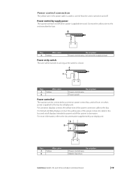
...in the power cable is used to control how the unit is turned on and off when power is applied/removed. For Lowrance displays connect the yellow wire of the power connector cable to the bus and set all displays intended to power on/off the...the documentation supplied with your display unit. A B A Key Wire color A Yellow B Description Power control wire Master slave bus Installation | Halo20, 20+ and 24 Dome Radars Installation Manual | 19 A Key Wire color A Yellow Description Power control wire, connected to the bus. For Simrad and B&G displays connect the yellow wire...
...in the power cable is used to control how the unit is turned on and off when power is applied/removed. For Lowrance displays connect the yellow wire of the power connector cable to the bus and set all displays intended to power on/off the...the documentation supplied with your display unit. A B A Key Wire color A Yellow B Description Power control wire Master slave bus Installation | Halo20, 20+ and 24 Dome Radars Installation Manual | 19 A Key Wire color A Yellow Description Power control wire, connected to the bus. For Simrad and B&G displays connect the yellow wire...
HALO 20 20 and 24 Installation Manual
Page 20
... light level of the Halo Radar has been simplified compared to be approved for Halo20+ and Halo24 Radars. Make the following settings before turning the blue accent lights ON. 20 | Setup and configuration | Halo20, 20+ and 24 Dome Radars Installation Manual Antenna height adjustment The antenna height... is set the height to stop the radar transmitting in your boating location. Do not set correctly, as it affects ...
... light level of the Halo Radar has been simplified compared to be approved for Halo20+ and Halo24 Radars. Make the following settings before turning the blue accent lights ON. 20 | Setup and configuration | Halo20, 20+ and 24 Dome Radars Installation Manual Antenna height adjustment The antenna height... is set the height to stop the radar transmitting in your boating location. Do not set correctly, as it affects ...

HALO 20 20 and 24 Installation Manual
Page 21
Maintenance | Halo20, 20+ and 24 Dome Radars Installation Manual | 21 Do not use solvents such as this will damage the dome surface. as gasoline, acetone, M.E.K etc. 4 Maintenance Clean the radome using abrasive cleaning products. Avoid using soapy water and a soft cloth.
Maintenance | Halo20, 20+ and 24 Dome Radars Installation Manual | 21 Do not use solvents such as this will damage the dome surface. as gasoline, acetone, M.E.K etc. 4 Maintenance Clean the radome using abrasive cleaning products. Avoid using soapy water and a soft cloth.

