
HALO 20 20 and 24 Installation Manual
Page 5
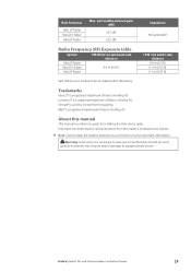
...Lowrance® is a registered trademark of Navico Holding AS. Warning: Used when it is a registered trademark of injury and/or damage to a comment or some important information. ! Preface | Halo20, 20+ and 24 Dome Radars Installation Manual | 5 Halo Antennas Halo 20 Radar Halo20+ Radar Halo24 Radar... to equipment/personnel. permissible antenna gain (dBi) 22.5 dBi 23.5 dBi Impedance Not applicable Radio Frequency (RF) Exposure table System Halo20 Radar Halo20+ Radar Halo24 Radar 100 W/m2 occupational safe distance 0.0 m (0.0 ft) 10 W /m2 public safe distance 0.0 m (0.0 ft) 0.1 m ...
...Lowrance® is a registered trademark of Navico Holding AS. Warning: Used when it is a registered trademark of injury and/or damage to a comment or some important information. ! Preface | Halo20, 20+ and 24 Dome Radars Installation Manual | 5 Halo Antennas Halo 20 Radar Halo20+ Radar Halo24 Radar... to equipment/personnel. permissible antenna gain (dBi) 22.5 dBi 23.5 dBi Impedance Not applicable Radio Frequency (RF) Exposure table System Halo20 Radar Halo20+ Radar Halo24 Radar 100 W/m2 occupational safe distance 0.0 m (0.0 ft) 10 W /m2 public safe distance 0.0 m (0.0 ft) 0.1 m ...
HALO 20 20 and 24 Installation Manual
Page 6
... control connection 20 Setup and configuration 21 Maintenance 22 Replacing a Broadband 3G/4G Radar 22 RI-10 Radar interface box and wiring 23 Troubleshooting 23 Status LED 23 Error messages 24 Error codes 25 Dimensional drawings 25 Halo dome radar dimensions 27 Technical specifications 27 Halo20/20+ Radar 28 Halo24 Radar 29 Accessories 6 | Contents | Halo20, 20+ and 24 Dome Radars Installation Manual
... control connection 20 Setup and configuration 21 Maintenance 22 Replacing a Broadband 3G/4G Radar 22 RI-10 Radar interface box and wiring 23 Troubleshooting 23 Status LED 23 Error messages 24 Error codes 25 Dimensional drawings 25 Halo dome radar dimensions 27 Technical specifications 27 Halo20/20+ Radar 28 Halo24 Radar 29 Accessories 6 | Contents | Halo20, 20+ and 24 Dome Radars Installation Manual
HALO 20 20 and 24 Installation Manual
Page 7
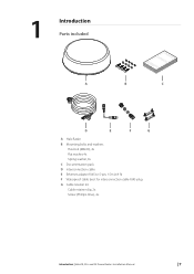
1 Introduction Parts included A B bbbbaaaannnnddddgggg....ccccoooommmm EEEENNNNGGGGLLLLIIIISSSSHHHHIIIInnnnssssttttaaaallllllllaaaattttiiiioooonnnn MMMMaaaannnnuuuuaaaallll C D E F G A Halo Radar B Mounting bolts and washers Hex bolt (M8x30), 4x Flat washer, 4x Spring washer, 4x C Documentation pack D Interconnection cable E Ethernet adapter RJ45 to 5-pin, 1.5m (4.9 ft) F Waterproof cable boot for interconnection cable RJ45 plug G Cable retainer kit Cable retainer clip, 2x Screw (Phillips drive), 4x Introduction | Halo20, 20+ and 24 Dome Radars Installation Manual | 7
1 Introduction Parts included A B bbbbaaaannnnddddgggg....ccccoooommmm EEEENNNNGGGGLLLLIIIISSSSHHHHIIIInnnnssssttttaaaallllllllaaaattttiiiioooonnnn MMMMaaaannnnuuuuaaaallll C D E F G A Halo Radar B Mounting bolts and washers Hex bolt (M8x30), 4x Flat washer, 4x Spring washer, 4x C Documentation pack D Interconnection cable E Ethernet adapter RJ45 to 5-pin, 1.5m (4.9 ft) F Waterproof cable boot for interconnection cable RJ45 plug G Cable retainer kit Cable retainer clip, 2x Screw (Phillips drive), 4x Introduction | Halo20, 20+ and 24 Dome Radars Installation Manual | 7
HALO 20 20 and 24 Installation Manual
Page 8
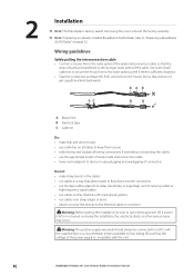
... clearance. • Tape the conductors and tape the RJ45 connector to turn electrical power off. 2 Installation ¼ Note: The Halo Radar is transferred to fuse rating). Use some small cable ties to secure the mouse line to the outer jacket as well if there is...leave room adjacent to device to ease plugging and unplugging of the power supply is compatible with the unit. 8 | Installation | Halo20, 20+ and 24 Dome Radars Installation Manual Warning: Before starting the installation, be connected to (+) DC with mechanical systems • run cables so they interfere ...
... clearance. • Tape the conductors and tape the RJ45 connector to turn electrical power off. 2 Installation ¼ Note: The Halo Radar is transferred to fuse rating). Use some small cable ties to secure the mouse line to the outer jacket as well if there is...leave room adjacent to device to ease plugging and unplugging of the power supply is compatible with the unit. 8 | Installation | Halo20, 20+ and 24 Dome Radars Installation Manual Warning: Before starting the installation, be connected to (+) DC with mechanical systems • run cables so they interfere ...
HALO 20 20 and 24 Installation Manual
Page 9
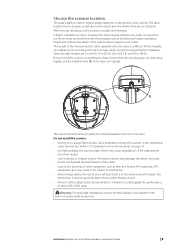
... deciding on to a large flat roof area. Warning: For dual radar installations, ensure the Halo Radar is likely to generate false echoes and/or shadow zones • where it will degrade the performance of the radar • close to lamps or exhaust outlets. A The scanner should...are 5 m (16 ft) 10 m (33 ft), 20 m (65.5 ft) and 30 m (98 ft). Installation | Halo20, 20+ and 24 Dome Radars Installation Manual | 9 Higher installation height also reduces the ability of installations. Choose the scanner location The radar's ability to detect targets greatly depends on a pedestal or ...
... deciding on to a large flat roof area. Warning: For dual radar installations, ensure the Halo Radar is likely to generate false echoes and/or shadow zones • where it will degrade the performance of the radar • close to lamps or exhaust outlets. A The scanner should...are 5 m (16 ft) 10 m (33 ft), 20 m (65.5 ft) and 30 m (98 ft). Installation | Halo20, 20+ and 24 Dome Radars Installation Manual | 9 Higher installation height also reduces the ability of installations. Choose the scanner location The radar's ability to detect targets greatly depends on a pedestal or ...
HALO 20 20 and 24 Installation Manual
Page 10
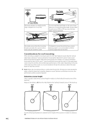
... Minimum distance to the furthest forward corner of any time the Halo Radar is a guide to determine scanner height in relation to tilt the scanner angle down at the front. Installation | Halo20, 20+ and 24 Dome Radars Installation Manual If installed on the same beam plane as per ... performance section, else performance will decrease performance of the hard top. Pulse Radar STBY Do not install the Halo Radar on power boats that the vertical radar beam extends 25° above and below horizontal for Halo20/20+ and 22° above and below horizontal for Halo24. 50% of...
... Minimum distance to the furthest forward corner of any time the Halo Radar is a guide to determine scanner height in relation to tilt the scanner angle down at the front. Installation | Halo20, 20+ and 24 Dome Radars Installation Manual If installed on the same beam plane as per ... performance section, else performance will decrease performance of the hard top. Pulse Radar STBY Do not install the Halo Radar on power boats that the vertical radar beam extends 25° above and below horizontal for Halo20/20+ and 22° above and below horizontal for Halo24. 50% of...
HALO 20 20 and 24 Installation Manual
Page 11
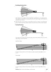
... loss 50% of beam power 50% of dimension (A), increase the height (B) by 45 mm (1.77"). Halo20/20+ Radar 3.0 m2.80 m2.60 m2.40 m2.20 m2.00 m1.80 m1.60 m1.40 m1.20 m1.00 m0.80 m 0.55 m A 0 mm 60 mm 100 mm 190 m1243m55 mm mm 280...beam power Above illustrates an installation with the Halo Radar mounted directly on to clear the hard top. This installation could suffer decreased performance as the radar energy is constructed of any form of the radar energy to a large hard top. Installation | Halo20, 20+ and 24 Dome Radars Installation Manual | 11 Good performance 12.5&#...
... loss 50% of beam power 50% of dimension (A), increase the height (B) by 45 mm (1.77"). Halo20/20+ Radar 3.0 m2.80 m2.60 m2.40 m2.20 m2.00 m1.80 m1.60 m1.40 m1.20 m1.00 m0.80 m 0.55 m A 0 mm 60 mm 100 mm 190 m1243m55 mm mm 280...beam power Above illustrates an installation with the Halo Radar mounted directly on to clear the hard top. This installation could suffer decreased performance as the radar energy is constructed of any form of the radar energy to a large hard top. Installation | Halo20, 20+ and 24 Dome Radars Installation Manual | 11 Good performance 12.5&#...
HALO 20 20 and 24 Installation Manual
Page 13
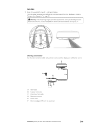
... Run the interconnection cable between the scanner and the display unit or Ethernet switch. Warning: Halo Radar's lighting may not be activated from the display unit. Refer to 5-pin (optional) Installation | Halo20, 20+ and 24 Dome Radars Installation Manual | 13 A B F D C E A Halo Radar B Scanner connector C Interconnection cable D Ethernet connector E Power wires F Ethernet adapter RJ45 to "Setup and configuration...
... Run the interconnection cable between the scanner and the display unit or Ethernet switch. Warning: Halo Radar's lighting may not be activated from the display unit. Refer to 5-pin (optional) Installation | Halo20, 20+ and 24 Dome Radars Installation Manual | 13 A B F D C E A Halo Radar B Scanner connector C Interconnection cable D Ethernet connector E Power wires F Ethernet adapter RJ45 to "Setup and configuration...
HALO 20 20 and 24 Installation Manual
Page 20
... control is the height of which is set to stop the radar transmitting in your boating location. Halo light ¼ Note: Only available for use . Make the following settings before turning the blue accent lights ON. 20 | Setup and configuration | Halo20, 20+ and 24 Dome Radars Installation Manual Antenna height adjustment The antenna height is not...
... control is the height of which is set to stop the radar transmitting in your boating location. Halo light ¼ Note: Only available for use . Make the following settings before turning the blue accent lights ON. 20 | Setup and configuration | Halo20, 20+ and 24 Dome Radars Installation Manual Antenna height adjustment The antenna height is not...
HALO 20 20 and 24 Installation Manual
Page 22
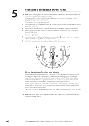
... on page 19. Check the Fuse/circuit breaker rating is recommended to operate. 22 | Replacing a Broadband 3G/4G Radar | Halo20, 20+ and 24 Dome Radars Installation Manual Install the first retainer across the adapter cable using the supplied screws. Use the appropriate tools to strip the...on page 27. ¼ Note: Halo dome radars do not require navigation data via the scanner adaptor cable, with Halo 20, 20+ and 24 dome radars. At mounting location: 4. A B RI-10 Radar interface box and wiring It is as described in place when a Halo 20/20+ or Halo24 is connected via Simnet or...
... on page 19. Check the Fuse/circuit breaker rating is recommended to operate. 22 | Replacing a Broadband 3G/4G Radar | Halo20, 20+ and 24 Dome Radars Installation Manual Install the first retainer across the adapter cable using the supplied screws. Use the appropriate tools to strip the...on page 27. ¼ Note: Halo dome radars do not require navigation data via the scanner adaptor cable, with Halo 20, 20+ and 24 dome radars. At mounting location: 4. A B RI-10 Radar interface box and wiring It is as described in place when a Halo 20/20+ or Halo24 is connected via Simnet or...

HALO 20 20 and 24 Installation Manual
Page 25
Dimensional drawings | Halo20, 20+ and 24 Dome Radars Installation Manual | 25 A 7 Dimensional drawings Halo dome radar dimensions B C D Key Halo20/20+ Radar A 223.0 mm (8.78") B 510.0 mm (20.08") C 233.0 mm (9.17") D 141.5 mm (5.57") Dimensions Halo24 Radar 225 mm (8.9") 610 mm (24") 233.0 mm (9.17") 141.5 mm (5.57") Broadband 3G/4G Radar 280 mm (11.02") 488.6 mm (19.24") 233.0 mm (9.17") 141.5 mm (5.57") ¼ Note: The bolt holes are located in the same position for each radar.
Dimensional drawings | Halo20, 20+ and 24 Dome Radars Installation Manual | 25 A 7 Dimensional drawings Halo dome radar dimensions B C D Key Halo20/20+ Radar A 223.0 mm (8.78") B 510.0 mm (20.08") C 233.0 mm (9.17") D 141.5 mm (5.57") Dimensions Halo24 Radar 225 mm (8.9") 610 mm (24") 233.0 mm (9.17") 141.5 mm (5.57") Broadband 3G/4G Radar 280 mm (11.02") 488.6 mm (19.24") 233.0 mm (9.17") 141.5 mm (5.57") ¼ Note: The bolt holes are located in the same position for each radar.

HALO 20 20 and 24 Installation Manual
Page 26
Halo dome radar bottom view C C D D B C C A Key Description A Cable entry area B Cable retention channel C Bolt hole M8 x 30 mm D LED accent light* * Only available for Halo20+ and Halo24 Radars. 26 | Dimensional drawings | Halo20, 20+ and 24 Dome Radars Installation Manual
Halo dome radar bottom view C C D D B C C A Key Description A Cable entry area B Cable retention channel C Bolt hole M8 x 30 mm D LED accent light* * Only available for Halo20+ and Halo24 Radars. 26 | Dimensional drawings | Halo20, 20+ and 24 Dome Radars Installation Manual