
SW420 GL BOARD Manual
Page 1
GLCONTROLLER BOARD MODEL SW420 LIGHT DUTY SWING GATE OPERATOR 2 YEAR WARRANTY Serial located on electrical box cover) Installation Date INTENDED FOR PROFESSIONAL INSTALLATION ONLY. THIS MANUAL IS TO BE LEFT WITH THE PROPERTY OWNER. VISIT WWW.LIFTMASTER.COM TO LOCATE A PROFESSIONAL INSTALLING DEALER IN YOUR AREA. MODEL SW420 IS FOR VEHICULAR PASSAGE GATES ONLY AND IS NOT INTENDED FOR PEDESTRIAN PASSAGE GATE USE.
GLCONTROLLER BOARD MODEL SW420 LIGHT DUTY SWING GATE OPERATOR 2 YEAR WARRANTY Serial located on electrical box cover) Installation Date INTENDED FOR PROFESSIONAL INSTALLATION ONLY. THIS MANUAL IS TO BE LEFT WITH THE PROPERTY OWNER. VISIT WWW.LIFTMASTER.COM TO LOCATE A PROFESSIONAL INSTALLING DEALER IN YOUR AREA. MODEL SW420 IS FOR VEHICULAR PASSAGE GATES ONLY AND IS NOT INTENDED FOR PEDESTRIAN PASSAGE GATE USE.
SW420 GL BOARD Manual
Page 2
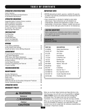
... instructions. • These instructions are not intended to be comprehensive. Because each application is unique, it . HARDWARE KIT SW420 (K77-SW420) PART NO. 01-G0582 02-401-SP 07-2705 10-2111 11-2754 12-2727 40-3505 80-10026 80-206... 3/8-16 Socket Head Bolt 3/8-24 Flat Washer 3/8" QTY. 1 1 1 1 1 3 2 2 4 2 1 2 1 1 WARNING Mechanical CWAUATRIONINNG Electrical CAWUATRIONNING WARNING When you see this manual and follow all components were supplied and received undamaged. Read them . The hazard may come from something WWAARRNNININGG mechanical or from electric shock. TABLE OF...
... instructions. • These instructions are not intended to be comprehensive. Because each application is unique, it . HARDWARE KIT SW420 (K77-SW420) PART NO. 01-G0582 02-401-SP 07-2705 10-2111 11-2754 12-2727 40-3505 80-10026 80-206... 3/8-16 Socket Head Bolt 3/8-24 Flat Washer 3/8" QTY. 1 1 1 1 1 3 2 2 4 2 1 2 1 1 WARNING Mechanical CWAUATRIONINNG Electrical CAWUATRIONNING WARNING When you see this manual and follow all components were supplied and received undamaged. Read them . The hazard may come from something WWAARRNNININGG mechanical or from electric shock. TABLE OF...

SW420 GL BOARD Manual
Page 6
... gate to promote pedestrian usage. A minimum of two (2) WARNING SIGNS shall be located where the transmission of the gate where easily visible. 11. Reference owner's manual regarding placement of a gate system. b. For a gate operator utilizing a contact sensor such as a component part of non-contact sensor for entrapment protection functions shall be...
... gate to promote pedestrian usage. A minimum of two (2) WARNING SIGNS shall be located where the transmission of the gate where easily visible. 11. Reference owner's manual regarding placement of a gate system. b. For a gate operator utilizing a contact sensor such as a component part of non-contact sensor for entrapment protection functions shall be...
SW420 GL BOARD Manual
Page 7
... Class IV vehicular horizontal slide gates: 3.2.1 All weight bearing exposed rollers 8 feet (2.44 m), or less, above grade. 1.5 An existing gate latch shall be disabled when a manually operated gate is required to perform their intended function. 3.1.5 All gates shall be designed with security related parameters specific to the designed fully open and...
... Class IV vehicular horizontal slide gates: 3.2.1 All weight bearing exposed rollers 8 feet (2.44 m), or less, above grade. 1.5 An existing gate latch shall be disabled when a manually operated gate is required to perform their intended function. 3.1.5 All gates shall be designed with security related parameters specific to the designed fully open and...
SW420 GL BOARD Manual
Page 12
... pin from opening and damage to the gate. 8. When the manual release pin is installed incorrectly, the gate will mount to the operator may result! 6. Secure the extension arm to drop down, the control arm should ...
... pin from opening and damage to the gate. 8. When the manual release pin is installed incorrectly, the gate will mount to the operator may result! 6. Secure the extension arm to drop down, the control arm should ...
SW420 GL BOARD Manual
Page 13
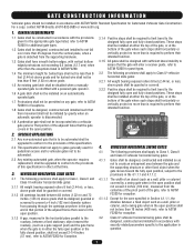
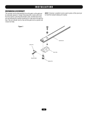
Disconnect the control arm from the gate, so the gate can be opened or closed normally. NOTE: If desired, a padlock can be used in place. The arm should now be free and the gate can be manually opened and closed . Figure 1 Clevis Pin Hairpin Cotter Control Arm Drive Hub Release Pin 13 INSTALLATION MECHANICAL DISCONNECT The operator can be disconnected from the drive hub by removing the hairpin cotter and then the clevis pin and allowing the manual release pin to hold the manual release pin in place of the clevis pin to drop down through the hub.
Disconnect the control arm from the gate, so the gate can be opened or closed normally. NOTE: If desired, a padlock can be used in place. The arm should now be free and the gate can be manually opened and closed . Figure 1 Clevis Pin Hairpin Cotter Control Arm Drive Hub Release Pin 13 INSTALLATION MECHANICAL DISCONNECT The operator can be disconnected from the drive hub by removing the hairpin cotter and then the clevis pin and allowing the manual release pin to hold the manual release pin in place of the clevis pin to drop down through the hub.
SW420 GL BOARD Manual
Page 17
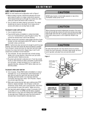
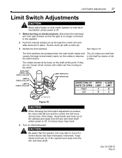
... on J1 terminal strip to cause the gate to point in desired position. Rotate cam away from gate bracket so gate is off power. Push manual release pin up through the control arm, slide clevis pin in close direction. 5. TO ADJUST CLOSE LIMIT SWITCH 3. Repeat steps 3 and 4 until collars are held...
... on J1 terminal strip to cause the gate to point in desired position. Rotate cam away from gate bracket so gate is off power. Push manual release pin up through the control arm, slide clevis pin in close direction. 5. TO ADJUST CLOSE LIMIT SWITCH 3. Repeat steps 3 and 4 until collars are held...
SW420 GL BOARD Manual
Page 18
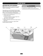
To do so please perform the following steps: 1. Loosen the two screws holding the hall bracket to ensure that the sensor is: a. Manually rotate pulley to the frame. 2. AVERT AVERT ATTEN Cable Operator Chassis Mounting Screws (2) Bracket Pulley Magnet AVER Pulley ADVERTENCIA PRECAUCIÓN 18 ADJUSTMENT RPM SENSOR (...
To do so please perform the following steps: 1. Loosen the two screws holding the hall bracket to ensure that the sensor is: a. Manually rotate pulley to the frame. 2. AVERT AVERT ATTEN Cable Operator Chassis Mounting Screws (2) Bracket Pulley Magnet AVER Pulley ADVERTENCIA PRECAUCIÓN 18 ADJUSTMENT RPM SENSOR (...

SW420 GL BOARD Manual
Page 20
... 8 & 5 - Residential Radio (single button) Input These terminals are intended for mounting, wiring, programming and adjustment. Accessories that you follow the UL guidelines presented throughout the manual. NOTE: Will not override a double entrapment (signalled by activating the remote control when the gate is closed or between limits. Interrupt (Safety) Loop Input These...
... 8 & 5 - Residential Radio (single button) Input These terminals are intended for mounting, wiring, programming and adjustment. Accessories that you follow the UL guidelines presented throughout the manual. NOTE: Will not override a double entrapment (signalled by activating the remote control when the gate is closed or between limits. Interrupt (Safety) Loop Input These...

SW420 GL BOARD Manual
Page 27
...learn the motor. If both primary and secondary power is making excessive noise. Low primary (high voltage) power. Perform a visual inspection of this manual. NOTE: Repeated motor problems indicate poor primary power. An accessory is solid the board needs to move . Improper J4 Connector Wiring (Master/Second... unit's on /off switch. Measure the voltage at the top right of the operator's rating when running . Check the number of this manual. Low secondary (low voltage) power. If the high voltage power is good and the low voltage power is bad, check to run. ...
...learn the motor. If both primary and secondary power is making excessive noise. Low primary (high voltage) power. Perform a visual inspection of this manual. NOTE: Repeated motor problems indicate poor primary power. An accessory is solid the board needs to move . Improper J4 Connector Wiring (Master/Second... unit's on /off switch. Measure the voltage at the top right of the operator's rating when running . Check the number of this manual. Low secondary (low voltage) power. If the high voltage power is good and the low voltage power is bad, check to run. ...
SW420 GL BOARD Manual
Page 29
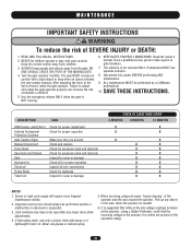
... the force or the limit of SEVERE INJURY or DEATH: 1. The entrance is suggested that the incoming voltage to be performed by a LiftMaster professional. 10. When servicing, please do some "house cleaning" of INJURY or DEATH. 5. It is for wear or damage X ... Check for proper adjustment X X External Entrapment Check for proper operation X X Protection Systems Gate Caution Signs Make sure they are present X X Manual Disconnect Check and operate X X Drive Chain Check for excessive slack and lubricate X X Sprockets and Pulleys Check for excessive slack and lubricate X...
... the force or the limit of SEVERE INJURY or DEATH: 1. The entrance is suggested that the incoming voltage to be performed by a LiftMaster professional. 10. When servicing, please do some "house cleaning" of INJURY or DEATH. 5. It is for wear or damage X ... Check for proper adjustment X X External Entrapment Check for proper operation X X Protection Systems Gate Caution Signs Make sure they are present X X Manual Disconnect Check and operate X X Drive Chain Check for excessive slack and lubricate X X Sprockets and Pulleys Check for excessive slack and lubricate X...
SW420 GL BOARD Manual
Page 34
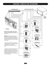
...CLOSE STOP INTERRUPT (SAFETY) LOOP INPUT (N.O.) OBSTRUCTION OPEN EDGE/PHOTO EYE INPUT (N.O.) OBSTRUCTION CLOSE EDGE/PHOTO EYE INPUT (N.O.) RESIDENTIAL RADIO (SINGLE BUTTON) INPUT (N.O.) SW420 Operator 34 CONTROL CONNECTION DIAGRAMS J1 TERMINAL BLOCK 1 2 3 4 5 6 7 8 9 10 11 12 13 14 15 16 Field Wiring Terminal Blocks R1... increase in safety. * We strongly recommend that are normally open and momentary, except the stop (N.C.). SEE OWNERS MANUAL FOR WIRING DISTANCES AND WIRE GAUGE INFORMATION. WARNING: All controls that you follow the instructions provided by the manufacturer when...
...CLOSE STOP INTERRUPT (SAFETY) LOOP INPUT (N.O.) OBSTRUCTION OPEN EDGE/PHOTO EYE INPUT (N.O.) OBSTRUCTION CLOSE EDGE/PHOTO EYE INPUT (N.O.) RESIDENTIAL RADIO (SINGLE BUTTON) INPUT (N.O.) SW420 Operator 34 CONTROL CONNECTION DIAGRAMS J1 TERMINAL BLOCK 1 2 3 4 5 6 7 8 9 10 11 12 13 14 15 16 Field Wiring Terminal Blocks R1... increase in safety. * We strongly recommend that are normally open and momentary, except the stop (N.C.). SEE OWNERS MANUAL FOR WIRING DISTANCES AND WIRE GAUGE INFORMATION. WARNING: All controls that you follow the instructions provided by the manufacturer when...
SW420 S3 BOARD Manual
Page 2
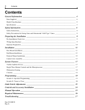
... Obstruction Sensing 18 Circuitry 18 Programming 19 Switch #1: Operator Programming 19 Switch #2: Timer to Close 20 Limit Switch Adjustments 21 Controls and Accessory Installation 24 Manual Operation 25 Required Maintenance 26 Troubleshooting 27 Doc 01-G0610 Rev A
... Obstruction Sensing 18 Circuitry 18 Programming 19 Switch #1: Operator Programming 19 Switch #2: Timer to Close 20 Limit Switch Adjustments 21 Controls and Accessory Installation 24 Manual Operation 25 Required Maintenance 26 Troubleshooting 27 Doc 01-G0610 Rev A

SW420 S3 BOARD Manual
Page 3
Power 27 2. Gear Reducer 30 General Reference Information 30 Features and Program Troubleshooting review 30 Parts List - Please leave this manual at the job site, preferably with the end user or facility manager. Primary Voltage Circuit 28 4. SW420 31 Warranty Policy 33 IMPORTANT! Read and follow all instructions. Low Voltage Circuit 29 5. Doc 01-G0610 Rev A Accessories 28 3. This gate operator is intended for use on a gate that swings in an arc in a horizontal plane. Contents 3 1.
Power 27 2. Gear Reducer 30 General Reference Information 30 Features and Program Troubleshooting review 30 Parts List - Please leave this manual at the job site, preferably with the end user or facility manager. Primary Voltage Circuit 28 4. SW420 31 Warranty Policy 33 IMPORTANT! Read and follow all instructions. Low Voltage Circuit 29 5. Doc 01-G0610 Rev A Accessories 28 3. This gate operator is intended for use on a gate that swings in an arc in a horizontal plane. Contents 3 1.
SW420 S3 BOARD Manual
Page 6
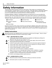
... access separate from vehicular entrance. 5 Confirm gate system design reduces traffic backup. 6 Confirm warning signage is specified by Installation and Maintenance Manual for application type, gate size and frequency of use. 2 Confirm ALL appropriate safety features, such as gate edges, photo-electric sensors,... Instructions are comprised of all moving parts. Doc 01-G0610 Rev A Each gate system is safe for the user as well as manual disconnect mechanism procedure. 10 Confirm control design prohibits unauthorized use . A gate operator can result in its intended use . The gate ...
... access separate from vehicular entrance. 5 Confirm gate system design reduces traffic backup. 6 Confirm warning signage is specified by Installation and Maintenance Manual for application type, gate size and frequency of use. 2 Confirm ALL appropriate safety features, such as gate edges, photo-electric sensors,... Instructions are comprised of all moving parts. Doc 01-G0610 Rev A Each gate system is safe for the user as well as manual disconnect mechanism procedure. 10 Confirm control design prohibits unauthorized use . A gate operator can result in its intended use . The gate ...
SW420 S3 BOARD Manual
Page 7
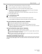
... while operating controls. 6 Install two or more warning signs on the gate to alert persons in the area of gate system. 3 Leave Installation and Maintenance Manual and Safety Information with end user. SECONDARY ENTRAPMENT PROTECTION It is recommended that the RF signal is not interfered with sensor for both . DO NOT...
... while operating controls. 6 Install two or more warning signs on the gate to alert persons in the area of gate system. 3 Leave Installation and Maintenance Manual and Safety Information with end user. SECONDARY ENTRAPMENT PROTECTION It is recommended that the RF signal is not interfered with sensor for both . DO NOT...
SW420 S3 BOARD Manual
Page 15
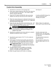
... arm stop on opposite sides of the gate. See Figure 9. 2 Push up any play between the clevis pin and the top of place. 4 When the manual release pin is level and able to the gate. A cotter pin (86-HP-4) keeps the clevis pin (80-2753) from vibrating out of the control... gate at the appropriate height. 10 Attach the gate bracket with the clevis pin (80-2753). 3 Using the 3/8" washers (80-206-65), take up the manual release pin (80-2752) from opening and damage to the extension arm. The gate bracket should swivel freely about the hub. stop .
... arm stop on opposite sides of the gate. See Figure 9. 2 Push up any play between the clevis pin and the top of place. 4 When the manual release pin is level and able to the gate. A cotter pin (86-HP-4) keeps the clevis pin (80-2753) from vibrating out of the control... gate at the appropriate height. 10 Attach the gate bracket with the clevis pin (80-2753). 3 Using the 3/8" washers (80-206-65), take up the manual release pin (80-2752) from opening and damage to the extension arm. The gate bracket should swivel freely about the hub. stop .

SW420 S3 BOARD Manual
Page 18
... an open circuits for line-of-sight devices and out-of-sight devices such as a pushbutton within site of R.P.Ms. will restart the gate. Either a manual device such as open loops or radio controls. Doc 01-G0610 Rev A A renewed wired input will cause the gate to this circuit board. Approximately 1/2 second...
... an open circuits for line-of-sight devices and out-of-sight devices such as a pushbutton within site of R.P.Ms. will restart the gate. Either a manual device such as open loops or radio controls. Doc 01-G0610 Rev A A renewed wired input will cause the gate to this circuit board. Approximately 1/2 second...
SW420 S3 BOARD Manual
Page 21
... if a control device has been improperly connected. CAUTION Be aware that the gate is off , or serious injury may start to the operator. 2 Push the manual release pin up through the control arm and slide clevis pin in place. screws. Keep hands and tools out of set screws until collars are...
... if a control device has been improperly connected. CAUTION Be aware that the gate is off , or serious injury may start to the operator. 2 Push the manual release pin up through the control arm and slide clevis pin in place. screws. Keep hands and tools out of set screws until collars are...
SW420 S3 BOARD Manual
Page 24
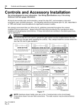
... and Accessory Installation Controls and Accessory Installation See wiring diagram for both the open and close directions. always follow the UL guidelines presented throughout the manual. SECONDARY SAFETY It is for vehicles only and does not provide UL secondary safety for assistance. CLOSE 5 10 SAFETY CLOSE Will reverse (open unless on...
... and Accessory Installation Controls and Accessory Installation See wiring diagram for both the open and close directions. always follow the UL guidelines presented throughout the manual. SECONDARY SAFETY It is for vehicles only and does not provide UL secondary safety for assistance. CLOSE 5 10 SAFETY CLOSE Will reverse (open unless on...


