
SL595 Manual
Page 2
...safety instructions. Model SL595 35 Illustrated Parts - WARNING WIRING Mechanical Power Wiring Installation 8 INSTALWLATAIORN NING Pad Mounting (SL585 only 9 Post Mounting (SL585 & SL595 10 CAUTION Install Gate Bracket and Drive Chain 11 Available Conduit Access for the Electrical Box 12 ... ATTE Operator Maintenance 23 AVERTISSEMENT Solenoid Actuated Brake 24 Friction Clutch 24 HARDWARE KIT SL585/SL595 (K77-34846) Control Board Programming and Features 24-25 AVER Troubleshooting 26-27 Self-Regulating Heater Accessory 28 Single Phase Wiring Diagram 29 Single Phase ...
...safety instructions. Model SL595 35 Illustrated Parts - WARNING WIRING Mechanical Power Wiring Installation 8 INSTALWLATAIORN NING Pad Mounting (SL585 only 9 Post Mounting (SL585 & SL595 10 CAUTION Install Gate Bracket and Drive Chain 11 Available Conduit Access for the Electrical Box 12 ... ATTE Operator Maintenance 23 AVERTISSEMENT Solenoid Actuated Brake 24 Friction Clutch 24 HARDWARE KIT SL585/SL595 (K77-34846) Control Board Programming and Features 24-25 AVER Troubleshooting 26-27 Self-Regulating Heater Accessory 28 Single Phase Wiring Diagram 29 Single Phase ...
SL595 Manual
Page 13
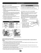
... the limit switch assembly. 2. After adjustment, release plate and ensure it trips the open position (note direction of alignment due to the troubleshooting section. 6. RPM SENSOR (HALL EFFECT) ADJUSTMENT NOTE: Normally the RPM Sensor (Hall Effect) does not need adjustment, but may go .... 3. When power is closing , refer to shipping vibration or rough handling. With the power off, manually move the gate to the troubleshooting section. 5. Disengage the retaining bracket and rotate the close limit nut until it trips the close button and observe the operator's behavior. ...
... the limit switch assembly. 2. After adjustment, release plate and ensure it trips the open position (note direction of alignment due to the troubleshooting section. 6. RPM SENSOR (HALL EFFECT) ADJUSTMENT NOTE: Normally the RPM Sensor (Hall Effect) does not need adjustment, but may go .... 3. When power is closing , refer to shipping vibration or rough handling. With the power off, manually move the gate to the troubleshooting section. 5. Disengage the retaining bracket and rotate the close limit nut until it trips the close button and observe the operator's behavior. ...
SL595 Manual
Page 15
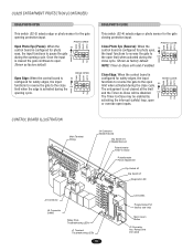
... functions to reverse the gate to -Close Potentiometer Force Adjustment Dip Switch #2 Dip Switch #1 Diagnostic LED J2 Connector J5 Connector SAMS Relay Drive Troubleshooting LEDs J1 Terminal Troubleshooting LEDs 15 Limit LEDs Programming Port (factory use only) Motor Learn Button J3 Connector Aux. ON The entrapment is S2 configured for photo ON...
... functions to reverse the gate to -Close Potentiometer Force Adjustment Dip Switch #2 Dip Switch #1 Diagnostic LED J2 Connector J5 Connector SAMS Relay Drive Troubleshooting LEDs J1 Terminal Troubleshooting LEDs 15 Limit LEDs Programming Port (factory use only) Motor Learn Button J3 Connector Aux. ON The entrapment is S2 configured for photo ON...
SL595 Manual
Page 25
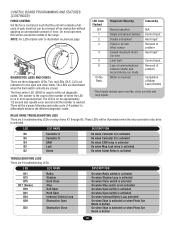
... will be illuminated when the microcontroller relay drive is on for the open override, close limits. DIAGNOSTICS (LEDS AND CODES) There are 5 troubleshooting LEDs on previous page. The number is the count of the number of times the LED is activated. These LEDs will be around the middle... amber LED (DIAG) is on in an 8 second period. The LED is used to illustration on relay drives K1 through K5. RELAY DRIVE TROUBLESHOOTING LEDS There are three diagnostic LEDs. NOTE: For LED location refer to blink out diagnostic codes. Force Control Max. There will be reversed off ...
... will be illuminated when the microcontroller relay drive is on for the open override, close limits. DIAGNOSTICS (LEDS AND CODES) There are 5 troubleshooting LEDs on previous page. The number is the count of the number of times the LED is activated. These LEDs will be around the middle... amber LED (DIAG) is on in an 8 second period. The LED is used to illustration on relay drives K1 through K5. RELAY DRIVE TROUBLESHOOTING LEDS There are three diagnostic LEDs. NOTE: For LED location refer to blink out diagnostic codes. Force Control Max. There will be reversed off ...
SL595 Manual
Page 26
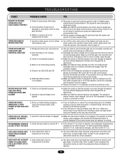
... primary (high voltage) power 2) Problem in the motor 3) Problem in the contactor 4) Problem in voltage. Make sure that the J2 connector is making excessive noise. TROUBLESHOOTING FAULT POSSIBLE CAUSE FIX OPERATOR FAILS TO RUN 1) Improper wired stop control has been installed across terminals TB1-3 and TB1-5 of the terminal strip. ➤...
... primary (high voltage) power 2) Problem in the motor 3) Problem in the contactor 4) Problem in voltage. Make sure that the J2 connector is making excessive noise. TROUBLESHOOTING FAULT POSSIBLE CAUSE FIX OPERATOR FAILS TO RUN 1) Improper wired stop control has been installed across terminals TB1-3 and TB1-5 of the terminal strip. ➤...
SL595 Manual
Page 27
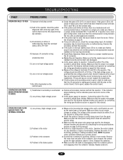
... bind. The operator's manual release, when engaged, will not allow the entrapment sensor to provide feedback to the control board when the operator is moving. TROUBLESHOOTING FAULT POSSIBLE CAUSE FIX MASTER OR SECOND OPERATOR IS NOT FUNCTIONING PROPERLY 1) Failure to cycle power after setup 2) Communication wiring may be wired incorrectly or...
... bind. The operator's manual release, when engaged, will not allow the entrapment sensor to provide feedback to the control board when the operator is moving. TROUBLESHOOTING FAULT POSSIBLE CAUSE FIX MASTER OR SECOND OPERATOR IS NOT FUNCTIONING PROPERLY 1) Failure to cycle power after setup 2) Communication wiring may be wired incorrectly or...

