
SL575 Manual
Page 1
GLCONTROLLER BOARD MODEL SL575 HEAVY DUTY SLIDE GATE OPERATOR 2 YEAR WARRANTY Serial located on electrical box cover) Installation Date MODEL SL575 IS FOR VEHICULAR PASSAGE GATES ONLY AND IS NOT INTENDED FOR PEDESTRIAN PASSAGE GATE USE
GLCONTROLLER BOARD MODEL SL575 HEAVY DUTY SLIDE GATE OPERATOR 2 YEAR WARRANTY Serial located on electrical box cover) Installation Date MODEL SL575 IS FOR VEHICULAR PASSAGE GATES ONLY AND IS NOT INTENDED FOR PEDESTRIAN PASSAGE GATE USE
SL575 Manual
Page 2
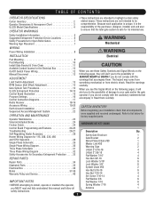
... Programming and Features 24-25 AVER Troubleshooting 26-27 Description Qty. Self-Regulating Heater Accessory 28 Safety Gate Brochure 1 Heater Wiring Diagram for 115, 208, 230, 460 Gate Bracket 2 and 575V Operators 28 Nickel Plated Chain #50 1 Single Phase Schematic 29 Master Link ... and received undamaged. These instructions are intended to list below for its intended use. CARTON INVENTORY Before beginning your gate and/or the gate operator if you do not comply with the warnings that all Antenna 1 safety instructions. 2 Because each application is...
... Programming and Features 24-25 AVER Troubleshooting 26-27 Description Qty. Self-Regulating Heater Accessory 28 Safety Gate Brochure 1 Heater Wiring Diagram for 115, 208, 230, 460 Gate Bracket 2 and 575V Operators 28 Nickel Plated Chain #50 1 Single Phase Schematic 29 Master Link ... and received undamaged. These instructions are intended to list below for its intended use. CARTON INVENTORY Before beginning your gate and/or the gate operator if you do not comply with the warnings that all Antenna 1 safety instructions. 2 Because each application is...
SL575 Manual
Page 3
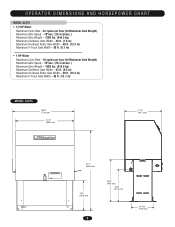
... Maximum Cycle Rate - 18 cycles per hour (At Maximum Gate Weight) Maximum Gate Speed - 10"/sec. (25.4 cm/sec.) Maximum Gate Weight - 1800 lbs. (816.5 kg) Maximum Cantilever Gate Width - 32 ft. (9.8 m) Maximum Overhead Roller Gate Width - 50 ft. (15.2 m) Maximum V-Track Gate Width - 45 ft. (13.7 m) MODEL SL575 28.9" (73.4 cm) 27.5" (69.9 cm) 17.2" (43...
... Maximum Cycle Rate - 18 cycles per hour (At Maximum Gate Weight) Maximum Gate Speed - 10"/sec. (25.4 cm/sec.) Maximum Gate Weight - 1800 lbs. (816.5 kg) Maximum Cantilever Gate Width - 32 ft. (9.8 m) Maximum Overhead Roller Gate Width - 50 ft. (15.2 m) Maximum V-Track Gate Width - 45 ft. (13.7 m) MODEL SL575 28.9" (73.4 cm) 27.5" (69.9 cm) 17.2" (43...
SL575 Manual
Page 4
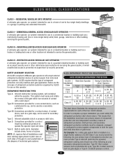
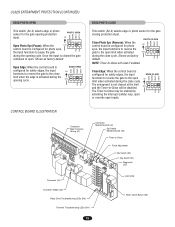
SAFETY ACCESSORY SELECTION All UL325 compliant LiftMaster gate operators will accept external entrapment protection devices to complete a proper installation you must satisfy the entrapment protection chart shown above illustrates the ...of the dangers of entrapment protection correctly matches each of the four UL325 classes. Type D: Connections provided for secondary protection. RESTRICTED ACCESS VEHICULAR GATE OPERATOR A vehicular gate operator (or system) intended for use in which unauthorized access is for use in a guarded industrial location or building such as a multi...
SAFETY ACCESSORY SELECTION All UL325 compliant LiftMaster gate operators will accept external entrapment protection devices to complete a proper installation you must satisfy the entrapment protection chart shown above illustrates the ...of the dangers of entrapment protection correctly matches each of the four UL325 classes. Type D: Connections provided for secondary protection. RESTRICTED ACCESS VEHICULAR GATE OPERATOR A vehicular gate operator (or system) intended for use in which unauthorized access is for use in a guarded industrial location or building such as a multi...
SL575 Manual
Page 5
...and users must be located in a location so that persons will not come in its wiring arranged so the communication between the gate and adjacent structures when opening and closing to prevent a 2-1/4" (6 cm) diameter sphere from reaching over, under the intended end... Rollers • Vertical Posts • Photoelectric Sensors • Instructional and Precautionary Signage 4. The operator is still moving gate or barrier. 12. Swinging gates shall not open position. Activation of a vertical barrier (arm). 5 Reference owner's manual regarding placement of non-contact ...
...and users must be located in a location so that persons will not come in its wiring arranged so the communication between the gate and adjacent structures when opening and closing to prevent a 2-1/4" (6 cm) diameter sphere from reaching over, under the intended end... Rollers • Vertical Posts • Photoelectric Sensors • Instructional and Precautionary Signage 4. The operator is still moving gate or barrier. 12. Swinging gates shall not open position. Activation of a vertical barrier (arm). 5 Reference owner's manual regarding placement of non-contact ...
SL575 Manual
Page 6
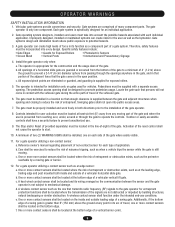
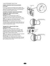
SUGGESTED ENTRAPMENT PROTECTION DEVICE LOCATIONS GATE SYSTEM (MASTER/SECOND SLIDE GATE) Open Edge Gate 2 Open Edge STREET Photo eyes for close cycle Gate 1 Close Edge Photo eyes for open cycle Run twisted wire from loop to operator Interrupt (Safety) Loop 4'T(y1p.2icmal) 4'T(y1p.2icmal) ...LOT Seal loops 1-1/2" (37 mm) Loop wire layer 1/4" (6 mm) or larger depending on loop wire size Photo eyes for open cycle GATE SYSTEM (COMMERCIAL SLIDE GATE) Telephone Entry System Open Edge Close Edge Photo eye for open cycle STREET 8' (2.4Inmt(eS)rarLufoepottyp) Photo eye for close cycle 4' (1.2...
SUGGESTED ENTRAPMENT PROTECTION DEVICE LOCATIONS GATE SYSTEM (MASTER/SECOND SLIDE GATE) Open Edge Gate 2 Open Edge STREET Photo eyes for close cycle Gate 1 Close Edge Photo eyes for open cycle Run twisted wire from loop to operator Interrupt (Safety) Loop 4'T(y1p.2icmal) 4'T(y1p.2icmal) ...LOT Seal loops 1-1/2" (37 mm) Loop wire layer 1/4" (6 mm) or larger depending on loop wire size Photo eyes for open cycle GATE SYSTEM (COMMERCIAL SLIDE GATE) Telephone Entry System Open Edge Close Edge Photo eye for open cycle STREET 8' (2.4Inmt(eS)rarLufoepottyp) Photo eye for close cycle 4' (1.2...
SL575 Manual
Page 7
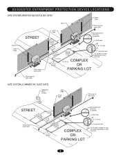
... in a suitable manner using fastening holes. Adjusted or Serviced They cannot retract their hands or feet caught CAUTION between the moving gate grill and the stationary fence post or fence. This entrance is AVERTISSEMENT not a chance of INJURY at any time without prior ... entrance See Safety Brochure Pinch-Point Hazard for Close Direction DO NOT MOUNT ACCESSORIES THAT ARE ACCESSIBLE THROUGH GATE! To prevent entrapment injuries, mount controls Gate Edge for Open Direction Gate Edge for Close Direction ATTENTION at the leading edge, trailing edge and be averted by placing a 4'...
... in a suitable manner using fastening holes. Adjusted or Serviced They cannot retract their hands or feet caught CAUTION between the moving gate grill and the stationary fence post or fence. This entrance is AVERTISSEMENT not a chance of INJURY at any time without prior ... entrance See Safety Brochure Pinch-Point Hazard for Close Direction DO NOT MOUNT ACCESSORIES THAT ARE ACCESSIBLE THROUGH GATE! To prevent entrapment injuries, mount controls Gate Edge for Open Direction Gate Edge for Close Direction ATTENTION at the leading edge, trailing edge and be averted by placing a 4'...
SL575 Manual
Page 8
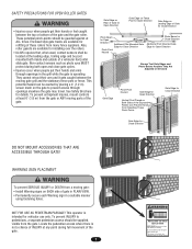
... electrical codes. AVERTISSEMENT • ALL electrical connections MUST be installed on ITS OWN separate circuits. POWER WIARITNGTIENSNTATLLIAOTINON Wiring Specifications (STRANDED COPPER WIRE) AVERTISSEMENT On a Dual Gate System, each unit must be labeled. 8 NOTE: The operator should be properly grounded and connected in accordance with the control station installation. • ALL power...
... electrical codes. AVERTISSEMENT • ALL electrical connections MUST be installed on ITS OWN separate circuits. POWER WIARITNGTIENSNTATLLIAOTINON Wiring Specifications (STRANDED COPPER WIRE) AVERTISSEMENT On a Dual Gate System, each unit must be labeled. 8 NOTE: The operator should be properly grounded and connected in accordance with the control station installation. • ALL power...

SL575 Manual
Page 9
... Concrete Anchor Holes Using Suitable Hardware To Secure Operator To Concrete Anchors Concrete Pad 1/2" Concrete Anchors (4 Required) 9 Drive and Idler Sprocket Toward Gate Side Power and Control Wiring Should Be Run In Separate Conduit 2" to 4" (5.1 to the concrete pad using four 1/2" concrete anchors (not provided... angle can be installed angle in '. Locate electrical conduit, as required, prior to use the same pad mounting hardware, the gate side mounting angle must be unbolted and reversed to 'angle in . Pour concrete pad. 4. INSTALLATION PAD MOUNTING RETRO-FIT INSTALLATION...
... Concrete Anchor Holes Using Suitable Hardware To Secure Operator To Concrete Anchors Concrete Pad 1/2" Concrete Anchors (4 Required) 9 Drive and Idler Sprocket Toward Gate Side Power and Control Wiring Should Be Run In Separate Conduit 2" to 4" (5.1 to the concrete pad using four 1/2" concrete anchors (not provided... angle can be installed angle in '. Locate electrical conduit, as required, prior to use the same pad mounting hardware, the gate side mounting angle must be unbolted and reversed to 'angle in . Pour concrete pad. 4. INSTALLATION PAD MOUNTING RETRO-FIT INSTALLATION...

SL575 Manual
Page 10
...Pipe 14" (35.6 cm) Min Ground Level Depth As Required By Local Codes or Below Frost LIne Figure 3 Drive and Idler Sprocket Toward Gate Side Angle Bracket 3" (7.6 cm) U-bolt (4 required) Power and Control Wiring Should Be Run In Separate Conduit 10 Locate electrical conduit, as ...required, prior to the gate (Figure 2). 2. Posts should be parallel and square to pouring concrete. 3. POST MOUNTING RETRO-FIT INSTALLATION The operators come from the factory configured ...
...Pipe 14" (35.6 cm) Min Ground Level Depth As Required By Local Codes or Below Frost LIne Figure 3 Drive and Idler Sprocket Toward Gate Side Angle Bracket 3" (7.6 cm) U-bolt (4 required) Power and Control Wiring Should Be Run In Separate Conduit 10 Locate electrical conduit, as ...required, prior to the gate (Figure 2). 2. Posts should be parallel and square to pouring concrete. 3. POST MOUNTING RETRO-FIT INSTALLATION The operators come from the factory configured ...
SL575 Manual
Page 11
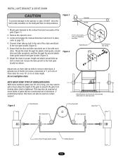
... NOT drive the limit (nuts) actuators on chain take-up bolt to the end of the chain and attach to the rear gate bracket (Figure 2). Gate Bracket AVERTISSEMENT 5. AVERTISSEMENT Adjust nuts on the shaft past their normal positions. Do not overtighten chain. Connect chain take-up bolts to ...the vertical front and rear posts of the gate (Figure 1). 2. This may need to add a brace along the length of the gate to prevent the gate from bowing when chain is to leave a maximum of 1" (2.5 cm) of chain slack for every 10'...
... NOT drive the limit (nuts) actuators on chain take-up bolt to the end of the chain and attach to the rear gate bracket (Figure 2). Gate Bracket AVERTISSEMENT 5. AVERTISSEMENT Adjust nuts on the shaft past their normal positions. Do not overtighten chain. Connect chain take-up bolts to ...the vertical front and rear posts of the gate (Figure 1). 2. This may need to add a brace along the length of the gate to prevent the gate from bowing when chain is to leave a maximum of 1" (2.5 cm) of chain slack for every 10'...
SL575 Manual
Page 12
...connectors. To correct this situation, shut off power at main power source and at the operators electrical disconnect switch. MODEL SL575 DISENGAGEMENT: Pull the disconnect chain and engage it necessary to electrical wiring diagrams on the drive chain before disengaging the system...Green USE1C1O5PPVEROCOLNTDU1CTPORHO.NLY 115V SINGLE PHASE POWER SWITCH ASSEMBLY THREE PHASE All three phase operators will run reversed. If phased incorrectly, the gate operator will have the following: • L1 Black • L2 Black • L3 Black • Ground, Green USE1C1O5PPVEROCOLNTDU1CTPORHO....
...connectors. To correct this situation, shut off power at main power source and at the operators electrical disconnect switch. MODEL SL575 DISENGAGEMENT: Pull the disconnect chain and engage it necessary to electrical wiring diagrams on the drive chain before disengaging the system...Green USE1C1O5PPVEROCOLNTDU1CTPORHO.NLY 115V SINGLE PHASE POWER SWITCH ASSEMBLY THREE PHASE All three phase operators will run reversed. If phased incorrectly, the gate operator will have the following: • L1 Black • L2 Black • L3 Black • Ground, Green USE1C1O5PPVEROCOLNTDU1CTPORHO....
SL575 Manual
Page 13
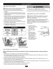
... not need adjustment, but may be adjusted to .010 - .015 of an inch. (The thickness of a business card may go out of gate travel ). 3. The sensor must be centered over the magnet wheel. This system consists of SEVERE INJURY or DEATH: CAUTION • Disconnect power BEFORE...unit's manual disconnect (see page 12), then manually open limit switch. Re-engage the retaining bracket into the electrical box. 4. LIMIT DIRECTION DIRECTION OF GATE TO OPEN RIGHT (Factory Default) LEFT OPEN LIMIT A B CLOSE LIMIT B A Limit Switch Limit Nut A WARNING To reduce the risk of the ...
... not need adjustment, but may be adjusted to .010 - .015 of an inch. (The thickness of a business card may go out of gate travel ). 3. The sensor must be centered over the magnet wheel. This system consists of SEVERE INJURY or DEATH: CAUTION • Disconnect power BEFORE...unit's manual disconnect (see page 12), then manually open limit switch. Re-engage the retaining bracket into the electrical box. 4. LIMIT DIRECTION DIRECTION OF GATE TO OPEN RIGHT (Factory Default) LEFT OPEN LIMIT A B CLOSE LIMIT B A Limit Switch Limit Nut A WARNING To reduce the risk of the ...
SL575 Manual
Page 14
...Opening (Edge/Photo Eye with N.O. This input will have no effect. Activating this input when the gate is closing gate to the open limit. On most operators this input when the gate is opening will stop and alarm. This input will reverse a closing will be reversed off an ...obstruction without applying an unreasonable amount of gate travel but can be disabled until another command is cleared, the gate continues to open limit the Timer-to-Close, if enabled, will have no effect. Photo Eye Input:...
...Opening (Edge/Photo Eye with N.O. This input will have no effect. Activating this input when the gate is closing gate to the open limit. On most operators this input when the gate is opening will stop and alarm. This input will reverse a closing will be reversed off an ...obstruction without applying an unreasonable amount of gate travel but can be disabled until another command is cleared, the gate continues to open limit the Timer-to-Close, if enabled, will have no effect. Photo Eye Input:...
SL575 Manual
Page 15
... the close limit when the edge is configured for safety edges, the input EDGE CLOSE CLED OPED WARN MAG functions to reverse the gate to -Close will reset if enabled. Shown as factory default. Close Photo Eye (Reverse): When the control board is activated during the close cycle. Shown... -Close will be enabled by PH PH activating the interrupt (safety) loop, open or override open . Once the input is configured for the gate closing protection input. ON 1 2 34 The Timer-to open inputs. WARN MAG PHOTO OPEN S2 ON OPED CLED Open Photo Eye (Pause): When the ON...
... the close limit when the edge is configured for safety edges, the input EDGE CLOSE CLED OPED WARN MAG functions to reverse the gate to -Close will reset if enabled. Shown as factory default. Close Photo Eye (Reverse): When the control board is activated during the close cycle. Shown... -Close will be enabled by PH PH activating the interrupt (safety) loop, open or override open . Once the input is configured for the gate closing protection input. ON 1 2 34 The Timer-to open inputs. WARN MAG PHOTO OPEN S2 ON OPED CLED Open Photo Eye (Pause): When the ON...

SL575 Manual
Page 16
... MAG MAGLOCK ENABLED S2 ON ON 1 2 34 OPED CLED PH PH WARNING ENABLE This switch enables the gate "in conjunction with the potentiometer located on the board. When switch is ON, no settings can be a...WARN LT RT LT RT LT RT PH OPED PH OPED SAVE SAVE SAVE Max = 180 sec Min = 0 sec SLIDE GATE S1 ON ON 1 2 34 (Factory Default) RIGHT HAND S1 ON ON 1 2 34 (Factory Default) UNLOCKED S1 ... 2 34 ON 1 2 34 LT SL LT SL (Factory Default) SLIDE/SWING This switch selects slide or swing gate operation, in order to the right. TTC SW RT LEFT HAND S1 ON ON 1 2 34 SAVE LT SL...
... MAG MAGLOCK ENABLED S2 ON ON 1 2 34 OPED CLED PH PH WARNING ENABLE This switch enables the gate "in conjunction with the potentiometer located on the board. When switch is ON, no settings can be a...WARN LT RT LT RT LT RT PH OPED PH OPED SAVE SAVE SAVE Max = 180 sec Min = 0 sec SLIDE GATE S1 ON ON 1 2 34 (Factory Default) RIGHT HAND S1 ON ON 1 2 34 (Factory Default) UNLOCKED S1 ... 2 34 ON 1 2 34 LT SL LT SL (Factory Default) SLIDE/SWING This switch selects slide or swing gate operation, in order to the right. TTC SW RT LEFT HAND S1 ON ON 1 2 34 SAVE LT SL...
SL575 Manual
Page 17
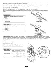
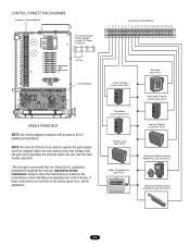
... R4 24 Vac Control Board SINGLE PHASE BOX NOTE: See wiring diagrams shipped with the gate while operating the controls where the user has full view of gate operation. *We strongly recommend that are contrary to operate the gate system, must be installed where the user cannot come into contact with accessory kit...
... R4 24 Vac Control Board SINGLE PHASE BOX NOTE: See wiring diagrams shipped with the gate while operating the controls where the user has full view of gate operation. *We strongly recommend that are contrary to operate the gate system, must be installed where the user cannot come into contact with accessory kit...
SL575 Manual
Page 18
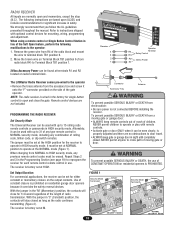
...gate or garage door in HIGH security mode. The jumper must be erased. It must be used with remote controls. ATTENTION When changing from radio block R4) to door travel. Set Output Duration For commercial applications, the receiver can be set at NORMAL position to cross path of children. WARNING The LiftMaster... momentary, except the stop (N.C.). With the jumper in "C" (Constant) position, the contacts will close the gate. We strongly recommend that you follow the UL guidelines presented throughout the manual. PROGRAMMING THE RADIO RECEIVER To prevent...
...gate or garage door in HIGH security mode. The jumper must be erased. It must be used with remote controls. ATTENTION When changing from radio block R4) to door travel. Set Output Duration For commercial applications, the receiver can be set at NORMAL position to cross path of children. WARNING The LiftMaster... momentary, except the stop (N.C.). With the jumper in "C" (Constant) position, the contacts will close the gate. We strongly recommend that you follow the UL guidelines presented throughout the manual. PROGRAMMING THE RADIO RECEIVER To prevent...
SL575 Manual
Page 19
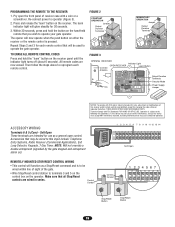
... seconds. 3. Then follow the steps above to this device must accept ANY interference received, including interference that may be used to operate your gate operator. Within 30 seconds, press and hold the "learn " button on the hand-held remote that may cause undesired operation. NOTE: Will... not override a double entrapment (signalled by the gate stopped and entrapment alarm on). 123 56 789 0# 1 2 3 4 5 6 7 8 9 10 11 12 13 14 Soft Open REMOTELY MOUNTED STOP/RESET ...
... seconds. 3. Then follow the steps above to this device must accept ANY interference received, including interference that may be used to operate your gate operator. Within 30 seconds, press and hold the "learn " button on the hand-held remote that may cause undesired operation. NOTE: Will... not override a double entrapment (signalled by the gate stopped and entrapment alarm on). 123 56 789 0# 1 2 3 4 5 6 7 8 9 10 11 12 13 14 Soft Open REMOTELY MOUNTED STOP/RESET ...
SL575 Manual
Page 20
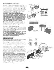
...unit" for every query. If the master gets no communications. The second unit will operate in a master or second mode depending on swing gate operators. NOTE: Do not run Master/Second communication wiring in stand alone mode prior to override a failed accessory such as the power and ...Input 34 56 789 N.O. Terminals 4 & 5 (Com) - Latching this input for use only with the close . NOTE: The control board has built in dual gate configuration accessories may be used as a loop detector or photo-eye. Com 3 4 5 788 Close Override Control Input 1 234 567 12 3 456 N.O. This ...
...unit" for every query. If the master gets no communications. The second unit will operate in a master or second mode depending on swing gate operators. NOTE: Do not run Master/Second communication wiring in stand alone mode prior to override a failed accessory such as the power and ...Input 34 56 789 N.O. Terminals 4 & 5 (Com) - Latching this input for use only with the close . NOTE: The control board has built in dual gate configuration accessories may be used as a loop detector or photo-eye. Com 3 4 5 788 Close Override Control Input 1 234 567 12 3 456 N.O. This ...


