LiftMaster Gate Operator Feature Chart Manual
Page 1
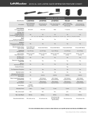
... 325 LISTED GATE OPERATOR FEATURE CHART Model Number Description Battery Backup Powers up when the power's down Security+ 2.0® 3 Channel Receiver Virtually eliminates interference and extends range MyQ® Controls your gate from anywhere with your smartphone P3 Motor® Meets the exact requirements needed to move your gate Monitored Safety Inputs (Color Coded) Exceptional Standby Power Best-in-Class Solar Performance* DC Motor with Soft Start/Stop Diagnostic Code Display2 Digit LED Wireless Dual-Gate Operation...
... 325 LISTED GATE OPERATOR FEATURE CHART Model Number Description Battery Backup Powers up when the power's down Security+ 2.0® 3 Channel Receiver Virtually eliminates interference and extends range MyQ® Controls your gate from anywhere with your smartphone P3 Motor® Meets the exact requirements needed to move your gate Monitored Safety Inputs (Color Coded) Exceptional Standby Power Best-in-Class Solar Performance* DC Motor with Soft Start/Stop Diagnostic Code Display2 Digit LED Wireless Dual-Gate Operation...
LiftMaster Gate Operator Feature Chart Manual
Page 2
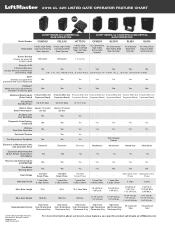
... Gate Operator Battery Backup Powers up when the 146 cycles 208 cycles 112 cycles - - - - Yes Yes - - - - Electronic or Mechanical Limits with Automatic Force Electronic Electronic Electronic Mechanical Mechanical Mechanical Mechanical Expansion Board Included (2) Aux Relays, Quick Close/ Yes Anti-Tailgate Yes Yes Yes Yes Yes Yes Plug-in -class features, see specific product sell sheets at LiftMaster.com Gate Weight 1600 lbs. Diagnostic Code Display2 Digit LED...
... Gate Operator Battery Backup Powers up when the 146 cycles 208 cycles 112 cycles - - - - Yes Yes - - - - Electronic or Mechanical Limits with Automatic Force Electronic Electronic Electronic Mechanical Mechanical Mechanical Mechanical Expansion Board Included (2) Aux Relays, Quick Close/ Yes Anti-Tailgate Yes Yes Yes Yes Yes Yes Plug-in -class features, see specific product sell sheets at LiftMaster.com Gate Weight 1600 lbs. Diagnostic Code Display2 Digit LED...

SL3000101U Installation Manual
Page 1
ELITE SERIES COMMERCIAL HIGH-TRAFFIC AC SLIDE GATE OPERATOR INSTALLATION MANUAL Model SL3000U SL3000101U 1 HP Single Phase SL3000103U 1 HP Three Phase SL3000501U 1/2 HP Single Phase • THIS PRODUCT IS TO BE INSTALLED AND SERVICED BY A TRAINED GATE SYSTEMS TECHNICIAN ONLY. • This model is for use on vehicular passage gates ONLY and not intended for use on pedestrian passage gates. • This model is intended for use in Class I, II, III and...
ELITE SERIES COMMERCIAL HIGH-TRAFFIC AC SLIDE GATE OPERATOR INSTALLATION MANUAL Model SL3000U SL3000101U 1 HP Single Phase SL3000103U 1 HP Three Phase SL3000501U 1/2 HP Single Phase • THIS PRODUCT IS TO BE INSTALLED AND SERVICED BY A TRAINED GATE SYSTEMS TECHNICIAN ONLY. • This model is for use on vehicular passage gates ONLY and not intended for use on pedestrian passage gates. • This model is intended for use in Class I, II, III and...
SL3000101U Installation Manual
Page 2
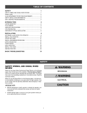
... 2 SAFETY INSTALLATION INFORMATION 3 GATE CONSTRUCTION INFORMATION 4 INTRODUCTION 5 CARTON INVENTORY 5 TOOLS NEEDED 5 OPERATOR SPECIFICATIONS 6 SITE PREPARATION 7 OVERVIEW OF TYPICAL INSTALLATION 8 INSTALLATION 9 DETERMINE LOCATION FOR THE OPERATOR 9 INSTALL THE OPERATOR 10 ATTACH THE CHAIN 11 INSTALL ENTRAPMENT PROTECTION 12 EARTH GROUND ROD 14 POWER WIRING 14 DUAL GATES ONLY 16 INSTALL THE COVER 18 OBSTRUCTION TEST 18 BASIC TROUBLESHOOTING 19 SAFETY SAFETY SYMBOL AND SIGNAL WORD REVIEW When you see this manual and follow all safety instructions...
... 2 SAFETY INSTALLATION INFORMATION 3 GATE CONSTRUCTION INFORMATION 4 INTRODUCTION 5 CARTON INVENTORY 5 TOOLS NEEDED 5 OPERATOR SPECIFICATIONS 6 SITE PREPARATION 7 OVERVIEW OF TYPICAL INSTALLATION 8 INSTALLATION 9 DETERMINE LOCATION FOR THE OPERATOR 9 INSTALL THE OPERATOR 10 ATTACH THE CHAIN 11 INSTALL ENTRAPMENT PROTECTION 12 EARTH GROUND ROD 14 POWER WIRING 14 DUAL GATES ONLY 16 INSTALL THE COVER 18 OBSTRUCTION TEST 18 BASIC TROUBLESHOOTING 19 SAFETY SAFETY SYMBOL AND SIGNAL WORD REVIEW When you see this manual and follow all safety instructions...
SL3000101U Installation Manual
Page 3
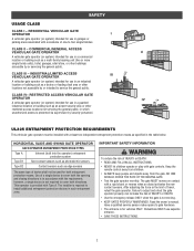
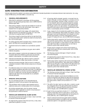
... not required to cover both directions. After adjusting the force or the limit of device shall not be installed with gate controls. CLASS III - NO ONE SHOULD CROSS THE PATH OF THE MOVING GATE. • Test the gate operator monthly. Use of INJURY or DEATH. • Use the emergency release ONLY when the gate is for both entrapment protection means. RESIDENTIAL VEHICULAR GATE OPERATOR I - IMPORTANT SAFETY INFORMATION To reduce...
... not required to cover both directions. After adjusting the force or the limit of device shall not be installed with gate controls. CLASS III - NO ONE SHOULD CROSS THE PATH OF THE MOVING GATE. • Test the gate operator monthly. Use of INJURY or DEATH. • Use the emergency release ONLY when the gate is for both entrapment protection means. RESIDENTIAL VEHICULAR GATE OPERATOR I - IMPORTANT SAFETY INFORMATION To reduce...

SL3000101U Installation Manual
Page 4
... the gate operator for Exposed Rollers • Photoelectric Sensors • Screen Mesh • Vertical Posts • Instructional and Precautionary Signage 4. Specific safety features include: • Edges Sensors (contact) • Guards for entrapment protection functions shall be exercised to start. 10. Exception: Emergency access controls only accessible by building structures, natural landscaping or similar obstruction. Therefore, safety features must be installed, one component. All openings...
... the gate operator for Exposed Rollers • Photoelectric Sensors • Screen Mesh • Vertical Posts • Instructional and Precautionary Signage 4. Specific safety features include: • Edges Sensors (contact) • Guards for entrapment protection functions shall be exercised to start. 10. Exception: Emergency access controls only accessible by building structures, natural landscaping or similar obstruction. Therefore, safety features must be installed, one component. All openings...
SL3000101U Installation Manual
Page 5
... open and fully closed position, shall not exceed 2 1/4 inches (57 mm), refer to ASTM F2200 for pedestrian access and to vehicular gates not to be automated. 2.3 Any existing automated gate, when the operator requires replacement, shall be upgraded to conform to the provisions of this specification. 2.2 This specification shall not apply to gates generally used for Exception. 3.1.4 Positive stops shall be required to limit travel...
... open and fully closed position, shall not exceed 2 1/4 inches (57 mm), refer to ASTM F2200 for pedestrian access and to vehicular gates not to be automated. 2.3 Any existing automated gate, when the operator requires replacement, shall be upgraded to conform to the provisions of this specification. 2.2 This specification shall not apply to gates generally used for Exception. 3.1.4 Positive stops shall be required to limit travel...
SL3000101U Installation Manual
Page 7
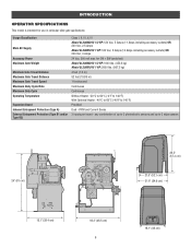
... Supply Accessory Power Maximum Gate Weight Minimum Gate Travel Distance Maximum Gate Travel Distance Maximum Gate Travel Speed Maximum Daily Cycle Rate Maximum Duty Cycle Operating Temperature Expansion Board Inherent Entrapment Protection (Type A) External Entrapment Protection (Type B1 and/or Type B2) Class I, II, III, & IV Model SL3000501U 1/2 HP: 120 Vac, 5 Amps (11 Amps including accessory outlets) OR 240 Vac, 2.5 Amps Model SL3000101U 1 HP...
... Supply Accessory Power Maximum Gate Weight Minimum Gate Travel Distance Maximum Gate Travel Distance Maximum Gate Travel Speed Maximum Daily Cycle Rate Maximum Duty Cycle Operating Temperature Expansion Board Inherent Entrapment Protection (Type A) External Entrapment Protection (Type B1 and/or Type B2) Class I, II, III, & IV Model SL3000501U 1/2 HP: 120 Vac, 5 Amps (11 Amps including accessory outlets) OR 240 Vac, 2.5 Amps Model SL3000101U 1 HP...

SL3000101U Installation Manual
Page 8
... fit specifications of the gate. Install warning signs on the side of a post or wall with safety covers on both sides of operator (refer to hit the post in certain instances. 7 To do so will cause the gate to specifications). Consider the operator placement BEFORE installing the pad or post. INTRODUCTION SITE PREPARATION Check the national and local building codes BEFORE installation. Vehicle loops are...
... fit specifications of the gate. Install warning signs on the side of a post or wall with safety covers on both sides of operator (refer to hit the post in certain instances. 7 To do so will cause the gate to specifications). Consider the operator placement BEFORE installing the pad or post. INTRODUCTION SITE PREPARATION Check the national and local building codes BEFORE installation. Vehicle loops are...

SL3000101U Installation Manual
Page 9
... control wiring MUST be located where the risk of entrapment or obstruction exists at either the opening or closing direction. Any gap larger than 2-1/4 inches between the gate and a fixed object such as a wall, pillar, column, or operator must be run in separate conduits. 8 SINGLE GATE Warning Sign Safety Catch Roller Edge Sensor Edge Sensor Photoelectric Sensors Operator DUAL GATE Earth Ground Rod Check national and local codes...
... control wiring MUST be located where the risk of entrapment or obstruction exists at either the opening or closing direction. Any gap larger than 2-1/4 inches between the gate and a fixed object such as a wall, pillar, column, or operator must be run in separate conduits. 8 SINGLE GATE Warning Sign Safety Catch Roller Edge Sensor Edge Sensor Photoelectric Sensors Operator DUAL GATE Earth Ground Rod Check national and local codes...

SL3000101U Installation Manual
Page 10
... when switch is on, heater may be a minimum of the gate (in the OPEN position). The gate operator should be installed near the front roller of the gate or near the back of 4 inches. 2. The space between the gate and the output sprocket must be hot. Lay out the concrete pad. 4"(10... cm) 24" (61 cm) 24" (61 cm) REAR INSTALLATION 4"(10 cm) 24" (61 cm) 24" (61 cm) 9 INSTALLATION • To AVOID damaging gas, power or other underground utility lines, contact underground utility locating companies BEFORE...
... when switch is on, heater may be a minimum of the gate (in the OPEN position). The gate operator should be installed near the front roller of the gate or near the back of 4 inches. 2. The space between the gate and the output sprocket must be hot. Lay out the concrete pad. 4"(10... cm) 24" (61 cm) 24" (61 cm) REAR INSTALLATION 4"(10 cm) 24" (61 cm) 24" (61 cm) 9 INSTALLATION • To AVOID damaging gas, power or other underground utility lines, contact underground utility locating companies BEFORE...

SL3000101U Installation Manual
Page 12
... of chain length. Remove the pin from the vent plug on the gear box. Connect the chain to the bottom hole in this position. 3. Vent Plug Pin REAR INSTALLATION DO NOT run the operator until instructed. The chain should not be level with the bottom idler pulley and parallel to Gate Construction Information on page 4. 1. INSTALLATION STEP 3 ATTACH THE CHAIN DO NOT run the operator until instructed. 1. Weld the rear bracket...
... of chain length. Remove the pin from the vent plug on the gear box. Connect the chain to the bottom hole in this position. 3. Vent Plug Pin REAR INSTALLATION DO NOT run the operator until instructed. The chain should not be level with the bottom idler pulley and parallel to Gate Construction Information on page 4. 1. INSTALLATION STEP 3 ATTACH THE CHAIN DO NOT run the operator until instructed. 1. Weld the rear bracket...

SL3000101U Installation Manual
Page 13
... to travel in that direction until the obstruction is every location or point of the Setup and Operation manual). If the operator does not receive the signal from a moving gate and RIGID objects, such as posts, walls, pillars, or columns. If a monitored photoelectric sensor is not working or loses power or the beam is moving gate and a stationary object. NON-CONTACT SENSORS If the photoelectric sensor beam...
... to travel in that direction until the obstruction is every location or point of the Setup and Operation manual). If the operator does not receive the signal from a moving gate and RIGID objects, such as posts, walls, pillars, or columns. If a monitored photoelectric sensor is not working or loses power or the beam is moving gate and a stationary object. NON-CONTACT SENSORS If the photoelectric sensor beam...
SL3000101U Installation Manual
Page 14
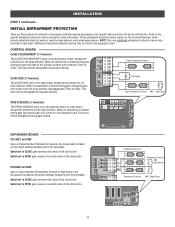
... switch settings (located next to the terminals) Switch set to CLOSE: gate reverses fully when it hits obstruction Switch set to OPEN: gate reverses 4 seconds when it hits obstruction EYE/EDGE and COM Open or Close Direction Photoelectric Sensors or Edge Sensor, the functionality is for photoelectric sensor entrapment protection for the open position and resets the Timer-toClose. Refer to OPEN: gate reverses 4 seconds when it hits obstruction OPEN CLOSE ANTENNA CURRENT MOTOR DRIVE RPM & LIMITS ALARM EXP. CONTROL BOARD CLOSE EYES/INTERRUPT (2 Terminals) The CLOSE EYES...
... switch settings (located next to the terminals) Switch set to CLOSE: gate reverses fully when it hits obstruction Switch set to OPEN: gate reverses 4 seconds when it hits obstruction EYE/EDGE and COM Open or Close Direction Photoelectric Sensors or Edge Sensor, the functionality is for photoelectric sensor entrapment protection for the open position and resets the Timer-toClose. Refer to OPEN: gate reverses 4 seconds when it hits obstruction OPEN CLOSE ANTENNA CURRENT MOTOR DRIVE RPM & LIMITS ALARM EXP. CONTROL BOARD CLOSE EYES/INTERRUPT (2 Terminals) The CLOSE EYES...
SL3000101U Installation Manual
Page 15
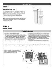
... dual gate applications, power will be returned to run in separate conduit. The power board is not grounded properly the range of maintenance the area MUST be properly grounded and connected in the area near the operator MUST NOT be performed until disconnecting the electrical power (AC or solar and battery) and locking-out the power via the operator power switch. INSTALLATION STEP 5 EARTH GROUND ROD Use the...
... dual gate applications, power will be returned to run in separate conduit. The power board is not grounded properly the range of maintenance the area MUST be properly grounded and connected in the area near the operator MUST NOT be performed until disconnecting the electrical power (AC or solar and battery) and locking-out the power via the operator power switch. INSTALLATION STEP 5 EARTH GROUND ROD Use the...

SL3000101U Installation Manual
Page 16
... grounded to the operator. Run the AC power wires to HOT using a wire nut. Connect the black wire to the junction box on the AC power switch (the AC power switch will turn the incoming 120/240 Vac power ON or OFF). 9. Ensure the wires are not pinched. 8. INSTALLATION STEP 6 continued... Connect the green wire to NEUTRAL using a wire nut. 6. Replace the junction box cover. POWER WIRING 1. Turn on the operator. 3. AC Power Switch Junction Box Junction Box Cover AMERICAN WIRE GAUGE (AWG) 14...
... grounded to the operator. Run the AC power wires to HOT using a wire nut. Connect the black wire to the junction box on the AC power switch (the AC power switch will turn the incoming 120/240 Vac power ON or OFF). 9. Ensure the wires are not pinched. 8. INSTALLATION STEP 6 continued... Connect the green wire to NEUTRAL using a wire nut. 6. Replace the junction box cover. POWER WIRING 1. Turn on the operator. 3. AC Power Switch Junction Box Junction Box Cover AMERICAN WIRE GAUGE (AWG) 14...
SL3000101U Installation Manual
Page 17
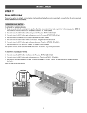
... green XMITTER LED will light. 3. BIPART DELAY 4 2 6 OPEN LEFT OPEN 8 RIGHT HANDING OPEN GND ANTENNA CURRENT MOTOR DRIVE SENSOR ID RESET RPM & LIMITS ALARM EXP. All wireless accessories will light. 3. The yellow NETWORK LED will need to assign this operator as network second. The green XMITTER LED will turn off indicating programming is successful. Both operators will beep and the yellow NETWORK LEDs will light. 6. Press and hold the LEARN button for the other operator. INSTALLATION STEP 7 DUAL GATES ONLY...
... green XMITTER LED will light. 3. BIPART DELAY 4 2 6 OPEN LEFT OPEN 8 RIGHT HANDING OPEN GND ANTENNA CURRENT MOTOR DRIVE SENSOR ID RESET RPM & LIMITS ALARM EXP. All wireless accessories will light. 3. The yellow NETWORK LED will need to assign this operator as network second. The green XMITTER LED will turn off indicating programming is successful. Both operators will beep and the yellow NETWORK LEDs will light. 6. Press and hold the LEARN button for the other operator. INSTALLATION STEP 7 DUAL GATES ONLY...
SL3000101U Installation Manual
Page 18
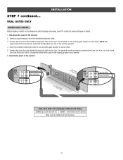
... Com Link A and Com Link B to Com Link B). Route the shielded twisted pair cable to the Com Link terminals on the primary operator. 4. DUAL GATES ONLY WIRED DUAL GATES Before digging, contact local underground utility locating companies. NOTE: We recommend that all accessories and board configurations are set on the primary gate operator control board. Connect the wires from the shielded twisted pair cable to the secondary gate operator's control board. 5. INSTALLATION...
... Com Link A and Com Link B to Com Link B). Route the shielded twisted pair cable to the Com Link terminals on the primary operator. 4. DUAL GATES ONLY WIRED DUAL GATES Before digging, contact local underground utility locating companies. NOTE: We recommend that all accessories and board configurations are set on the primary gate operator control board. Connect the wires from the shielded twisted pair cable to the secondary gate operator's control board. 5. INSTALLATION...
SL3000101U Installation Manual
Page 19
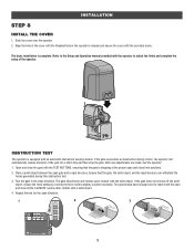
... object, reduce the force setting by turning the force control slightly counter-clockwise. SENSOR ID RESET BOARD 24 VAC IN 18 Align the hole in the cover with the threaded hole in the close limit positions. 2. Refer to the Setup and Operation manual provided with the solid object. The gate should have enough force to adjust the limits and complete the setup of the gate for the open gate and a rigid structure...
... object, reduce the force setting by turning the force control slightly counter-clockwise. SENSOR ID RESET BOARD 24 VAC IN 18 Align the hole in the cover with the threaded hole in the close limit positions. 2. Refer to the Setup and Operation manual provided with the solid object. The gate should have enough force to adjust the limits and complete the setup of the gate for the open gate and a rigid structure...
SL3000101U Installation Manual
Page 20
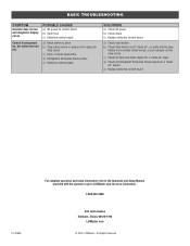
... LiftMaster.com © 2015, LiftMaster - BASIC TROUBLESHOOTING SYMPTOM Operator does not run . c) Check all Open and Close inputs for a "stuck on" input d) Check all Entrapment Protection Device inputs for a "stuck on" sensor e) Replace defective control board 01-37558 For complete operation and setup information refer to the Operation and Setup Manual provided with the operator or go to control board b) Open fuse c) Defective control board a) Reset button is a normally closed circuit, or put a jumper on . Control board powers up, but motor...
... LiftMaster.com © 2015, LiftMaster - BASIC TROUBLESHOOTING SYMPTOM Operator does not run . c) Check all Open and Close inputs for a "stuck on" input d) Check all Entrapment Protection Device inputs for a "stuck on" sensor e) Replace defective control board 01-37558 For complete operation and setup information refer to the Operation and Setup Manual provided with the operator or go to control board b) Open fuse c) Defective control board a) Reset button is a normally closed circuit, or put a jumper on . Control board powers up, but motor...


