GSD Manual
Page 4
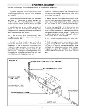
Install track hangar brackets with lockwashers and nuts though the remaining two mounting holes in the frame of the track with flatwashers under the heads and lockwashers and...carriage. 6. Install one final track hangar on the front of the carriage (see figure 3). The holes in the mounting brackets. NOTE: For Bi-parting doors, slide secondary slider carriage into track assembly first, so that the take ... carriage with the door width. Install chain take -up bolt will be mounted on the right hand end of the powerhead unit. For a right to the front idler. 4. Bolt the angle...
Install track hangar brackets with lockwashers and nuts though the remaining two mounting holes in the frame of the track with flatwashers under the heads and lockwashers and...carriage. 6. Install one final track hangar on the front of the carriage (see figure 3). The holes in the mounting brackets. NOTE: For Bi-parting doors, slide secondary slider carriage into track assembly first, so that the take ... carriage with the door width. Install chain take -up bolt will be mounted on the right hand end of the powerhead unit. For a right to the front idler. 4. Bolt the angle...

GSD Manual
Page 5
MOUNTING ASSEMBLY IDLER SHAFT ASSEMBLY ANGLE MOUNTING BRACKET FIGURE 4 HEX HEAD BOLT, 3/8-16 x 1" LONG (2 PER BRACKET) TRACK SPACER FLATWASHER, 1/8" (2 PER BRACKET) BI-PART SLIDER CARRIAGE (SEE FIGURE 2) SLIDER CARRIAGE (SEE FIGURE 1) POWERHEAD SERRATED FLANGE HEX NUT, #10 BI-PART SLIDER CARRIAGE HEX NUT, 3/8" (4 PER BRACKET) FLATWASHER, #10 (3 PER ASSEMBLY) FIGURE 5 SOCKET HEAD SCREW, 10-32 X 1-1/4" LONG (3PER ASSEMBLY) DRIVE CHAIN 5
MOUNTING ASSEMBLY IDLER SHAFT ASSEMBLY ANGLE MOUNTING BRACKET FIGURE 4 HEX HEAD BOLT, 3/8-16 x 1" LONG (2 PER BRACKET) TRACK SPACER FLATWASHER, 1/8" (2 PER BRACKET) BI-PART SLIDER CARRIAGE (SEE FIGURE 2) SLIDER CARRIAGE (SEE FIGURE 1) POWERHEAD SERRATED FLANGE HEX NUT, #10 BI-PART SLIDER CARRIAGE HEX NUT, 3/8" (4 PER BRACKET) FLATWASHER, #10 (3 PER ASSEMBLY) FIGURE 5 SOCKET HEAD SCREW, 10-32 X 1-1/4" LONG (3PER ASSEMBLY) DRIVE CHAIN 5

GSD Manual
Page 6
...Secure the assembled operator to close or 18" to the right of the track. SLIDER CARRIAGE 1-1/2" MIN. NOTE: For bi-parting doors, mount each door disconnect mechanism centered on page 2 for the door to pass between the mechanism and the door to shim the brackets out from the...for general information during this purpose. Check that the top of the installation. 1. Measure 18" to the left of the track hangers for the angle mounting brackets on large or heavy doors. 5. FIGURE 6 1" MIN. It is recommended that the disconnect pin is no more than 4 inches, it may...
...Secure the assembled operator to close or 18" to the right of the track. SLIDER CARRIAGE 1-1/2" MIN. NOTE: For bi-parting doors, mount each door disconnect mechanism centered on page 2 for the door to pass between the mechanism and the door to shim the brackets out from the...for general information during this purpose. Check that the top of the installation. 1. Measure 18" to the left of the track hangers for the angle mounting brackets on large or heavy doors. 5. FIGURE 6 1" MIN. It is recommended that the disconnect pin is no more than 4 inches, it may...

GSD Manual
Page 7
... However, a quick disconnect pin and chain mechanism is lower than the other door in the slot of chain. 11. Secure fusible link mounting bracket to upper leading edge of door (6 to itself around the weight so that the chain cannot pass through the bottom of the disconnect... (see figure 1). 3. If necessary, adjust spring on the door, directly below top of door as shown, with the slider carriage connected. Mount the chain retaining bracket (with your operator for proper synchronization. Raise the weight to the Owners Manual supplied with keyhole slot) at a convenient ...
... However, a quick disconnect pin and chain mechanism is lower than the other door in the slot of chain. 11. Secure fusible link mounting bracket to upper leading edge of door (6 to itself around the weight so that the chain cannot pass through the bottom of the disconnect... (see figure 1). 3. If necessary, adjust spring on the door, directly below top of door as shown, with the slider carriage connected. Mount the chain retaining bracket (with your operator for proper synchronization. Raise the weight to the Owners Manual supplied with keyhole slot) at a convenient ...


