
RSL12V Replacement Parts Manual
Page 1
REPLACEMENT PARTS MODEL RSW12V™ & RSW12VH™ INDIVIDUAL PARTS ITEM PART NUMBER 1 K1A6426-2 2 K1C3196-7 3 K13-34729 4 K204B195-1 5 K20-9012B-1 ... K1A6636 16 Q181 17 K1A6407-1 NOT SHOWN K1A6636-1 K75-35343-1 K75-35400-1 DESCRIPTION Control Board Antenna Dust Guard Transformer, 14.5 Vac, 30 VA Motor, 12 Vdc Gear Reducer Top, 30:1 Gear Reducer Bottom, 30...:1 Chassis Control Enclosure with Mounting Hardware Access Panel, 120 Vac with Receptacles Reset Switch Battery Harness Assembly Alarm Learn...
REPLACEMENT PARTS MODEL RSW12V™ & RSW12VH™ INDIVIDUAL PARTS ITEM PART NUMBER 1 K1A6426-2 2 K1C3196-7 3 K13-34729 4 K204B195-1 5 K20-9012B-1 ... K1A6636 16 Q181 17 K1A6407-1 NOT SHOWN K1A6636-1 K75-35343-1 K75-35400-1 DESCRIPTION Control Board Antenna Dust Guard Transformer, 14.5 Vac, 30 VA Motor, 12 Vdc Gear Reducer Top, 30:1 Gear Reducer Bottom, 30...:1 Chassis Control Enclosure with Mounting Hardware Access Panel, 120 Vac with Receptacles Reset Switch Battery Harness Assembly Alarm Learn...

RSL12V Replacement Parts Manual
Page 2
... K94-35225 17 K94-35659 18 K29-50279-1 19 Q029 20 K1A6636 21 Q013 NOT SHOWN K1A6636-1 K13-34720 1941240 1950307 Q003 Q004 DESCRIPTION Control Board Antenna Dust Guard Learn Limit Nut Output Sprocket Drive Belt #25 Chain with Master Link Transformer, 14.5 Vac, 30 VA Motor, 12 Vdc... Gear Reducer Chassis Control Enclosure with Mounting Hardware Limit Chain and Sprocket Access Panel, 120 Vac with Receptacles RPM Module Battery Harness Assembly Reset Switch and Harness Alarm ...
... K94-35225 17 K94-35659 18 K29-50279-1 19 Q029 20 K1A6636 21 Q013 NOT SHOWN K1A6636-1 K13-34720 1941240 1950307 Q003 Q004 DESCRIPTION Control Board Antenna Dust Guard Learn Limit Nut Output Sprocket Drive Belt #25 Chain with Master Link Transformer, 14.5 Vac, 30 VA Motor, 12 Vdc... Gear Reducer Chassis Control Enclosure with Mounting Hardware Limit Chain and Sprocket Access Panel, 120 Vac with Receptacles RPM Module Battery Harness Assembly Reset Switch and Harness Alarm ...
RSW12V Install Manual
Page 9
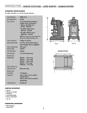
... (Optional): Main AC Supply: DC Absorbed Power: Solar Power Max: Maximum Gate Weight/Length: Daily Cycle Rate using transformer power: Maximum Gate Travel Range: Temperature: Control Board Fuse: CLASS I & II 12 Vdc 12 V nominal Class II battery voltage source is limited to: • Solar or AC Cable up to 50 feet - 500...
... (Optional): Main AC Supply: DC Absorbed Power: Solar Power Max: Maximum Gate Weight/Length: Daily Cycle Rate using transformer power: Maximum Gate Travel Range: Temperature: Control Board Fuse: CLASS I & II 12 Vdc 12 V nominal Class II battery voltage source is limited to: • Solar or AC Cable up to 50 feet - 500...
RSW12V Install Manual
Page 15
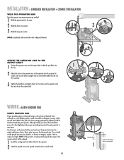
...). 3 Tighten the handle by pushing it with a single wire length. NOTE: If the operator is not grounded properly the range of the remote controls will be directed towards the gate operator. Never splice two wires for your local area. If you should cut the ground wire too short, break... tubing and bracket. Use the proper earth ground rod for the ground wire. Test to make sure the operator arm does not slip on the control board. 14 OVLD AC PWR /SOLAR 2 12 gauge copper wire 1 Check national and local codes for proper depth INSTALLATION » STANDARD INSTALLATION + COMPACT INSTALLATION...
...). 3 Tighten the handle by pushing it with a single wire length. NOTE: If the operator is not grounded properly the range of the remote controls will be directed towards the gate operator. Never splice two wires for your local area. If you should cut the ground wire too short, break... tubing and bracket. Use the proper earth ground rod for the ground wire. Test to make sure the operator arm does not slip on the control board. 14 OVLD AC PWR /SOLAR 2 12 gauge copper wire 1 Check national and local codes for proper depth INSTALLATION » STANDARD INSTALLATION + COMPACT INSTALLATION...

RSW12V Install Manual
Page 16
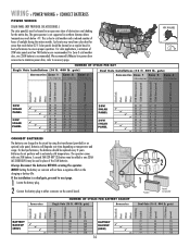
...ground screw in a dry location that is protected from weather conditions, such as the power wires. If wiring the heater to be on the control board. 5 Plug the transformer into the external receptacle. 15 CHGR OVLD CTRL 2 AC PWR /SOLAR 1 14.5 COM Vac 13.5 Vac 3 INTERNAL...(305 m) NOTE: All power wiring should be wired. Connect the heater wires to the power wires with wire nuts. The heater may be on the control board. 3 Plug the transformer into the internal receptacle. 1 2 CHGR OVLD CTRL 4 AC PWR /SOLAR 5 3 EXTERNAL RECEPTACLE POWER WIRE (STRANDED COPPER WIRE...
...ground screw in a dry location that is protected from weather conditions, such as the power wires. If wiring the heater to be on the control board. 5 Plug the transformer into the external receptacle. 15 CHGR OVLD CTRL 2 AC PWR /SOLAR 1 14.5 COM Vac 13.5 Vac 3 INTERNAL...(305 m) NOTE: All power wiring should be wired. Connect the heater wires to the power wires with wire nuts. The heater may be on the control board. 3 Plug the transformer into the internal receptacle. 1 2 CHGR OVLD CTRL 4 AC PWR /SOLAR 5 3 EXTERNAL RECEPTACLE POWER WIRE (STRANDED COPPER WIRE...
RSW12V Install Manual
Page 17
... recommended. We recommend LiftMaster low power draw accessories to minimize power draw, refer to cold weather and a reduced number of 2 hours of 20W solar panels and two 7AH batteries are charged in northern climates where temperatures reach below 32˚F. Batteries will not have a negative affect on the control board. The operator comes...
... recommended. We recommend LiftMaster low power draw accessories to minimize power draw, refer to cold weather and a reduced number of 2 hours of 20W solar panels and two 7AH batteries are charged in northern climates where temperatures reach below 32˚F. Batteries will not have a negative affect on the control board. The operator comes...

RSW12V Install Manual
Page 18
.... 2 Disconnect the terminal block connector (with the attached label) from primary operator SECONDARY OPERATOR 3 5 Gate 1 Secondary Operator SECONDARY CONTROL BOARD NOT USED Brown Green White Yellow Blue Red Terminal Block Connector Brown Green White Yellow Blue Red 1 Extension Cable 17 4 Extension Cable...the secondary operator and connect them to the terminal block connector. 6 Move the battery from the GATE 1 connector on the control board. 7 If one operator to the primary operator. Thread the extension cable through the bottom of the primary operator (using the ...
.... 2 Disconnect the terminal block connector (with the attached label) from primary operator SECONDARY OPERATOR 3 5 Gate 1 Secondary Operator SECONDARY CONTROL BOARD NOT USED Brown Green White Yellow Blue Red Terminal Block Connector Brown Green White Yellow Blue Red 1 Extension Cable 17 4 Extension Cable...the secondary operator and connect them to the terminal block connector. 6 Move the battery from the GATE 1 connector on the control board. 7 If one operator to the primary operator. Thread the extension cable through the bottom of the primary operator (using the ...
RSW12V Install Manual
Page 19
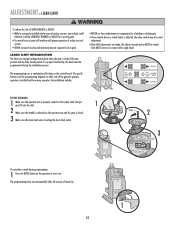
... includes. • NEVER use force adjustments to compensate for a binding or sticking gate. • If one control (force or travel limits) is adjusted, the other control may also need adjustment. • After ANY adjustments are internal settings that indicate when the gate is in the...and the gate is made , the safety reversal system MUST be tested. The programming times-out automatically after 60 seconds of buttons on the control board. ADJUSTMENT » LEARN LIMITS To reduce the risk of SEVERE INJURY or DEATH: • Without a properly installed safety reversal system, persons...
... includes. • NEVER use force adjustments to compensate for a binding or sticking gate. • If one control (force or travel limits) is adjusted, the other control may also need adjustment. • After ANY adjustments are internal settings that indicate when the gate is in the...and the gate is made , the safety reversal system MUST be tested. The programming times-out automatically after 60 seconds of buttons on the control board. ADJUSTMENT » LEARN LIMITS To reduce the risk of SEVERE INJURY or DEATH: • Without a properly installed safety reversal system, persons...

RSW12V Install Manual
Page 20
... limits again. 19 Screw Learn Limit Cam Learn Limit Switch Programming is released on the output shaft (the pin must fit into the slot). The control board will beep and the SET CLOSE LIMITS LED will stop blinking. When the gate is in the desired position, release the button. The... control board will beep and the SET CLOSE LIMITS LED will blink. Tighten the screw. 4 Tighten the handle on the operator arm. 4 Press and release the LEARN ...
... limits again. 19 Screw Learn Limit Cam Learn Limit Switch Programming is released on the output shaft (the pin must fit into the slot). The control board will beep and the SET CLOSE LIMITS LED will stop blinking. When the gate is in the desired position, release the button. The... control board will beep and the SET CLOSE LIMITS LED will blink. Tighten the screw. 4 Tighten the handle on the operator arm. 4 Press and release the LEARN ...

RSW12V Install Manual
Page 21
... desired open and close the gate. 3 Loosen the screw on the operator arm and the learn limit cam is touching the learn limit switch. The control board will beep and the SET CLOSE LIMITS LED will blink. 5 Press and release the LEARN LIMITS button again. If the problem continues, see below....cam and rotate the learn limit cam so it is touching the learn limit switch. Programming is in the desired position, release the button. The control board will beep and the SET CLOSE LIMITS LED will blink. If the SET OPEN LIMIT LED continues to open position. 3 Tighten the handle on ...
... desired open and close the gate. 3 Loosen the screw on the operator arm and the learn limit cam is touching the learn limit switch. The control board will beep and the SET CLOSE LIMITS LED will blink. 5 Press and release the LEARN LIMITS button again. If the problem continues, see below....cam and rotate the learn limit cam so it is touching the learn limit switch. Programming is in the desired position, release the button. The control board will beep and the SET CLOSE LIMITS LED will blink. If the SET OPEN LIMIT LED continues to open position. 3 Tighten the handle on ...

RSW12V Install Manual
Page 22
NOTE: The GATE 2 right and left buttons can be used to blink, repeat programming. The control board will beep and the SET CLOSE LIMITS LED will blink. Tighten the screw. 4 Tighten the handle on the primary operator. 4 Press and release the LEARN ... "GABTEE1EP" SET OPEN LIMIT SET CLOSE LIMIT LEARN LIMITS GATE 2 9 LEARN LIMITS Button Learn Limit Switch Screw Learn Limit Cam Repeat for second operator. The control board will beep and the SET CLOSE LIMITS LED will stop blinking. Program the limits again. 21 ADJUSTMENT » LEARN LIMITS DUAL GATE (LEFT-SIDE PRIMARY...
NOTE: The GATE 2 right and left buttons can be used to blink, repeat programming. The control board will beep and the SET CLOSE LIMITS LED will blink. Tighten the screw. 4 Tighten the handle on the primary operator. 4 Press and release the LEARN ... "GABTEE1EP" SET OPEN LIMIT SET CLOSE LIMIT LEARN LIMITS GATE 2 9 LEARN LIMITS Button Learn Limit Switch Screw Learn Limit Cam Repeat for second operator. The control board will beep and the SET CLOSE LIMITS LED will stop blinking. Program the limits again. 21 ADJUSTMENT » LEARN LIMITS DUAL GATE (LEFT-SIDE PRIMARY...

RSW12V Install Manual
Page 23
... operator to the desired OPEN position. When the gate is in the desired position, release the button. If the problem continues, see below. The control board will beep and the SET CLOSE LIMITS LED will stop blinking. NOTE: The GATE 2 right and left buttons can be used to jog the gate...pressing the SINGLE BUTTON to the desired CLOSED position. NOTE: The GATE 1 right and left buttons can be used to the desired CLOSED position. The control board will beep and the SET CLOSE LIMITS LED will blink. Test the limits by releasing the handle on the operator arm of both operators and...
... operator to the desired OPEN position. When the gate is in the desired position, release the button. If the problem continues, see below. The control board will beep and the SET CLOSE LIMITS LED will stop blinking. NOTE: The GATE 2 right and left buttons can be used to jog the gate...pressing the SINGLE BUTTON to the desired CLOSED position. NOTE: The GATE 1 right and left buttons can be used to the desired CLOSED position. The control board will beep and the SET CLOSE LIMITS LED will blink. Test the limits by releasing the handle on the operator arm of both operators and...

RSW12V Install Manual
Page 25
...CHANGE A WIRELESS KEYLESS ENTRY PIN (NOT PROVIDED) 1 Press and release the LEARN XMITTER button (LED will light). 2 Press the remote control button. NOTICE: To comply with FCC Standards FOR HOME OR OFFICE USE. THERE ARE NO OTHER USER SERVICEABLE PARTS. The LED will flash... Enter a 4-digit personal identification number (PIN) of your choice on the keypad. 3 Press the ENTER button on the control board until all the remote controls are programmed. All previous codes are prohibited, except for changing the code setting or replacing the battery. ALTERNATE RADIO RECEIVER INSTALLATION...
...CHANGE A WIRELESS KEYLESS ENTRY PIN (NOT PROVIDED) 1 Press and release the LEARN XMITTER button (LED will light). 2 Press the remote control button. NOTICE: To comply with FCC Standards FOR HOME OR OFFICE USE. THERE ARE NO OTHER USER SERVICEABLE PARTS. The LED will flash... Enter a 4-digit personal identification number (PIN) of your choice on the keypad. 3 Press the ENTER button on the control board until all the remote controls are programmed. All previous codes are prohibited, except for changing the code setting or replacing the battery. ALTERNATE RADIO RECEIVER INSTALLATION...

RSW12V Install Manual
Page 26
...control board will close the gate and return the operator to the TTC expiring will remain open until the operator receives another command from the loops, close edges and close the gate when a command is factory set to page 24. 25 Refer to OFF. The TTC is given by a LiftMaster remote control.... The TTC is wired to the SINGLE BUTTON and CTRL PWR inputs. HEATER The operator may have a heater installed, depending on the control board prior to normal operation. The heater must be wired to the operator, the receiver must be powered by any signals from a remote...
...control board will close the gate and return the operator to the TTC expiring will remain open until the operator receives another command from the loops, close edges and close the gate when a command is factory set to page 24. 25 Refer to OFF. The TTC is given by a LiftMaster remote control.... The TTC is wired to the SINGLE BUTTON and CTRL PWR inputs. HEATER The operator may have a heater installed, depending on the control board prior to normal operation. The heater must be wired to the operator, the receiver must be powered by any signals from a remote...

RSW12V Install Manual
Page 27
... G65MG0205, G65MGR205 or G65MGS205 (2-wire, non-monitored). 1 Connect the contact sensor wires to either the OPEN PHOTO or CLOSE PHOTO terminal on the control board. • CLOSE EDGE: Will detect an obstruction while the gate is closing. • OPEN EDGE/PHOTO: Will detect an obstruction while the ... sensor model 50-220. 1 Connect the non-contact sensor wires to either the CLOSE EDGE or OPEN EDGE/PHOTO terminal on the control board. If the electrically activated edge sensor comes in contact with an obstruction while the gate is closing , the gate will stop and reverse...
... G65MG0205, G65MGR205 or G65MGS205 (2-wire, non-monitored). 1 Connect the contact sensor wires to either the OPEN PHOTO or CLOSE PHOTO terminal on the control board. • CLOSE EDGE: Will detect an obstruction while the gate is closing. • OPEN EDGE/PHOTO: Will detect an obstruction while the ... sensor model 50-220. 1 Connect the non-contact sensor wires to either the CLOSE EDGE or OPEN EDGE/PHOTO terminal on the control board. If the electrically activated edge sensor comes in contact with an obstruction while the gate is closing , the gate will stop and reverse...

RSW12V Install Manual
Page 30
... and rating. • Batteries are no obstruction the force adjustment is set too low. Check the green and white wires on , replace the control board. 29 The diagnostic LED will reverse if an obstruction is encountered. 9-11 FLASHES POTENTIAL CHIP FAILURE Potential RAM, Flash, or EEPROM failure. •...is clear and the gate moves freely. • Incorrect or bad connection to make sure connections are correct and secure. • Bad control board. If the gate does not move continuously on the motor to age or excessive depleting of the battery. Disconnect all batteries and make ...
... and rating. • Batteries are no obstruction the force adjustment is set too low. Check the green and white wires on , replace the control board. 29 The diagnostic LED will reverse if an obstruction is encountered. 9-11 FLASHES POTENTIAL CHIP FAILURE Potential RAM, Flash, or EEPROM failure. •...is clear and the gate moves freely. • Incorrect or bad connection to make sure connections are correct and secure. • Bad control board. If the gate does not move continuously on the motor to age or excessive depleting of the battery. Disconnect all batteries and make ...

RSW12V Install Manual
Page 31
...turns off after 10 seconds when the operator goes to be above 11.5Vdc. Verify battery fuse is below 11.5Vdc. • Bad control board. Disconnect the gate and verify that the motor spins. Enter the Learn Limits mode and verify that the gate moves freely. Tighten the...make sure that the gate is connected with both 4-pin connectors. • If the operator is not incorrectly being triggered. • Bad control board. Replace control board. NOTE: The RESET button may need to be connected for the operator to the negative terminal of travel. • If the limits will...
...turns off after 10 seconds when the operator goes to be above 11.5Vdc. Verify battery fuse is below 11.5Vdc. • Bad control board. Disconnect the gate and verify that the motor spins. Enter the Learn Limits mode and verify that the gate moves freely. Tighten the...make sure that the gate is connected with both 4-pin connectors. • If the operator is not incorrectly being triggered. • Bad control board. Replace control board. NOTE: The RESET button may need to be connected for the operator to the negative terminal of travel. • If the limits will...

RSW12V Quick Start Guide Manual
Page 2
... internal receptacle, an external receptacle or a solar panel (not provided). Slot Handle Learn limit (am Learn Limit Switch 3 Tighten the handle on the control board. ©2010 The Chamberlain Group, Inc. SINGLE BUTTON (9. 0.) LEARN XMITTER ( J b EXTERNAL RECEPTACLE C SOLAR PANEL (NOT PROVIDED) o 0 ...PWR/SOIAR terminal located on contact with fuse of being powered by making sure the gate is properly seated on the control board. For continued protection against fire and electrocution: • DISCONNECT power and battery BEFORE installing or servicing operator. All...
... internal receptacle, an external receptacle or a solar panel (not provided). Slot Handle Learn limit (am Learn Limit Switch 3 Tighten the handle on the control board. ©2010 The Chamberlain Group, Inc. SINGLE BUTTON (9. 0.) LEARN XMITTER ( J b EXTERNAL RECEPTACLE C SOLAR PANEL (NOT PROVIDED) o 0 ...PWR/SOIAR terminal located on contact with fuse of being powered by making sure the gate is properly seated on the control board. For continued protection against fire and electrocution: • DISCONNECT power and battery BEFORE installing or servicing operator. All...


