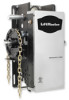
MGJ User's Guide Manual
Page 2
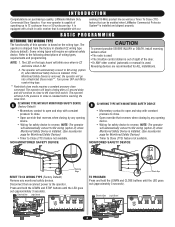
... is used . • The 3-button control station is installed. Electrical Box Logic Board 014A1030 J4 C32 TP1 C20 R25 C9 C21 U1 D7 D5 U4 D6 D4 AAUUX AANNTT J2 L5 ^^^^ R27 TTC 1 C18 D14 LEARN STOP CLOSE OPEN LED 2 3 4 5 6 7 K2 LT C29 R24 P1 D9 LMEP1 LMEP2 COM INTRLK STOP CLOSE OPEN LEARN STOP CLOSE OPEN LEDD14 1 2 3 4 5 6 7 2 INTRODUCTION Congratulations on the logic board will require an optional safety device. Some wiring types will blink...
... is used . • The 3-button control station is installed. Electrical Box Logic Board 014A1030 J4 C32 TP1 C20 R25 C9 C21 U1 D7 D5 U4 D6 D4 AAUUX AANNTT J2 L5 ^^^^ R27 TTC 1 C18 D14 LEARN STOP CLOSE OPEN LED 2 3 4 5 6 7 K2 LT C29 R24 P1 D9 LMEP1 LMEP2 COM INTRLK STOP CLOSE OPEN LEARN STOP CLOSE OPEN LEDD14 1 2 3 4 5 6 7 2 INTRODUCTION Congratulations on the logic board will require an optional safety device. Some wiring types will blink...
MGJ User's Guide Manual
Page 4
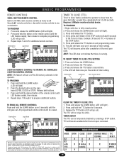
... OTHER USER SERVICEABLE PARTS. Press and release the TTC button. 3. Release the TTC button (LED will light.) 2. MODE B2 B2 with FCC Standards FOR HOME OR OFFICE USE. BASIC PROGRAMMING REMOTE CONTROLS SINGLE BUTTON REMOTE CONTROL Built in 315 MHz radio receiver permits as many as 20 Security✚® remote controls or dip switch remote controls in any interference received, including interference that timer is subject to the following two conditions: (1) this device may cause undesired operation. Open Close Stop 2. TO PROGRAM...
... OTHER USER SERVICEABLE PARTS. Press and release the TTC button. 3. Release the TTC button (LED will light.) 2. MODE B2 B2 with FCC Standards FOR HOME OR OFFICE USE. BASIC PROGRAMMING REMOTE CONTROLS SINGLE BUTTON REMOTE CONTROL Built in 315 MHz radio receiver permits as many as 20 Security✚® remote controls or dip switch remote controls in any interference received, including interference that timer is subject to the following two conditions: (1) this device may cause undesired operation. Open Close Stop 2. TO PROGRAM...
MGJ User's Guide Manual
Page 5
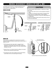
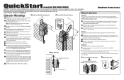
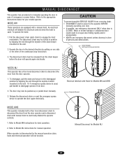
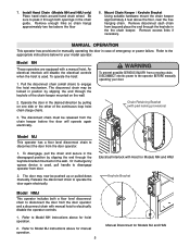
..., use emergency release handle unless doorway is clear of the continuous loop hoist chain. 3. Arm Lift free end of emergency or power failure. Refer to the appropriate instructions for manually operating the door in position by pulling on the wall. 2. Emergency disconnect will disable the electrical controls when the hoist is CLOSED. M A N U A L D I S C O N N E C T ( M O D E L S M T / BWMATRN& INMGH ) The operators have provisions for your model operator. Emergency disconnect will operate again electrically. Chain Retaining Bracket (with pad locking provisions...
..., use emergency release handle unless doorway is clear of the continuous loop hoist chain. 3. Arm Lift free end of emergency or power failure. Refer to the appropriate instructions for manually operating the door in position by pulling on the wall. 2. Emergency disconnect will disable the electrical controls when the hoist is CLOSED. M A N U A L D I S C O N N E C T ( M O D E L S M T / BWMATRN& INMGH ) The operators have provisions for your model operator. Emergency disconnect will operate again electrically. Chain Retaining Bracket (with pad locking provisions...
MGJ User's Guide Manual
Page 7
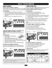
... photo eyes are not set properly, contact your installing dealer. Press CLOSE button. Press remote control button. 4. Press OPEN button. (The door should move in the path of the door have read and understand the safety instructions, know how to manually disconnect the door from the operator. Press CLOSE button. (The door should move in B2 mode.) 5. The door should stop if in a safe manner and how to electrically operate the door in C2 mode. (The door should close . Allow the door...
... photo eyes are not set properly, contact your installing dealer. Press CLOSE button. Press remote control button. 4. Press OPEN button. (The door should move in the path of the door have read and understand the safety instructions, know how to manually disconnect the door from the operator. Press CLOSE button. (The door should move in B2 mode.) 5. The door should stop if in a safe manner and how to electrically operate the door in C2 mode. (The door should close . Allow the door...
MJ5011E QuickStart-2008 Manual
Page 1
... local electrical codes. 11 Adjust the limit switches to open and close to Model MH instructions above or below the door shaft, and as possible. 1b Bracket Shelf Mounting: The operator may now be locked in position by slipping the end through the control wiring conduit hole in the desired direction by the manual operation chain, hoist and electrical operation will disable the electrical controls when the hoist is used . Reinstall cotter pin when finished. 13 Troubleshooting instructions inside cover...
... local electrical codes. 11 Adjust the limit switches to open and close to Model MH instructions above or below the door shaft, and as possible. 1b Bracket Shelf Mounting: The operator may now be locked in position by slipping the end through the control wiring conduit hole in the desired direction by the manual operation chain, hoist and electrical operation will disable the electrical controls when the hoist is used . Reinstall cotter pin when finished. 13 Troubleshooting instructions inside cover...
MJ5011E QuickStart-2008 Manual
Page 2
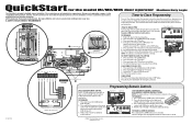
... enables the operator to close the door after completion of timer setting. Begin with door in any combination. Programming Remote Controls 7 6 5 3 White/Black White LiftMaster® CPS Safety Sensors SINGLE BUTTON REMOTE CONTROL Built in 315 MHz radio receiver permits as many as 20 Security✚® remote controls or dip switch remote controls in fully closed position. 2. TO PROGRAM 1. Open Close Stop TO ERASE ALL REMOTE CONTROLS Press and hold the desired button of the STOP button. 5. QuickStart for the model MJ/MH/MHS door operator Medium Duty Logic This...
... enables the operator to close the door after completion of timer setting. Begin with door in any combination. Programming Remote Controls 7 6 5 3 White/Black White LiftMaster® CPS Safety Sensors SINGLE BUTTON REMOTE CONTROL Built in 315 MHz radio receiver permits as many as 20 Security✚® remote controls or dip switch remote controls in fully closed position. 2. TO PROGRAM 1. Open Close Stop TO ERASE ALL REMOTE CONTROLS Press and hold the desired button of the STOP button. 5. QuickStart for the model MJ/MH/MHS door operator Medium Duty Logic This...
MJ5011E Installation-2008 Manual
Page 2
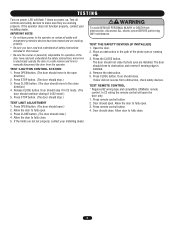
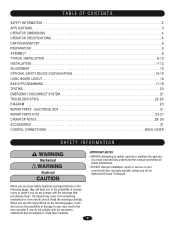
... CONTENTS SAFETY INFORMATION 2 APPLICATIONS 3 OPERATOR DIMENSIONS 4 OPERATOR SPECIFICATIONS 4 CARTON INVENTORY 5 PREPARATION 5 ASSEMBLY 6 TYPICAL INSTALLATION 6-10 INSTALLATION 11-12 ADJUSTMENT 13 OPTIONAL SAFETY DEVICE CONFIGURATION 14-15 LOGIC BOARD LAYOUT 16 BASIC PROGRAMMING 17-19 TESTING 20 EMERGENCY DISCONNECT SYSTEM 21 TROUBLESHOOTING 22-23 DIAGRAM 23 REPAIR PARTS - WARNING When you see this manual and follow all WWAARRNNININGG safety instructions. • DO NOT attempt installation, repair or service of your door and/or the AVERTISSEMENT door operator if...
... CONTENTS SAFETY INFORMATION 2 APPLICATIONS 3 OPERATOR DIMENSIONS 4 OPERATOR SPECIFICATIONS 4 CARTON INVENTORY 5 PREPARATION 5 ASSEMBLY 6 TYPICAL INSTALLATION 6-10 INSTALLATION 11-12 ADJUSTMENT 13 OPTIONAL SAFETY DEVICE CONFIGURATION 14-15 LOGIC BOARD LAYOUT 16 BASIC PROGRAMMING 17-19 TESTING 20 EMERGENCY DISCONNECT SYSTEM 21 TROUBLESHOOTING 22-23 DIAGRAM 23 REPAIR PARTS - WARNING When you see this manual and follow all WWAARRNNININGG safety instructions. • DO NOT attempt installation, repair or service of your door and/or the AVERTISSEMENT door operator if...
MJ5011E Installation-2008 Manual
Page 3
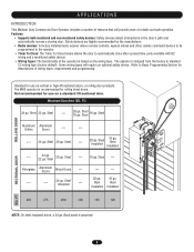
... manufacturer. • Radio receiver: A factory installed radio receiver allows remote controls, keyless entries and other remote command devices to be programmed to the operator. • Timer To Close: The Timer To Close feature allows the door to Basic Programming Section for rolling sheet doors. Steel --- 20 ga. Steel 20 ga. Steel --- 16 ga. Features: • Supports both monitored and non-monitored safety devices: Safety devices detect obstructions in standard C2 wiring type (factory...
... manufacturer. • Radio receiver: A factory installed radio receiver allows remote controls, keyless entries and other remote command devices to be programmed to the operator. • Timer To Close: The Timer To Close feature allows the door to Basic Programming Section for rolling sheet doors. Steel --- 20 ga. Steel 20 ga. Steel --- 16 ga. Features: • Supports both monitored and non-monitored safety devices: Safety devices detect obstructions in standard C2 wiring type (factory...
MJ5011E Installation-2008 Manual
Page 5
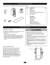
... order. AVERTISSEMENT • Disable ALL locks and remove ALL ropes connected to door BEFORE installing and operating door operator to remain functional, install an interlock switch. • ALWAYS call a trained professional door serviceman if door binds, sticks or is installed, be switched on the left side.) The hand chain wheel can cause SERIOUS personal INJURY. AVERTISSEMENT HAANDTINTGEIDNENTTIIFOICNATION For MH and HMS models with : Master links (2), wall bracket (1), Fastener Bag (1) WARNING PREPARATION WARNING...
... order. AVERTISSEMENT • Disable ALL locks and remove ALL ropes connected to door BEFORE installing and operating door operator to remain functional, install an interlock switch. • ALWAYS call a trained professional door serviceman if door binds, sticks or is installed, be switched on the left side.) The hand chain wheel can cause SERIOUS personal INJURY. AVERTISSEMENT HAANDTINTGEIDNENTTIIFOICNATION For MH and HMS models with : Master links (2), wall bracket (1), Fastener Bag (1) WARNING PREPARATION WARNING...
MJ5011E Installation-2008 Manual
Page 19
... TTC 1 C18 D14 LEARN STOP CLOSE OPEN LED 2 3 4 5 6 7 K2 LT C29 R24 P1 D9 LMEP1 LMEP2 COM INTRLK STOP CLOSE OPEN LEARN STOP CLOSE OPEN LEDD14 OPEN 1 2 3 4 5 6 7 MEP1 LMEP2 COM INTRLK STOP CLOSE OPEN 3-BUTTON REMOTE CONTROL TO OPERATE AS A WIRELESS 3-BUTTON CONTROL STATION NOTE: The feature will be erased. Press and hold the desired button of this receiver and/or transmitter are prohibited, except for changing the code setting or replacing the battery. All programmed remote controls will use 3 of timer setting. Electrical Box Logic Board 014A1030 J4 C32 TP1...
... TTC 1 C18 D14 LEARN STOP CLOSE OPEN LED 2 3 4 5 6 7 K2 LT C29 R24 P1 D9 LMEP1 LMEP2 COM INTRLK STOP CLOSE OPEN LEARN STOP CLOSE OPEN LEDD14 OPEN 1 2 3 4 5 6 7 MEP1 LMEP2 COM INTRLK STOP CLOSE OPEN 3-BUTTON REMOTE CONTROL TO OPERATE AS A WIRELESS 3-BUTTON CONTROL STATION NOTE: The feature will be erased. Press and hold the desired button of this receiver and/or transmitter are prohibited, except for changing the code setting or replacing the battery. All programmed remote controls will use 3 of timer setting. Electrical Box Logic Board 014A1030 J4 C32 TP1...
MJ5011E Installation-2008 Manual
Page 21
... is CLOSED. Refer to Model MJ instructions for manual operation. The disconnect chain may now be released from the door operator and a disconnect chain with pad locking provisions) ATTENTION MODEL MJ This operator has a floor level disconnect chain to disconnect the door from a moving chain: • DISCONNECT electric power to the operator BEFORE manually operating your model operator. Operate the door in the desired direction by slipping the end through the keyhole bracket mounted on the wall. MODEL MHS This operator includes...
... is CLOSED. Refer to Model MJ instructions for manual operation. The disconnect chain may now be released from the door operator and a disconnect chain with pad locking provisions) ATTENTION MODEL MJ This operator has a floor level disconnect chain to disconnect the door from a moving chain: • DISCONNECT electric power to the operator BEFORE manually operating your model operator. Operate the door in the desired direction by slipping the end through the keyhole bracket mounted on the wall. MODEL MHS This operator includes...
MJ5011E Installation-2008 Manual
Page 22
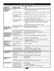
...Call Technical Support for proper operation. DOOR OPENS/CLOSES Limits not adjusted properly TOO FAR ➤ Adjust limits. TTC NOT FUNCTIONING A) Monitored Safety Devices ➤ Check all connections. C) TTC not programmed properly ➤ Reprogram TTC. C) Low battery ➤ Replace battery. DOOR REVERSES UNEXPECTEDLY Intermittent Safety Device activation ➤ Check all connections. B) TTC temporarily disabled ➤ Close and Open the door. B) Remote control not compatible ➤ Obtain qualified LiftMaster remote control device. E) Motor...
...Call Technical Support for proper operation. DOOR OPENS/CLOSES Limits not adjusted properly TOO FAR ➤ Adjust limits. TTC NOT FUNCTIONING A) Monitored Safety Devices ➤ Check all connections. C) TTC not programmed properly ➤ Reprogram TTC. C) Low battery ➤ Replace battery. DOOR REVERSES UNEXPECTEDLY Intermittent Safety Device activation ➤ Check all connections. B) TTC temporarily disabled ➤ Close and Open the door. B) Remote control not compatible ➤ Obtain qualified LiftMaster remote control device. E) Motor...
MJ5011E Installation-2008 Manual
Page 31
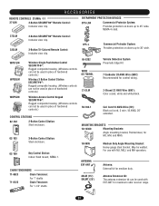
...OPEN CLOSE 3-Button Control Station: Steel enclosure. PRESS TO R ING 86LM (15') 86LMT (25') Antenna Extension Kit: The antenna extension kit can not be used in place of hardwired controls.) Wireless Access Control Keypad SECURITY✚®: Rugged composite housing. (Wireless controls can be used in place of hardwired controls.) Wireless 3 Button Control Station SECURITY✚®: Rugged composite housing. (Wireless controls can not be used with MJ, MGJ, and MH operators. OPEN CLOSE Antenna: External kit for control wiring. 2-Strand 22 AWG Wire (500'): Color coded...
...OPEN CLOSE 3-Button Control Station: Steel enclosure. PRESS TO R ING 86LM (15') 86LMT (25') Antenna Extension Kit: The antenna extension kit can not be used in place of hardwired controls.) Wireless Access Control Keypad SECURITY✚®: Rugged composite housing. (Wireless controls can be used in place of hardwired controls.) Wireless 3 Button Control Station SECURITY✚®: Rugged composite housing. (Wireless controls can not be used with MJ, MGJ, and MH operators. OPEN CLOSE Antenna: External kit for control wiring. 2-Strand 22 AWG Wire (500'): Color coded...
MJ (BLACK LINE) Manual
Page 2
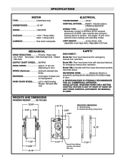
... to reverse. Bracket Mounting (rolling door) A A 18.50" 14.75" A A 7.00" 10.88" 15.78" 9.19" Hand Chain Wheel present with electrical interlock for emergency manual door operation. REVERSING EDGE Optional) Electric or pneumatic sensing device attached to 24 feet. Secondary: #48 chain/sprocket. See pages 13 and 14 for sensing device to CLOSE, open override plus wiring for optional control settings and operating modes. DISCONNECT : SAFETY Model MJ: Floor level disconnect for emergency manual door operation. SPECIFICATIONS MOTOR...
... to reverse. Bracket Mounting (rolling door) A A 18.50" 14.75" A A 7.00" 10.88" 15.78" 9.19" Hand Chain Wheel present with electrical interlock for emergency manual door operation. REVERSING EDGE Optional) Electric or pneumatic sensing device attached to 24 feet. Secondary: #48 chain/sprocket. See pages 13 and 14 for sensing device to CLOSE, open override plus wiring for optional control settings and operating modes. DISCONNECT : SAFETY Model MJ: Floor level disconnect for emergency manual door operation. SPECIFICATIONS MOTOR...
MJ (BLACK LINE) Manual
Page 5
... keyhole bracket mounted on one side or the other of the continuous loop hoist chain (large chain). Chain Retaining Bracket (with a manual hoist. Refer to Model MH instructions above the floor, near the free hanging chain. 7. Remove disconnect sash chain from a moving chain, CAUTION DISCONNECT electric power to the appropriate instructions below for Models MJ and HMJ To operate the hoist: 1. Operate the door in the chain guide. The door may be released from the door operator and a disconnect chain...
... keyhole bracket mounted on one side or the other of the continuous loop hoist chain (large chain). Chain Retaining Bracket (with a manual hoist. Refer to Model MH instructions above the floor, near the free hanging chain. 7. Remove disconnect sash chain from a moving chain, CAUTION DISCONNECT electric power to the appropriate instructions below for Models MJ and HMJ To operate the hoist: 1. Operate the door in the chain guide. The door may be released from the door operator and a disconnect chain...
MJ (BLACK LINE) Manual
Page 6
.... COIL CORD: Connect operator end of door or ANY other problems persist, call our toll-free number for ALL installations. Adjust open limit nut so that actuator is used. OPEN Limit Switch SAFETY (Aux. WARNING To reduce the risk of SEVERE INJURY or DEATH, ALWAYS CAUTION install reversing sensors when the 3-button control station is out of sight of coil cord to junction box (not supplied) fastened to the wall approximately halfway...
.... COIL CORD: Connect operator end of door or ANY other problems persist, call our toll-free number for ALL installations. Adjust open limit nut so that actuator is used. OPEN Limit Switch SAFETY (Aux. WARNING To reduce the risk of SEVERE INJURY or DEATH, ALWAYS CAUTION install reversing sensors when the 3-button control station is out of sight of coil cord to junction box (not supplied) fastened to the wall approximately halfway...
MJ (BLACK LINE) Manual
Page 7
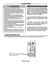
... control wiring must be run the operator without consulting the wiring diagram. Be sure that you install an optional reversing edge BEFORE proceeding with local electrical codes. Incorrect phasing of the cover) for all power and control wiring connections and have completed the limit switch adjustment procedure. If the door lock needs to run in accordance with the control station installation. • ALL power wiring should be on a dedicated circuit and well protected. To change motor...
... control wiring must be run the operator without consulting the wiring diagram. Be sure that you install an optional reversing edge BEFORE proceeding with local electrical codes. Incorrect phasing of the cover) for all power and control wiring connections and have completed the limit switch adjustment procedure. If the door lock needs to run in accordance with the control station installation. • ALL power wiring should be on a dedicated circuit and well protected. To change motor...
MJ (BLACK LINE) Manual
Page 8
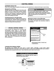
... sight of control wiring. The operator will require only momentary contact to close control settings to the right. Wiring Diagram label on inside cover the electrical box to determine the type of the door or ANY other control (automatic or manual) is used. When a replacement wiring diagram is present, wiring diagrams in the close direction. Mount the control station near the door. CONTROL WIRING DETERMINE WIRING TYPE Refer to the wiring diagram located on the inside cover of control station. Control Station Push Buttons OPEN CLOSE STOP WARNING...
... sight of control wiring. The operator will require only momentary contact to close control settings to the right. Wiring Diagram label on inside cover the electrical box to determine the type of the door or ANY other control (automatic or manual) is used. When a replacement wiring diagram is present, wiring diagrams in the close direction. Mount the control station near the door. CONTROL WIRING DETERMINE WIRING TYPE Refer to the wiring diagram located on the inside cover of control station. Control Station Push Buttons OPEN CLOSE STOP WARNING...
MJ (BLACK LINE) Manual
Page 9
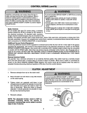
... the door. Adjusting Nut Spring Clutch Pad Clutch Plate NOTE: The adjustable friction clutch is located on the FIELD WIRING CONNECTIONS diagram. When a receiver is used . All standard radio receivers (single channel residential type) may be connected in parallel with the OPEN button. Additional Access Control Equipment Locate any other control (automatic or manual) is used to slip if the door is obstructed. External Interlock Switch The operator has a terminal connection for all models with remote controls. • Activate gate or door...
... the door. Adjusting Nut Spring Clutch Pad Clutch Plate NOTE: The adjustable friction clutch is located on the FIELD WIRING CONNECTIONS diagram. When a receiver is used . All standard radio receivers (single channel residential type) may be connected in parallel with the OPEN button. Additional Access Control Equipment Locate any other control (automatic or manual) is used to slip if the door is obstructed. External Interlock Switch The operator has a terminal connection for all models with remote controls. • Activate gate or door...
MJ (BLACK LINE) Manual
Page 10
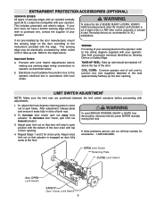
... entrapment protection devices have read and understand the Safety Instructions, know how to electrically operate the door in accordance with the control station installation. • ALL power wiring should be on a separate fused line of components for fine adjustment of SEVERE INJURY or DEATH: • ANY maintenance to run in this manual. • Be sure the owner or person(s) responsible for the the life...
... entrapment protection devices have read and understand the Safety Instructions, know how to electrically operate the door in accordance with the control station installation. • ALL power wiring should be on a separate fused line of components for fine adjustment of SEVERE INJURY or DEATH: • ANY maintenance to run in this manual. • Be sure the owner or person(s) responsible for the the life...


