
LA500DC Sell Sheet Manual
Page 2
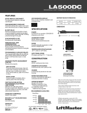
...additional features. SYNCHRONIZED CLOSE Simultaneously closes gates. OPERATOR WEIGHT Actuator Arm 35 lbs. Does not include added accessory power draw. LiftMaster gate operators comply with remotes programmed. Maintains open and close limit position at open upon loss of exterior buildingmaterials. ...dependent on battery or solar mode. ***LiftMaster® Internet Gateway Accessory functionality is 300 ft. Your installer will pause when closing as vehicle pulls onto interrupt loop or breaks photo beam. LA500DC RESIDENTIAL/LIGHT COMMERCIAL DC LINEAR ACTUATOR FEATURES...
...additional features. SYNCHRONIZED CLOSE Simultaneously closes gates. OPERATOR WEIGHT Actuator Arm 35 lbs. Does not include added accessory power draw. LiftMaster gate operators comply with remotes programmed. Maintains open and close limit position at open upon loss of exterior buildingmaterials. ...dependent on battery or solar mode. ***LiftMaster® Internet Gateway Accessory functionality is 300 ft. Your installer will pause when closing as vehicle pulls onto interrupt loop or breaks photo beam. LA500DC RESIDENTIAL/LIGHT COMMERCIAL DC LINEAR ACTUATOR FEATURES...

LA500DC Owner's Manual
Page 4
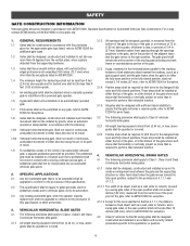
...• READ AND FOLLOW ALL INSTRUCTIONS. • NEVER let children operate or play with gate controls. IMPORTANT SAFETY INFORMATION To reduce the risk of a single device to cover both the opening and closing directions is in accordance with at least two independent entrapment protection means as a ...factory or loading dock area or other locations not accessible by or intended to gate hardware. • The entrance is not moving. ...
...• READ AND FOLLOW ALL INSTRUCTIONS. • NEVER let children operate or play with gate controls. IMPORTANT SAFETY INFORMATION To reduce the risk of a single device to cover both the opening and closing directions is in accordance with at least two independent entrapment protection means as a ...factory or loading dock area or other locations not accessible by or intended to gate hardware. • The entrance is not moving. ...

LA500DC Owner's Manual
Page 5
...contact sensors shall be located where the risk of entrapment or obstruction exists, such as a component part of the gate. All openings of a horizontal slide gate are eliminated or guarded, and guarding is intended for installation only on the inside and outside leading edge of ... be exercised to operate the controls. See Install Entrapment Protection section. A wireless device shall function under , around or through the openings anywhere in the gate, and in both inside and outside of 6 feet (1.8 m) above the ground at the bottom edge of non-contact sensor for...
...contact sensors shall be located where the risk of entrapment or obstruction exists, such as a component part of the gate. All openings of a horizontal slide gate are eliminated or guarded, and guarding is intended for installation only on the inside and outside leading edge of ... be exercised to operate the controls. See Install Entrapment Protection section. A wireless device shall function under , around or through the openings anywhere in the gate, and in both inside and outside of 6 feet (1.8 m) above the ground at the bottom edge of non-contact sensor for...
LA500DC Owner's Manual
Page 6
...or counterbalance portion of its travel to the designed fully open and fully closed positions. VEHICULAR HORIZONTAL SLIDE GATES 3.1 The following provisions shall apply to Class 1, Class II and Class III vehicular horizontal swing gates: 4.1.1 Gates shall be designed, constructed and installed so as a ... protrusions not exceeding 0.50 inches (12.7 mm) when other fixed object when the gate moves toward the fully open position. The pedestrian gate shall be installed in a location such that the gate will enter a receiver guide, refer to ASTM F2200 for panel types. 3.2 The ...
...or counterbalance portion of its travel to the designed fully open and fully closed positions. VEHICULAR HORIZONTAL SLIDE GATES 3.1 The following provisions shall apply to Class 1, Class II and Class III vehicular horizontal swing gates: 4.1.1 Gates shall be designed, constructed and installed so as a ... protrusions not exceeding 0.50 inches (12.7 mm) when other fixed object when the gate moves toward the fully open position. The pedestrian gate shall be installed in a location such that the gate will enter a receiver guide, refer to ASTM F2200 for panel types. 3.2 The ...

LA500DC Owner's Manual
Page 9
...Trench and install conduit. Before trenching, contact underground utility locating companies. Suggested for vehicles 14 feet (4.27 m) or longer. Gate and gate post MUST be constructed and installed according to ASTM F2200 standards (refer to pages 18-19 for low and high voltage....are obstructing the gate path. Install warning signs on both sides of the gate. (Inside Property) GATE Gate must fit specifications of gate. Gate MUST have a smooth bottom edge, no protrusions should exist. Remove ANY/ALL wheels from the bottom of operator (refer to stay open when vehicles are ...
...Trench and install conduit. Before trenching, contact underground utility locating companies. Suggested for vehicles 14 feet (4.27 m) or longer. Gate and gate post MUST be constructed and installed according to ASTM F2200 standards (refer to pages 18-19 for low and high voltage....are obstructing the gate path. Install warning signs on both sides of the gate. (Inside Property) GATE Gate must fit specifications of gate. Gate MUST have a smooth bottom edge, no protrusions should exist. Remove ANY/ALL wheels from the bottom of operator (refer to stay open when vehicles are ...

LA500DC Owner's Manual
Page 10
... the Appendix in the back of nuisance tripping, such as when a vehicle, trips the sensor while the gate is still moving. Care shall be run in separate conduits. Photoelectric Sensors Water Tight Conduit (Not provided) ...or more information). Earth Ground Rod Check national and local codes for proper depth Photoelectric Sensors DUAL GATE Secondary Operator Warning Sign Edge Sensor Junction Box Photoelectric Sensors Warning Sign Primary Operator Control Box Photoelectric ... the risk of entrapment or obstruction exists at either the opening or closing direction. For Push-to...
... the Appendix in the back of nuisance tripping, such as when a vehicle, trips the sensor while the gate is still moving. Care shall be run in separate conduits. Photoelectric Sensors Water Tight Conduit (Not provided) ...or more information). Earth Ground Rod Check national and local codes for proper depth Photoelectric Sensors DUAL GATE Secondary Operator Warning Sign Edge Sensor Junction Box Photoelectric Sensors Warning Sign Primary Operator Control Box Photoelectric ... the risk of entrapment or obstruction exists at either the opening or closing direction. For Push-to...
LA500DC Owner's Manual
Page 11
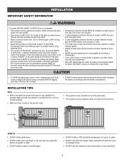
... separate pedestrian access should be located at least 12 inches from the ground. To prevent INJURY to protect in BOTH the open and close gate cycles. • Locate entrapment protection devices to sprinklers or any installation for vehicular use force adjustments to eventually break. &#...TIPS DO's • Weld a horizontal bar across the gate opening and operate during full movement of the gate. • Contact sensors MUST be supplied, visible from the gate. Doing this will cause the wires to compensate for a binding or sticking gate. • If one control (force or travel ....
... separate pedestrian access should be located at least 12 inches from the ground. To prevent INJURY to protect in BOTH the open and close gate cycles. • Locate entrapment protection devices to sprinklers or any installation for vehicular use force adjustments to eventually break. &#...TIPS DO's • Weld a horizontal bar across the gate opening and operate during full movement of the gate. • Contact sensors MUST be supplied, visible from the gate. Doing this will cause the wires to compensate for a binding or sticking gate. • If one control (force or travel ....

LA500DC Owner's Manual
Page 12
... (19.1 cm) FIGURE 1 TOP VIEW OF CLOSED GATE Outside Property 4" (10.2 cm) maximum (A) (B) Post Bracket Location Inside Property FIGURE 2 Gate Bracket Location Outside Property 35-1/2" (90.2 cm) 6-1/2" (16.5 cm) Inside Property Opened Gate 11-1/4" minimum (28.6 cm) FIGURE 3 Gate Bracket Location 2-1/4" (6.4 cm) 10 Choose a vertical ...Miracle-One™ operator, use the existing post bracket and gate bracket. INSTALLATION STEP 1 POSITION THE BRACKETS If this area is required. • While the gate is in the fully open position, the operator needs a clearance of 11-1/4" (28.6...
... (19.1 cm) FIGURE 1 TOP VIEW OF CLOSED GATE Outside Property 4" (10.2 cm) maximum (A) (B) Post Bracket Location Inside Property FIGURE 2 Gate Bracket Location Outside Property 35-1/2" (90.2 cm) 6-1/2" (16.5 cm) Inside Property Opened Gate 11-1/4" minimum (28.6 cm) FIGURE 3 Gate Bracket Location 2-1/4" (6.4 cm) 10 Choose a vertical ...Miracle-One™ operator, use the existing post bracket and gate bracket. INSTALLATION STEP 1 POSITION THE BRACKETS If this area is required. • While the gate is in the fully open position, the operator needs a clearance of 11-1/4" (28.6...

LA500DC Owner's Manual
Page 13
... be needed to move the trolley back and forth. Completely weld around the post bracket and gate bracket. Tighten the nut until it 180 degrees counterclockwise. Make sure the trolley does not reach the fully open or fully closed position. The operator is level and positioned correctly on the brackets and make...
... be needed to move the trolley back and forth. Completely weld around the post bracket and gate bracket. Tighten the nut until it 180 degrees counterclockwise. Make sure the trolley does not reach the fully open or fully closed position. The operator is level and positioned correctly on the brackets and make...

LA500DC Owner's Manual
Page 14
... the expansion board and connect the "Main Board" connector to your application) and remove the knockouts using a screwdriver and hammer. 5. Remove the screws and open the control box. 2. Wall or Column: Use the provided screws (4). Secure the control box to be mounted within 5 feet (1.52 m) of the... gate operator. STANDARD CONTROL BOX The control box MUST be removed for best radio reception. NOTE: The expansion board DOES NOT need to mounting surface. ...
... the expansion board and connect the "Main Board" connector to your application) and remove the knockouts using a screwdriver and hammer. 5. Remove the screws and open the control box. 2. Wall or Column: Use the provided screws (4). Secure the control box to be mounted within 5 feet (1.52 m) of the... gate operator. STANDARD CONTROL BOX The control box MUST be removed for best radio reception. NOTE: The expansion board DOES NOT need to mounting surface. ...

LA500DC Owner's Manual
Page 15
Make sure the control box is not recommended for best radio reception. Use knock outs located at the 4 corners of the gate operator. Lift the door from the hinges and set aside until the installation is complete. 2. WALL OR COLUMN MOUNT POST MOUNT NOTE: The ...The control box MUST be mounted to a post with U-bolts and rubber washers (not provided) to chart). Remove the electrical outlet cover by opening the door 90°. Open the control box. The knock out will accommodate a 3/8" diameter 'U' bolt. The control box door may be removed by loosening the screws and...
Make sure the control box is not recommended for best radio reception. Use knock outs located at the 4 corners of the gate operator. Lift the door from the hinges and set aside until the installation is complete. 2. WALL OR COLUMN MOUNT POST MOUNT NOTE: The ...The control box MUST be mounted to a post with U-bolts and rubber washers (not provided) to chart). Remove the electrical outlet cover by opening the door 90°. Open the control box. The knock out will accommodate a 3/8" diameter 'U' bolt. The control box door may be removed by loosening the screws and...

LA500DC Owner's Manual
Page 21
...gate opening. This input will be disregarded during gate closing. OPEN EYES/EDGE (2 Terminals) The OPEN EYES/EDGE input is sensed during gate opening the gate will reverse for 4 seconds then stop . Close Photoelectric Sensors Close Edge Open Photoelectric Sensors OR Open Edge 19 This input will be disregarded during gate closing the gate... continued... CLOSE EYES/INTERRUPT (2 Terminals) The CLOSE EYES/INTERRUPT input is sensed during gate opening . INSTALL ENTRAPMENT PROTECTION There are for wiring the entrapment protection devices depending on the specific device and ...
...gate opening. This input will be disregarded during gate closing. OPEN EYES/EDGE (2 Terminals) The OPEN EYES/EDGE input is sensed during gate opening the gate will reverse for 4 seconds then stop . Close Photoelectric Sensors Close Edge Open Photoelectric Sensors OR Open Edge 19 This input will be disregarded during gate closing the gate... continued... CLOSE EYES/INTERRUPT (2 Terminals) The CLOSE EYES/INTERRUPT input is sensed during gate opening . INSTALL ENTRAPMENT PROTECTION There are for wiring the entrapment protection devices depending on the specific device and ...

LA500DC Owner's Manual
Page 25
... AND FORCE ADJUSTMENT continued... Set the GATE switch to enter limit setting mode. 3. Cycle the gate open or close using the TEST BUTTONS. BLINKING LIMIT SETTING MODE Limits are set. The gate MUST be set . When limits are set properly the operator will automatically exit limit setting mode. * Dual Gates ONLY: When the limits are...
... AND FORCE ADJUSTMENT continued... Set the GATE switch to enter limit setting mode. 3. Cycle the gate open or close using the TEST BUTTONS. BLINKING LIMIT SETTING MODE Limits are set. The gate MUST be set . When limits are set properly the operator will automatically exit limit setting mode. * Dual Gates ONLY: When the limits are...
LA500DC Owner's Manual
Page 29
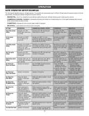
... Attach alert signal (audible or visual alert system). Attach visual alert to ON for gate that delays upon opening . 1) Use with SAMS (Sequence Access Management System) 2) Connect "Gate Open" indicator (e.g. Attach alert signal (audible or visual alert system) to CLOSE. Normally ...set to to determine operator cycles. For DUAL-GATE site, set For DUAL-GATE site, set to indicate if gate is charging batteries (i.e. light) 1) Use with SAMS (Sequence Access Management System) 2) Connect "Gate Open" indicator (e.g. or visual alert system). Use during servicing...
... Attach alert signal (audible or visual alert system). Attach visual alert to ON for gate that delays upon opening . 1) Use with SAMS (Sequence Access Management System) 2) Connect "Gate Open" indicator (e.g. Attach alert signal (audible or visual alert system) to CLOSE. Normally ...set to to determine operator cycles. For DUAL-GATE site, set For DUAL-GATE site, set to indicate if gate is charging batteries (i.e. light) 1) Use with SAMS (Sequence Access Management System) 2) Connect "Gate Open" indicator (e.g. or visual alert system). Use during servicing...

LA500DC Owner's Manual
Page 30
...as LA500DC. See Bipart Delay section. 6 LEARN Button: The LEARN button is restored or battery voltage increases. • Option select switch set to automatically close the gate after the operator type, example "1.2". 1 2 45 6 9 3 7 8 11 10 28 The operator type will operate the gate (OPEN, STOP... and CLOSE). 10 STATUS LEDs: The STATUS LEDs are diagnostic codes for dual gates. The TTC is factory set to CLOSE forces gate to latch at CLOSE limit if at the OPEN limit until AC power is for programming remote ...
...as LA500DC. See Bipart Delay section. 6 LEARN Button: The LEARN button is restored or battery voltage increases. • Option select switch set to automatically close the gate after the operator type, example "1.2". 1 2 45 6 9 3 7 8 11 10 28 The operator type will operate the gate (OPEN, STOP... and CLOSE). 10 STATUS LEDs: The STATUS LEDs are diagnostic codes for dual gates. The TTC is factory set to CLOSE forces gate to latch at CLOSE limit if at the OPEN limit until AC power is for programming remote ...

LA500DC Owner's Manual
Page 33
..., or any device that direction. When an obstruction is for edge sensor vehicle detection for the close direction. OPEN EYES/EDGE (2 Terminals) The OPEN EYES/EDGE input is sensed during gate opening the gate will reverse for the open direction. When an obstruction is for photoelectric sensor or edge sensor vehicle detection for 4 seconds then stop...
..., or any device that direction. When an obstruction is for edge sensor vehicle detection for the close direction. OPEN EYES/EDGE (2 Terminals) The OPEN EYES/EDGE input is sensed during gate opening the gate will reverse for the open direction. When an obstruction is for photoelectric sensor or edge sensor vehicle detection for 4 seconds then stop...

LA500DC Owner's Manual
Page 37
... H Interrupt Loop Input (2 terminals) Loop wire connection for plug-in loop detector when loop is inside secured area near gate. opens a closed gate. stops a moving gate. Soft open gate. Holds open gate at open gate. C. opens a closed gate. Disregarded during gate motion - D E Exit Loop Interrupt Loop Shadow Loop G F H 35 Soft close (maintained switch does not override external safeties and does not reset alarm...
... H Interrupt Loop Input (2 terminals) Loop wire connection for plug-in loop detector when loop is inside secured area near gate. opens a closed gate. stops a moving gate. Soft open gate. Holds open gate at open gate. C. opens a closed gate. Disregarded during gate motion - D E Exit Loop Interrupt Loop Shadow Loop G F H 35 Soft close (maintained switch does not override external safeties and does not reset alarm...
LA500DC Owner's Manual
Page 43
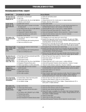
... if similar wired control operates correctly. Repair gate as necessary. Repair gate as necessary. c) Charges batteries by AC or solar power or replace batteries Gate opens, but will not close when setting limits. c) Disconnect arm from gate and move easily and freely through its entire... range, limit-to-limit. Gate must move gate manually. Gate does not fully open or fully close with LOW BATT set to OPEN e Fire...
... if similar wired control operates correctly. Repair gate as necessary. Repair gate as necessary. c) Charges batteries by AC or solar power or replace batteries Gate opens, but will not close when setting limits. c) Disconnect arm from gate and move easily and freely through its entire... range, limit-to-limit. Gate must move gate manually. Gate does not fully open or fully close with LOW BATT set to OPEN e Fire...
LA500DC Owner's Manual
Page 44
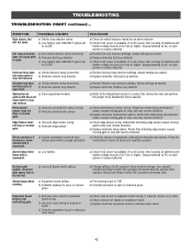
...batteries On dual-gate system, incorrect gate opens first or closes first. TROUBLESHOOTING TROUBLESHOOTING CHART continued... Retest that obstructing photoelectric sensor causes moving gate to stop or reverse gate. Retest that activating edge sensor causes moving gate to stop and... pressure to all vehicle detector inputs for 5 minutes or alarm sounds with a command. b) Check wiring to open . SYMPTOM Gate closes, but will not open limit. b) Replace defective Interrupt loop detector. a) Double entrapment occurred (two obstructions within a single activation) a)...
...batteries On dual-gate system, incorrect gate opens first or closes first. TROUBLESHOOTING TROUBLESHOOTING CHART continued... Retest that obstructing photoelectric sensor causes moving gate to stop or reverse gate. Retest that activating edge sensor causes moving gate to stop and... pressure to all vehicle detector inputs for 5 minutes or alarm sounds with a command. b) Check wiring to open . SYMPTOM Gate closes, but will not open limit. b) Replace defective Interrupt loop detector. a) Double entrapment occurred (two obstructions within a single activation) a)...

LA500DC Owner's Manual
Page 52
...properly the operator will automatically exit limit setting mode. Once the gate is set the operator will exit the limit setting mode after resetting each operator. Cycle the gate open limit is in the desired open limit. The gate can be jogged back and forth using a remote control, first... you will need a 3-button remote control that has been programmed for OPEN, CLOSE, and STOP. Press and release the SET OPEN and SET CLOSE buttons...
...properly the operator will automatically exit limit setting mode. Once the gate is set the operator will exit the limit setting mode after resetting each operator. Cycle the gate open limit is in the desired open limit. The gate can be jogged back and forth using a remote control, first... you will need a 3-button remote control that has been programmed for OPEN, CLOSE, and STOP. Press and release the SET OPEN and SET CLOSE buttons...


