
Solar Gate Access System Daily Cycle Chart Manual
Page 1
... clear LAipnon4wo1ve2ar twiSvheoePnloanwereeGrdMeadatnmeaogAsetcmfocerneot spSeysrsatSteinmygstaotegdaemtleivewDrhaileily Cycle Chart of obstructions and shading for the entire day. The LA500 is not supported in ThPeoLwAe4r1i2s SporolavridGeadtetoActcheessgaStyestoepmeruatitloizrevsiathebainttneorvieasti.ve EvercClhimaragtee®sPwohweerreMteamnapgeermateunrteSsyrsetaecmhtobedleoliwve-r4p°oFw. lL(so)...be cleaned regularly to ensure proper operation. Snow, heavy fog or hrtmrheeemotpoeacaodorocvwahemwmWyyilnmberiBirtnarereeeeIiilGrmnqoanlemwnudBaiszediTofrs...
... clear LAipnon4wo1ve2ar twiSvheoePnloanwereeGrdMeadatnmeaogAsetcmfocerneot spSeysrsatSteinmygstaotegdaemtleivewDrhaileily Cycle Chart of obstructions and shading for the entire day. The LA500 is not supported in ThPeoLwAe4r1i2s SporolavridGeadtetoActcheessgaStyestoepmeruatitloizrevsiathebainttneorvieasti.ve EvercClhimaragtee®sPwohweerreMteamnapgeermateunrteSsyrsetaecmhtobedleoliwve-r4p°oFw. lL(so)...be cleaned regularly to ensure proper operation. Snow, heavy fog or hrtmrheeemotpoeacaodorocvwahemwmWyyilnmberiBirtnarereeeeIiilGrmnqoanlemwnudBaiszediTofrs...
"Manufacturer's Certification for Credit" Manual
Page 1
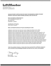
... Operator System (Single Gate Model CSL24V) LiftMaster CSL24V Commercial DC Slide Gate Operator System (Duel Gate Model CSL24V) LiftMaster CSW24V Commercial DC Swing Gate Operator System (Single Gate Model CSW24V) LiftMaster CSW24V Commercial DC Swing Gate Operator System (Duel Gate Model CSW24V) LiftMaster LA500 DC Swing Gate Operator System (Single Gate Model LA500-1PKG) LiftMaster LA500 DC Swing Gate Operator System (Duel Gate Model LA500...
... Operator System (Single Gate Model CSL24V) LiftMaster CSL24V Commercial DC Slide Gate Operator System (Duel Gate Model CSL24V) LiftMaster CSW24V Commercial DC Swing Gate Operator System (Single Gate Model CSW24V) LiftMaster CSW24V Commercial DC Swing Gate Operator System (Duel Gate Model CSW24V) LiftMaster LA500 DC Swing Gate Operator System (Single Gate Model LA500-1PKG) LiftMaster LA500 DC Swing Gate Operator System (Duel Gate Model LA500...
LA500 Manual
Page 1
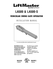
This model is for use on vehicular passage gates ONLY and not intended for use on pedestrian passage gates. UL325 compliant UL991 compliant Visit www.liftmaster.com to locate a professional installing dealer in this manual. This model is intended for use in Class I, II, III and IV vehicular swing gate applications. LA500 & LA500-S VEHICULAR SWING GATE OPERATOR INSTALLATION MANUAL Your model may look different than the model illustrated in your area. THIS PRODUCT IS TO BE INSTALLED AND SERVICED BY A TRAINED GATE SYSTEMS TECHNICIAN ONLY.
This model is for use on vehicular passage gates ONLY and not intended for use on pedestrian passage gates. UL325 compliant UL991 compliant Visit www.liftmaster.com to locate a professional installing dealer in this manual. This model is intended for use in Class I, II, III and IV vehicular swing gate applications. LA500 & LA500-S VEHICULAR SWING GATE OPERATOR INSTALLATION MANUAL Your model may look different than the model illustrated in your area. THIS PRODUCT IS TO BE INSTALLED AND SERVICED BY A TRAINED GATE SYSTEMS TECHNICIAN ONLY.
LA500 Manual
Page 3
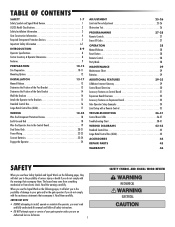
...-28 Remote Controls 27 Erase All Codes 27 OPERATION 28 Manual Release 28 Reset Button 28 Remote Control 28 Party Mode 28 MAINTENANCE 29 Maintenance Chart 29 Batteries 29 ADDITIONAL FEATURES 29-35 LiftMaster Internet Gateway 29 Control Board Overview 30 Accessory ...Features on Control Board 31 Expansion Board Overview 32 Accessory Features on Expansion Board 33 Gate Operator Setup Examples 34 Limit Setup with a Remote Control...
...-28 Remote Controls 27 Erase All Codes 27 OPERATION 28 Manual Release 28 Reset Button 28 Remote Control 28 Party Mode 28 MAINTENANCE 29 Maintenance Chart 29 Batteries 29 ADDITIONAL FEATURES 29-35 LiftMaster Internet Gateway 29 Control Board Overview 30 Accessory ...Features on Control Board 31 Expansion Board Overview 32 Accessory Features on Expansion Board 33 Gate Operator Setup Examples 34 Limit Setup with a Remote Control...
LA500 Manual
Page 4
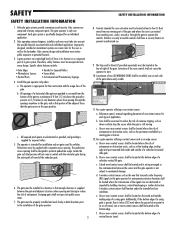
... not servicing the general public, in a home of one independent secondary means of gate travel. RESIDENTIAL VEHICULAR GATE OPERATOR A vehicular gate operator (or system) intended for the UL325 classes. SAFETY UL325 MODEL CLASSIFICATIONS CLASS I single family dwellings, or a garage... or parking area associated therewith. COMMERCIAL/GENERAL ACCESS VEHICULAR GATE OPERATOR A vehicular gate operator (or system) intended for use in which unauthorized access is installed on a single-family residence (UL325 Class I -...
... not servicing the general public, in a home of one independent secondary means of gate travel. RESIDENTIAL VEHICULAR GATE OPERATOR A vehicular gate operator (or system) intended for the UL325 classes. SAFETY UL325 MODEL CLASSIFICATIONS CLASS I single family dwellings, or a garage... or parking area associated therewith. COMMERCIAL/GENERAL ACCESS VEHICULAR GATE OPERATOR A vehicular gate operator (or system) intended for use in which unauthorized access is installed on a single-family residence (UL325 Class I -...
LA500 Manual
Page 5
...component. The Stop and/or Reset (if provided separately) must take into public access areas. 7. A minimum of the gate operator. 3 SAFETY INSTALLATION INFORMATION 8. Reference owner's manual regarding placement of non-contact sensor for installation only on the inside and outside...Outdoor or easily accessible controls shall have a security feature to mechanical damage. b. d. SAFETY SAFETY INSTALLATION INFORMATION 1. The gate operator is specifically designed for entrapment protection functions shall be located at the bottom edge of the gate where easily visible. 11. ...
...component. The Stop and/or Reset (if provided separately) must take into public access areas. 7. A minimum of the gate operator. 3 SAFETY INSTALLATION INFORMATION 8. Reference owner's manual regarding placement of non-contact sensor for installation only on the inside and outside...Outdoor or easily accessible controls shall have a security feature to mechanical damage. b. d. SAFETY SAFETY INSTALLATION INFORMATION 1. The gate operator is specifically designed for entrapment protection functions shall be located at the bottom edge of the gate where easily visible. 11. ...
LA500 Manual
Page 6
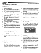
... gate that the gate covers in the horizontal plane parallel to the roadway, between a 1.1 1.2 1.3 Gates shall be permitted on an automatically operated gate. 3.1.5 All gates shall be designed with sufficient lateral stability to prevent a 4 inch (102 mm) diameter sphere from the vertical plane,...edged protrusions not exceeding 0.50 inches (12.7 mm) when other 3. Gates shall have smooth bottom edges, with a powered gate operator. VEHICULAR HORIZONTAL SLIDE GATES fixed object when the gate moves toward the fully open position, subject to the provisions in accordance with ...
... gate that the gate covers in the horizontal plane parallel to the roadway, between a 1.1 1.2 1.3 Gates shall be permitted on an automatically operated gate. 3.1.5 All gates shall be designed with sufficient lateral stability to prevent a 4 inch (102 mm) diameter sphere from the vertical plane,...edged protrusions not exceeding 0.50 inches (12.7 mm) when other 3. Gates shall have smooth bottom edges, with a powered gate operator. VEHICULAR HORIZONTAL SLIDE GATES fixed object when the gate moves toward the fully open position, subject to the provisions in accordance with ...
LA500 Manual
Page 7
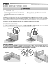
... in that direction will stop and reverse. Safety Non-Contact Sensor Sensor for Close Cycle Sensor for each entrapment zone. This operator contains an inherent (internal) entrapment protection system (the primary entrapment protection system) and REQUIRES the addition of contact where a ...SENSORS) If the electrically activated edge sensor comes in contact with an obstruction while the gate is blocked, then ALL gate operation in that direction until the obstruction is cleared. Unmonitored photoelectric sensor models AOMRON and RETROAB are obligated to test entrapment protection ...
... in that direction will stop and reverse. Safety Non-Contact Sensor Sensor for Close Cycle Sensor for each entrapment zone. This operator contains an inherent (internal) entrapment protection system (the primary entrapment protection system) and REQUIRES the addition of contact where a ...SENSORS) If the electrically activated edge sensor comes in contact with an obstruction while the gate is blocked, then ALL gate operation in that direction until the obstruction is cleared. Unmonitored photoelectric sensor models AOMRON and RETROAB are obligated to test entrapment protection ...

LA500 Manual
Page 8
...and close cycles. • Entrapment protection devices MUST be installed to protect anyone who may be returned to protect in accordance with proper operation of safety reversal system. • NEVER increase force beyond minimum amount required to move gate. • NEVER use force adjustments to... electrical connections MUST be made , the safety reversal system MUST be tested. We recommend that time the unit may come near the operator MUST NOT be properly grounded and connected in BOTH the open and close gate cycles. • Locate entrapment protection devices to protect ...
...and close cycles. • Entrapment protection devices MUST be installed to protect anyone who may be returned to protect in accordance with proper operation of safety reversal system. • NEVER increase force beyond minimum amount required to move gate. • NEVER use force adjustments to... electrical connections MUST be made , the safety reversal system MUST be tested. We recommend that time the unit may come near the operator MUST NOT be properly grounded and connected in BOTH the open and close gate cycles. • Locate entrapment protection devices to protect ...
LA500 Manual
Page 9
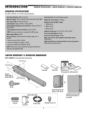
...TROUBLESHOOTING To protect against fire: • Replace ONLY with national and local electrical codes. Pedestrians MUST use ONLY LiftMaster part 29-NP712 for vehicles ONLY. Operator MUST be performed until disconnecting the electrical power (AC or solar and battery) and locking-out the power via ...the operator power switch. Have a qualified service person make repairs to gate hardware. • ALL maintenance MUST be performed by a LiftMaster professional. • Activate gate ONLY when it can increase the risk ...
...TROUBLESHOOTING To protect against fire: • Replace ONLY with national and local electrical codes. Pedestrians MUST use ONLY LiftMaster part 29-NP712 for vehicles ONLY. Operator MUST be performed until disconnecting the electrical power (AC or solar and battery) and locking-out the power via ...the operator power switch. Have a qualified service person make repairs to gate hardware. • ALL maintenance MUST be performed by a LiftMaster professional. • Activate gate ONLY when it can increase the risk ...
LA500 Manual
Page 10
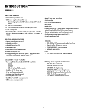
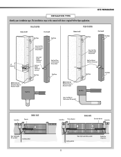
... for toroid transformer (accessory) power: 300 cycles/day semi-continuous duty CARTON INVENTORY & OPERATOR DIMENSIONS NOT SHOWN: Documentation Packet, Hardware Bag 4.21" (10.7 cm) 5.83" (14.8 cm) Operator Model LA500 (1) Model LA500-S (2) 40.35" (102.5 cm) Post Bracket Gate Bracket Warning Signs (2) and... Warranty Card OR Key (2) Terminal Block Connector MODEL LA500-S ONLY Standard Control Box with Toroid Kit ONLY) Solar Power Max:...
... for toroid transformer (accessory) power: 300 cycles/day semi-continuous duty CARTON INVENTORY & OPERATOR DIMENSIONS NOT SHOWN: Documentation Packet, Hardware Bag 4.21" (10.7 cm) 5.83" (14.8 cm) Operator Model LA500 (1) Model LA500-S (2) 40.35" (102.5 cm) Post Bracket Gate Bracket Warning Signs (2) and... Warranty Card OR Key (2) Terminal Block Connector MODEL LA500-S ONLY Standard Control Box with Toroid Kit ONLY) Solar Power Max:...
LA500 Manual
Page 11
... and control from close limit switch - SHADOW - CLOSE LIMIT: OFF at open limit switch - INTERRUPT - CYCLE QUANTITY: LEDs blink operational cycle count 9 EXIT, SHADOW, or INTERRUPT LOOP: accessory connection EXPANSION BOARD FEATURES • Plug-in Loop Detector Connectors (Model LOOPDETLM... Loop Detector) - PRE-ALERT DELAY: ON 3 seconds before gate motion - INTRODUCTION FEATURES FEATURES OPERATOR FEATURES • Advanced "Centerpiece" Control Board • EMI AC Power Surge Protection and Filter Board - OPEN, CLOSE, or STOP...
... and control from close limit switch - SHADOW - CLOSE LIMIT: OFF at open limit switch - INTERRUPT - CYCLE QUANTITY: LEDs blink operational cycle count 9 EXIT, SHADOW, or INTERRUPT LOOP: accessory connection EXPANSION BOARD FEATURES • Plug-in Loop Detector Connectors (Model LOOPDETLM... Loop Detector) - PRE-ALERT DELAY: ON 3 seconds before gate motion - INTRODUCTION FEATURES FEATURES OPERATOR FEATURES • Advanced "Centerpiece" Control Board • EMI AC Power Surge Protection and Filter Board - OPEN, CLOSE, or STOP...
LA500 Manual
Page 12
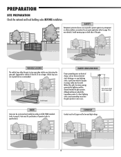
... to ASTM F2200 standards (refer to dissipate its energy safely into the earth. CONDUIT Conduit must be directed towards the gate operator. PREPARATION SITE PREPARATION Check the national and local building codes BEFORE installation. Entrapment Danger Warning Signs VEHICLE LOOPS The vehicle loops...on both sides of a direct lightning strike, proper grounding can protect the gate operator in your gate application (refer to page 5 for proper depth GATE Gate must fit specifications of operator (refer to protect against any entrapment or safety conditions encountered in most cases. SAFETY...
... to ASTM F2200 standards (refer to dissipate its energy safely into the earth. CONDUIT Conduit must be directed towards the gate operator. PREPARATION SITE PREPARATION Check the national and local building codes BEFORE installation. Entrapment Danger Warning Signs VEHICLE LOOPS The vehicle loops...on both sides of a direct lightning strike, proper grounding can protect the gate operator in your gate application (refer to page 5 for proper depth GATE Gate must fit specifications of operator (refer to protect against any entrapment or safety conditions encountered in most cases. SAFETY...
LA500 Manual
Page 13
...this manual will show a typical Pull-to-Open application. Water Tight Conduit (Not provided) Earth Ground Rod Control Box Primary Operator ! DUAL GATE Secondary Operator Junction Box ! Top View Back Steel Plates for Reinforcement (Not provided) Heavy Steel Plate for Reinforcement (Not provided) Back ... if necessary) Gate Hinge Gate Hinge NOTE: Weld Re Bar Behind Gate Hinges for Reinforcement (Not provided) Gate Hinge Control Box Operator SINGLE GATE ! Water Tight Conduit (Not provided) Earth Ground Rod 11 Shielded low voltage wires. PULL-TO-OPEN Column Install Post...
...this manual will show a typical Pull-to-Open application. Water Tight Conduit (Not provided) Earth Ground Rod Control Box Primary Operator ! DUAL GATE Secondary Operator Junction Box ! Top View Back Steel Plates for Reinforcement (Not provided) Heavy Steel Plate for Reinforcement (Not provided) Back ... if necessary) Gate Hinge Gate Hinge NOTE: Weld Re Bar Behind Gate Hinges for Reinforcement (Not provided) Gate Hinge Control Box Operator SINGLE GATE ! Water Tight Conduit (Not provided) Earth Ground Rod 11 Shielded low voltage wires. PULL-TO-OPEN Column Install Post...
LA500 Manual
Page 14
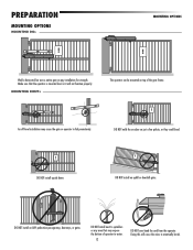
...or downhill gates. PREPARATION MOUNTING OPTIONS MOUNTING DOs ! DO NOT install on just a few pickets, or they could bend. ! MOUNTING OPTIONS ! The operator can be mounted on ANY pedestrian passageways, doorways, or gates. DO NOT install upside down. ! DO NOT install on top of... operator to fail prematurely. Weld a horizontal bar across entire gate on any area that the operator is mounted level or it will cause the wires to sprinklers or any installation for strength. DO ...
...or downhill gates. PREPARATION MOUNTING OPTIONS MOUNTING DOs ! DO NOT install on just a few pickets, or they could bend. ! MOUNTING OPTIONS ! The operator can be mounted on ANY pedestrian passageways, doorways, or gates. DO NOT install upside down. ! DO NOT install on top of... operator to fail prematurely. Weld a horizontal bar across entire gate on any area that the operator is mounted level or it will cause the wires to sprinklers or any installation for strength. DO ...
LA500 Manual
Page 15
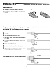
...temporarily mark the location of the first measurement. 5 Measure 8.5 inches from the brackets and proceed to the right. Remove the Miracle-One™ operator from the previous mark. 6 Use a screwdriver to mark the location of the second measurement. 7 Align the post bracket as close as possible above... the screwdriver or dowel rod and tack weld the post bracket in manual mode. If this operator is Push-to-Open, refer to the illustration to page 15. INSTALLATION MANUAL RELEASE + DETERMINE THE POSITION OF THE POST BRACKET MANUAL RELEASE ...
...temporarily mark the location of the first measurement. 5 Measure 8.5 inches from the brackets and proceed to the right. Remove the Miracle-One™ operator from the previous mark. 6 Use a screwdriver to mark the location of the second measurement. 7 Align the post bracket as close as possible above... the screwdriver or dowel rod and tack weld the post bracket in manual mode. If this operator is Push-to-Open, refer to the illustration to page 15. INSTALLATION MANUAL RELEASE + DETERMINE THE POSITION OF THE POST BRACKET MANUAL RELEASE ...
LA500 Manual
Page 16
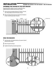
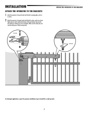
... point and mark the location on the gate. 2 Measure 2.25 inches down from the previous mark and center the bracket on the gate. 2 Remove the operator from the gate. 3 Completely weld around the post bracket and gate bracket. 14 Tack weld the gate bracket in an area that can withstand heavy... forces. Gate Hinge Point 27.75" Gate Bracket Location 2.25" WELD THE BRACKETS 1 Position the operator on the brackets and make sure the operator is level and positioned correctly on this position.
... point and mark the location on the gate. 2 Measure 2.25 inches down from the previous mark and center the bracket on the gate. 2 Remove the operator from the gate. 3 Completely weld around the post bracket and gate bracket. 14 Tack weld the gate bracket in an area that can withstand heavy... forces. Gate Hinge Point 27.75" Gate Bracket Location 2.25" WELD THE BRACKETS 1 Position the operator on the brackets and make sure the operator is level and positioned correctly on this position.
LA500 Manual
Page 17
.... Tighten the nut until it reaches the bottom of the gate bracket, then turn the nut a half turn, making sure not to install the second operator. 15 Make sure the trolley does not reach the fully open or fully closed position. INSTALLATION ATTACH THE...
.... Tighten the nut until it reaches the bottom of the gate bracket, then turn the nut a half turn, making sure not to install the second operator. 15 Make sure the trolley does not reach the fully open or fully closed position. INSTALLATION ATTACH THE...
LA500 Manual
Page 18
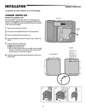
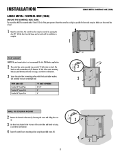
Column: Use the provided screws (4). NOTE: The expansion board DOES NOT need to be mounted within 5 feet (1.52 m) of the gate operator. Post: Use U-bolts and rubber washers (not provided) to mounting surface. STANDARD CONTROL BOX MOUNT THE CONTROL BOX The control box MUST be removed for ...
Column: Use the provided screws (4). NOTE: The expansion board DOES NOT need to be mounted within 5 feet (1.52 m) of the gate operator. Post: Use U-bolts and rubber washers (not provided) to mounting surface. STANDARD CONTROL BOX MOUNT THE CONTROL BOX The control box MUST be removed for ...
LA500 Manual
Page 19
.... 2 The control box can be removed by loosening the screws and sliding the cover up. 3 Use knock outs located at the 4 corners of the gate operator. Make sure the control box is not recommended for best radio reception. The control box door may be mounted to a post with U-bolts and rubber...
.... 2 The control box can be removed by loosening the screws and sliding the cover up. 3 Use knock outs located at the 4 corners of the gate operator. Make sure the control box is not recommended for best radio reception. The control box door may be mounted to a post with U-bolts and rubber...


