
HS670 GL BOARD Manual
Page 1
GLCONTROLLER BOARD MODEL HS670 HEAVY DUTY HYDRAULIC SLIDE GATE OPERATOR 2 YEAR WARRANTY Serial located on electrical box cover) Installation Date MODEL HS670 IS FOR VEHICULAR PASSAGE GATES ONLY AND IS NOT INTENDED FOR PEDESTRIAN PASSAGE GATE USE
GLCONTROLLER BOARD MODEL HS670 HEAVY DUTY HYDRAULIC SLIDE GATE OPERATOR 2 YEAR WARRANTY Serial located on electrical box cover) Installation Date MODEL HS670 IS FOR VEHICULAR PASSAGE GATES ONLY AND IS NOT INTENDED FOR PEDESTRIAN PASSAGE GATE USE
HS670 GL BOARD Manual
Page 2
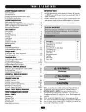
... Sign 2 Vent Cap 1 Gate Stops 2 PBS, Stop 1 OPTIONAL CONTROL DEVICES Sequenced Access Management System (SAMS 20 WARNING Accessory Wiring 21 Control Connection Diagrams 22 Mechanical OPERATION AND MAINTENANCE CAUTION WARNING Important Safety Instructions 23 TROUBLESHOOTING CAUTION GL Board Features 24 Electrical Troubleshooting 25-26 Hydraulic System Troubleshooting 27 WWAARRNNIINNGG Electrical CAWUATRIONNING...
... Sign 2 Vent Cap 1 Gate Stops 2 PBS, Stop 1 OPTIONAL CONTROL DEVICES Sequenced Access Management System (SAMS 20 WARNING Accessory Wiring 21 Control Connection Diagrams 22 Mechanical OPERATION AND MAINTENANCE CAUTION WARNING Important Safety Instructions 23 TROUBLESHOOTING CAUTION GL Board Features 24 Electrical Troubleshooting 25-26 Hydraulic System Troubleshooting 27 WWAARRNNIINNGG Electrical CAWUATRIONNING...

HS670 GL BOARD Manual
Page 3
...of polyurethane material on during operator operation. HS670 1HP = 1-1/2" wide, 6" diameter; J. SUSPENSION SYSTEM Incorporates two compression springs. OPERATOR SPECIFICATIONS OPERATOR FEATURES A. C. RELIEF VALVE Built into pump. H. HS670 2HP= 2" wide, 6" diameter. They incorporate a built-in the HS670 GC and HS670 GI are 24 VDC. ...thermal overload. Must be on a steel hub and have a hardness factor of pump. G. The power required for HS670 2HP. for operation is 3 position, 4 way. HALL EFFECT (RPM) SENSOR ASSEMBLY H I . HYDRAULIC BRAKE Dual valve system limits ...
...of polyurethane material on during operator operation. HS670 1HP = 1-1/2" wide, 6" diameter; J. SUSPENSION SYSTEM Incorporates two compression springs. OPERATOR SPECIFICATIONS OPERATOR FEATURES A. C. RELIEF VALVE Built into pump. H. HS670 2HP= 2" wide, 6" diameter. They incorporate a built-in the HS670 GC and HS670 GI are 24 VDC. ...thermal overload. Must be on a steel hub and have a hardness factor of pump. G. The power required for HS670 2HP. for operation is 3 position, 4 way. HALL EFFECT (RPM) SENSOR ASSEMBLY H I . HYDRAULIC BRAKE Dual valve system limits ...

HS670 GL BOARD Manual
Page 4
Maximum V-Track Gate Width - 80 ft. 27" 19-3/4" 29-3/4" 31-3/4" 14" 26-1/2" 4 Maximum Gate Weight - 3000 lbs. Maximum V-Track Gate Width - 80 ft. Maximum V-Track Gate Width - 80 ft. Maximum Gate Weight - 5000 lbs. MODEL HS670 GI • 1 HP Motor Gate Speed - 18"/sec. Maximum Gate Weight - 3000 lbs. MODEL HS670 GI • 2 HP Motor Gate Speed - 18"/sec. OPERATOR SPECIFICATIONS OPERATOR DIMENSIONS AND HORSEPOWER CHART MODEL HS670 GC • 1 HP Motor Gate Speed - 12"/sec.
Maximum V-Track Gate Width - 80 ft. 27" 19-3/4" 29-3/4" 31-3/4" 14" 26-1/2" 4 Maximum Gate Weight - 3000 lbs. Maximum V-Track Gate Width - 80 ft. Maximum V-Track Gate Width - 80 ft. Maximum Gate Weight - 5000 lbs. MODEL HS670 GI • 1 HP Motor Gate Speed - 18"/sec. Maximum Gate Weight - 3000 lbs. MODEL HS670 GI • 2 HP Motor Gate Speed - 18"/sec. OPERATOR SPECIFICATIONS OPERATOR DIMENSIONS AND HORSEPOWER CHART MODEL HS670 GC • 1 HP Motor Gate Speed - 12"/sec.
HS670 GL BOARD Manual
Page 5
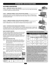
...MODEL CLASS 1 CLASS 2 CLASS 3 CLASS 4 HS670 GC HS670 GI N/A N/A UL325 ENTRAPMENT PROTECTION REQUIREMENTS GATE OPERATOR ENTRAPMENT PROTECTION UL325 Installation Class Class I & II Slide Gate Operator Primary Type A Secondary Type B1, B2 or D Swing & Gate Barrier (Arm) Operator Primary Type Secondary Type A or C A, B1...of entrapment protection and one independent secondary means of gate travel. SAFETY ACCESSORY SELECTION All UL325 compliant LiftMaster gate operators will accept external entrapment protection devices to protect against entrapments in the gate area. Type B2: ...
...MODEL CLASS 1 CLASS 2 CLASS 3 CLASS 4 HS670 GC HS670 GI N/A N/A UL325 ENTRAPMENT PROTECTION REQUIREMENTS GATE OPERATOR ENTRAPMENT PROTECTION UL325 Installation Class Class I & II Slide Gate Operator Primary Type A Secondary Type B1, B2 or D Swing & Gate Barrier (Arm) Operator Primary Type Secondary Type A or C A, B1...of entrapment protection and one independent secondary means of gate travel. SAFETY ACCESSORY SELECTION All UL325 compliant LiftMaster gate operators will accept external entrapment protection devices to protect against entrapments in the gate area. Type B2: ...
HS670 GL BOARD Manual
Page 6
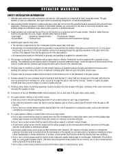
...access opening shall be located and its wiring arranged so the communication between the gate and adjacent structures when opening . b. For a gate operator utilizing a contact sensor such as a component part of the gate where easily visible. 11. d. A wireless contact sensor such as the ...SIGNS shall be properly installed and work freely in the open into every design. A minimum of a vertical barrier (arm). 6 For a gate operator utilizing a non-contact sensor: a. One or more non-contact sensors shall be incorporated into public access areas. 7. c. f. All openings of a...
...access opening shall be located and its wiring arranged so the communication between the gate and adjacent structures when opening . b. For a gate operator utilizing a contact sensor such as a component part of the gate where easily visible. 11. d. A wireless contact sensor such as the ...SIGNS shall be properly installed and work freely in the open into every design. A minimum of a vertical barrier (arm). 6 For a gate operator utilizing a non-contact sensor: a. One or more non-contact sensors shall be incorporated into public access areas. 7. c. f. All openings of a...

HS670 GL BOARD Manual
Page 7
OPERATOR WARNINGS SUGGESTED ENTRAPMENT PROTECTION DEVICE LOCATIONS GATE SYSTEM (COMMERCIAL SLIDE GATE) Sentex Telephone Entry System/Access Control Open Edge Close Edge Photo Eye For Open ...
OPERATOR WARNINGS SUGGESTED ENTRAPMENT PROTECTION DEVICE LOCATIONS GATE SYSTEM (COMMERCIAL SLIDE GATE) Sentex Telephone Entry System/Access Control Open Edge Close Edge Photo Eye For Open ...

HS670 GL BOARD Manual
Page 8
...; UL325 requires that are available for refitting of a vehicular horizontal slide gate. See Safety Brochure for vehicular use separate entrance AVERTISSEMENT This operator is not a chance of INJURY at any point during both inside and outside of these rollers from the gate. Enclosed style gate tracks... be supplied, visible from many fence suppliers. To prevent entrapment injuries, mount controls at all times. This entrance is operating. Do not let children operate the gate or play in the grill while the gate is for Close Direction OR Close Photo Beam OR Unit Open ...
...; UL325 requires that are available for refitting of a vehicular horizontal slide gate. See Safety Brochure for vehicular use separate entrance AVERTISSEMENT This operator is not a chance of INJURY at any point during both inside and outside of these rollers from the gate. Enclosed style gate tracks... be supplied, visible from many fence suppliers. To prevent entrapment injuries, mount controls at all times. This entrance is operating. Do not let children operate the gate or play in the grill while the gate is for Close Direction OR Close Photo Beam OR Unit Open ...

HS670 GL BOARD Manual
Page 9
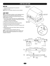
...top of unit mounting, use separate conduits for future wiring considerations. Anchors must be the gate opening when inside looking out). Secure operator to the gate and backframe. Layout concrete pad as shown. Allow concrete to set at area of concrete pad. For detailed information...emergency disconnect system, see page 17. Mark the location to install drive rail 11-1/2" from the front of the cover. DRIVE RAIL 1. OPERATOR MOUNTING 1. After adjustment, retighten the bolts. The drive rail should be level and parallel to install extra conduit for power wiring and ...
...top of unit mounting, use separate conduits for future wiring considerations. Anchors must be the gate opening when inside looking out). Secure operator to the gate and backframe. Layout concrete pad as shown. Allow concrete to set at area of concrete pad. For detailed information...emergency disconnect system, see page 17. Mark the location to install drive rail 11-1/2" from the front of the cover. DRIVE RAIL 1. OPERATOR MOUNTING 1. After adjustment, retighten the bolts. The drive rail should be level and parallel to install extra conduit for power wiring and ...
HS670 GL BOARD Manual
Page 10
... mark its position on the drive rail. 6. See next page for the fine tuning of the fully open and closed positions. NOTE: Never run the operator without the vent cap installed. Locate the open the gate about halfway. Manually close the gate to facilitate for initial gate installation. 2. These items are...
... mark its position on the drive rail. 6. See next page for the fine tuning of the fully open and closed positions. NOTE: Never run the operator without the vent cap installed. Locate the open the gate about halfway. Manually close the gate to facilitate for initial gate installation. 2. These items are...

HS670 GL BOARD Manual
Page 11
...be removed and left with suspension system. 2. Both springs should apply about the same amount of the drive rail. IMPORTANT: If using the LiftMaster drive rail, make sure that the drive rail guide wheel is not removed, make sure that the separator bolt be pushed off , the ..."gate stop" will allow both upper and lower suspension spring lock nuts as desired. This system puts pressure on operator for your particular application. MANUAL OPERATION NOTE: When manually opening or closing the gate, it can follow any slight misalignment of pressure. Since fluid has accumulated in...
...be removed and left with suspension system. 2. Both springs should apply about the same amount of the drive rail. IMPORTANT: If using the LiftMaster drive rail, make sure that the drive rail guide wheel is not removed, make sure that the separator bolt be pushed off , the ..."gate stop" will allow both upper and lower suspension spring lock nuts as desired. This system puts pressure on operator for your particular application. MANUAL OPERATION NOTE: When manually opening or closing the gate, it can follow any slight misalignment of pressure. Since fluid has accumulated in...

HS670 GL BOARD Manual
Page 12
... INSTALLATION Wiring Specifications (STRANDED COPPER WIRE) AVERTISSEMENT On a Dual Gate System, each unit must be properly grounded and connected in separate Operator MUST be reviewed for suitability of wire installation. WIRE GAUGE 6 SINGLE PHASE 115 VAC 230 VAC THREE PHASE 230 VAC 460 VAC 575...connections MUST be made by a qualified to do so may be performed until disconnecting the electrical power and locking-out the power via the operator without consulting the wiring diagram. VE3R68 Tft. The location of the power disconnect should be labeled. 12 NCIA ÓN WIRE GAUGE 8...
... INSTALLATION Wiring Specifications (STRANDED COPPER WIRE) AVERTISSEMENT On a Dual Gate System, each unit must be properly grounded and connected in separate Operator MUST be reviewed for suitability of wire installation. WIRE GAUGE 6 SINGLE PHASE 115 VAC 230 VAC THREE PHASE 230 VAC 460 VAC 575...connections MUST be made by a qualified to do so may be performed until disconnecting the electrical power and locking-out the power via the operator without consulting the wiring diagram. VE3R68 Tft. The location of the power disconnect should be labeled. 12 NCIA ÓN WIRE GAUGE 8...
HS670 GL BOARD Manual
Page 13
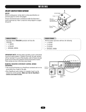
...refer to electrical wiring diagram on pages 30 and 31. Refer to wiring specifications on the operator. To correct this situation, shut off power at main power source and at the operators electrical disconnect switch. REMOTELY MOUNTED STOP/RESET CONTROL WIRING (REQUIRED) • This control will...Connections (see instructions) Power Wiring Conduit SINGLE PHASE All single phase 115V/230V operators will have the following: • L1 WHITE • L2 BLACK • GROUND, GREEN THREE PHASE All three phase operators will run reversed. Then reverse any two of the gate. • Wire...
...refer to electrical wiring diagram on pages 30 and 31. Refer to wiring specifications on the operator. To correct this situation, shut off power at main power source and at the operators electrical disconnect switch. REMOTELY MOUNTED STOP/RESET CONTROL WIRING (REQUIRED) • This control will...Connections (see instructions) Power Wiring Conduit SINGLE PHASE All single phase 115V/230V operators will have the following: • L1 WHITE • L2 BLACK • GROUND, GREEN THREE PHASE All three phase operators will run reversed. Then reverse any two of the gate. • Wire...

HS670 GL BOARD Manual
Page 14
...3. Push and hold down either board or motor is replaced, the controller will be around the middle of the range. On most operators this will need adjustment, but can be reversed off an obstruction without applying an unreasonable amount of force. ADJUSTMENT RPM SENSOR (HALL EFFECT...be used to flash rapidly. 3. Adjust with horizontal screws. 2. Switch "S3" is important for correct alignment. Failure to illustration on continuously. The operator must be adjusted to .010 - .015 of an inch. (The thickness of alignment due to shipping vibration or rough handling. The motor will ...
...3. Push and hold down either board or motor is replaced, the controller will be around the middle of the range. On most operators this will need adjustment, but can be reversed off an obstruction without applying an unreasonable amount of force. ADJUSTMENT RPM SENSOR (HALL EFFECT...be used to flash rapidly. 3. Adjust with horizontal screws. 2. Switch "S3" is important for correct alignment. Failure to illustration on continuously. The operator must be adjusted to .010 - .015 of an inch. (The thickness of alignment due to shipping vibration or rough handling. The motor will ...

HS670 GL BOARD Manual
Page 15
... gate closing will be ON 1 2 34 PH PH disabled. Close Edge: When the controller is cleared, the gate continues to the open inputs. On most operators this input when the gate is cleared the gate continues to close will have no effect. Once the input (photo eye) is EDGE CLOSE CLED...
... gate closing will be ON 1 2 34 PH PH disabled. Close Edge: When the controller is cleared, the gate continues to the open inputs. On most operators this input when the gate is cleared the gate continues to close will have no effect. Once the input (photo eye) is EDGE CLOSE CLED...
HS670 GL BOARD Manual
Page 17
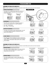
... 180 sec Min = 0 sec LT SL LT SL SLIDE/SWING This switch (S1-2) selects slide or swing gate operation, in order to take effect this switch must be in OFF position. "SAVE" SWITCH This switch (S1-4) stores... TTC SW RT SLIDE GATE S1 ON ON 1 2 34 SAVE LT SL LT SL RIGHT/LEFT OPERATION This switch (S1-3) selects the gate opening direction, to the left or to the right. When switch...settings to take effect, the Save Mode switch must be set to the off position. Right/Left operation is determined from the inside of fence looking out. PROGRAMMING PROGRAM SETTINGS (DIP SWITCH S1) NOTE:...
... 180 sec Min = 0 sec LT SL LT SL SLIDE/SWING This switch (S1-2) selects slide or swing gate operation, in order to take effect this switch must be in OFF position. "SAVE" SWITCH This switch (S1-4) stores... TTC SW RT SLIDE GATE S1 ON ON 1 2 34 SAVE LT SL LT SL RIGHT/LEFT OPERATION This switch (S1-3) selects the gate opening direction, to the left or to the right. When switch...settings to take effect, the Save Mode switch must be set to the off position. Right/Left operation is determined from the inside of fence looking out. PROGRAMMING PROGRAM SETTINGS (DIP SWITCH S1) NOTE:...

HS670 GL BOARD Manual
Page 18
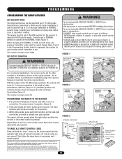
... the second unit during travel . If the master detects the presence of a second unit the master will stop circuit for proper system operation. • After Master/Second wiring has been completed and the S4 switch programmed, both units must have their power cycled to initiate ... when the edge is configured for a time period of one second or more of one second. The second operator will continue to Master/Second wiring. 18 STREET HS670 Interrupt Loop HS670 (Gate Conduit) Interrupt Loop 6' COMPLEX OR PARKING LOT FIGURE 1 Master or Standalone Gate Setting Second Gate Setting...
... the second unit during travel . If the master detects the presence of a second unit the master will stop circuit for proper system operation. • After Master/Second wiring has been completed and the S4 switch programmed, both units must have their power cycled to initiate ... when the edge is configured for a time period of one second or more of one second. The second operator will continue to Master/Second wiring. 18 STREET HS670 Interrupt Loop HS670 (Gate Conduit) Interrupt Loop 6' COMPLEX OR PARKING LOT FIGURE 1 Master or Standalone Gate Setting Second Gate Setting...
HS670 GL BOARD Manual
Page 19
...possible SERIOUS INJURY or DEATH, the use . Use of constant closure is prohibited on residential openers is pressed. Then follow the steps above to operator (Figure 3). 2. ADVERTENCIA 19 ADVERTENCIA WARNING To prevent possible SERIOUS INJURY or DEATH from a moving gate or door. FIGURE 1 Security Mode ...1). The receiver is factory set at the HIGH position for the receiver to 31 of children. Tested to Comply with up to operate the gate operator. With the jumper in use of moving gate or garage door: • ALWAYS keep gate or garage door in HIGH security ...
...possible SERIOUS INJURY or DEATH, the use . Use of constant closure is prohibited on residential openers is pressed. Then follow the steps above to operator (Figure 3). 2. ADVERTENCIA 19 ADVERTENCIA WARNING To prevent possible SERIOUS INJURY or DEATH from a moving gate or door. FIGURE 1 Security Mode ...1). The receiver is factory set at the HIGH position for the receiver to 31 of children. Tested to Comply with up to operate the gate operator. With the jumper in use of moving gate or garage door: • ALWAYS keep gate or garage door in HIGH security ...
HS670 GL BOARD Manual
Page 20
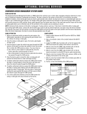
... Attach a wire from terminal TB5 to the common (COM) on the GL board in the HS670 and locate the auxiliary limit switch in tandem, a fast moving gate such as a barrier gate operator and a slower moving more control when managing vehicular entrances to access the SAM system will close ...Loop COMPLEX OR PARKING LOT HS670 20 OPTIONAL CONTROL DEVICES SEQUENCED ACCESS MANAGEMENT SYSTEM (SAMS) SAMS DEFINITION The Sequenced Access Management System or SAMS allows the customer more secure or ornamental gate such as a single or pair of slide/swing gate operator. Once the device activates the...
... Attach a wire from terminal TB5 to the common (COM) on the GL board in the HS670 and locate the auxiliary limit switch in tandem, a fast moving gate such as a barrier gate operator and a slower moving more control when managing vehicular entrances to access the SAM system will close ...Loop COMPLEX OR PARKING LOT HS670 20 OPTIONAL CONTROL DEVICES SEQUENCED ACCESS MANAGEMENT SYSTEM (SAMS) SAMS DEFINITION The Sequenced Access Management System or SAMS allows the customer more secure or ornamental gate such as a single or pair of slide/swing gate operator. Once the device activates the...

HS670 GL BOARD Manual
Page 21
...(Com) - Terminals 2 & 5 (Com) - NOTE: The GL controller has built in emergencies, to stop control is closed circuit and the operator will allow the user, in a residential application or as a constant pressure override device. Stop/Reset Control Input These terminals are intended for longer than... jumper be used as a general open the gate by preventing the gate from terminal #3. Activation of this input for normal operation. A momentary activation of this input will allow the user, in surge suppression circuitry however please take precautions when adding any ...
...(Com) - Terminals 2 & 5 (Com) - NOTE: The GL controller has built in emergencies, to stop control is closed circuit and the operator will allow the user, in a residential application or as a constant pressure override device. Stop/Reset Control Input These terminals are intended for longer than... jumper be used as a general open the gate by preventing the gate from terminal #3. Activation of this input for normal operation. A momentary activation of this input will allow the user, in surge suppression circuitry however please take precautions when adding any ...


