

GT- Logic 4 Installation Manual
Page 2
... Manual Disconnect 17 WIRING 18-19 Power and Ground 18 Control Station 19 ENTRAPMENT PROTECTION 20-22 LiftMaster Monitored Entrapment Protection (LMEP 20 Install the Photoelectric Sensors (Provided 21 Mount the Photoelectric Sensors (Provided 22 Wire the... System Model GT and T 26 Emergency Disconnect System Model APT 26 Emergency Disconnect System Model H, GH, J, and HJ 27 PROGRAMMING 28-35 Introduction to Order Repair Parts 36 TROUBLESHOOTING 37-40 Diagnostic Chart 37 Troubleshooting Guide 38 Troubleshooting Error Codes 39 Troubleshooting Radio Functionality...
... Manual Disconnect 17 WIRING 18-19 Power and Ground 18 Control Station 19 ENTRAPMENT PROTECTION 20-22 LiftMaster Monitored Entrapment Protection (LMEP 20 Install the Photoelectric Sensors (Provided 21 Mount the Photoelectric Sensors (Provided 22 Wire the... System Model GT and T 26 Emergency Disconnect System Model APT 26 Emergency Disconnect System Model H, GH, J, and HJ 27 PROGRAMMING 28-35 Introduction to Order Repair Parts 36 TROUBLESHOOTING 37-40 Diagnostic Chart 37 Troubleshooting Guide 38 Troubleshooting Error Codes 39 Troubleshooting Radio Functionality...
GT- Logic 4 Installation Manual
Page 3
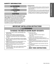
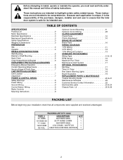
... door operator to power source until instructed to the possibility of door. An improperly balanced door may come from something mechanical or from ALL moving parts of 5 feet (1.5 m). • away from electric shock. Make sure door is visible from the door. 11. When you see this manual and follow all safety...
... door operator to power source until instructed to the possibility of door. An improperly balanced door may come from something mechanical or from ALL moving parts of 5 feet (1.5 m). • away from electric shock. Make sure door is visible from the door. 11. When you see this manual and follow all safety...
GT- Logic 4 Installation Manual
Page 19
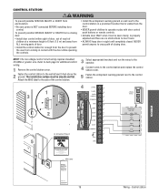
... next to the control station in a prominent location that is visible from coming in Sight at a minimum height of 5 feet (1.5 m) and away from ALL moving parts of the control station. 5 Fasten the entrapment warning placard next to operate or play with the door while operating the controls. Control station The installation...
... next to the control station in a prominent location that is visible from coming in Sight at a minimum height of 5 feet (1.5 m) and away from ALL moving parts of the control station. 5 Fasten the entrapment warning placard next to operate or play with the door while operating the controls. Control station The installation...
GT- Logic 4 Installation Manual
Page 30
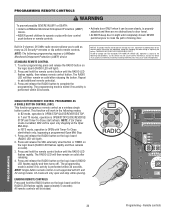
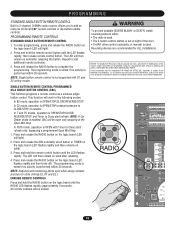
.... C2 mode will then remain on solid after releasing the button. PROGRAMMING REMOTE CONTROLS WARNING To prevent possible SEVERE INJURY or DEATH: CAUTION • Install a LiftMaster Monitored Entrapment Protection (LMEP) • Activate door ONLY when it can be seen clearly, is subject to the following two conditions: (1) this device may not...there are prohibited, except for changing the code setting or replacing the battery. NEVER push buttons or remote controls. THERE ARE NO OTHER USER SERVICEABLE PARTS. This function will be erased. ADVERTENCIA 2. Remote controls
.... C2 mode will then remain on solid after releasing the button. PROGRAMMING REMOTE CONTROLS WARNING To prevent possible SEVERE INJURY or DEATH: CAUTION • Install a LiftMaster Monitored Entrapment Protection (LMEP) • Activate door ONLY when it can be seen clearly, is subject to the following two conditions: (1) this device may not...there are prohibited, except for changing the code setting or replacing the battery. NEVER push buttons or remote controls. THERE ARE NO OTHER USER SERVICEABLE PARTS. This function will be erased. ADVERTENCIA 2. Remote controls

GT- Logic 4 Installation Manual
Page 36
... 5. The brake is available as required. HOW TO ORDER REPAIR PARTS OUR LARGE SERVICE ORGANIZATION SPANS AMERICA Installation and service information are rated for some models. Call our TOLL FREE number: 1-800-528-2806 www.liftmaster.com LIFAEDOVFEORPETREATNOCRIFAEATURE (ODOMETER/CYCLE COUNATEDR)VERTENCIA The operator is observed or suspected... Do not lubricate motor. Check at the factory and should not need additional adjustment for wear and lubricate. Bearings and Shafts LiftMaster Monitored Entrapment Protection (LMEP) Check for the life of the brake assembly.
... 5. The brake is available as required. HOW TO ORDER REPAIR PARTS OUR LARGE SERVICE ORGANIZATION SPANS AMERICA Installation and service information are rated for some models. Call our TOLL FREE number: 1-800-528-2806 www.liftmaster.com LIFAEDOVFEORPETREATNOCRIFAEATURE (ODOMETER/CYCLE COUNATEDR)VERTENCIA The operator is observed or suspected... Do not lubricate motor. Check at the factory and should not need additional adjustment for wear and lubricate. Bearings and Shafts LiftMaster Monitored Entrapment Protection (LMEP) Check for the life of the brake assembly.
GT Logic 4-Repair Parts Manual
Page 1
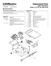
...liftmaster.com Electrical Box Electrical Box Replacement Kits To order a complete electrical box replacement kit, add a K-Prefix to the model number of your operator for example: T5011L4 (Operator) = K-T5011L4 (Electrical Box Kit) Service Kits ITEM PART# K1 K72-10047 K1 K72-10047-1 K2 K72-12515-1 DESCRIPTION Limit Shaft Kit (Models T, APT, SD & GH..., Backup Plate, Depress Plates, Limit Switches, Standoffs, Screws and Locknuts. Replacement Parts Logic 4 Operators Models T, GT, APT, SD, GSD and GH Individual Parts ITEM PART# DESCRIPTION 1 13-10024 2 23-10041 3 K75-35627 4 21-14182 21...
...liftmaster.com Electrical Box Electrical Box Replacement Kits To order a complete electrical box replacement kit, add a K-Prefix to the model number of your operator for example: T5011L4 (Operator) = K-T5011L4 (Electrical Box Kit) Service Kits ITEM PART# K1 K72-10047 K1 K72-10047-1 K2 K72-12515-1 DESCRIPTION Limit Shaft Kit (Models T, APT, SD & GH..., Backup Plate, Depress Plates, Limit Switches, Standoffs, Screws and Locknuts. Replacement Parts Logic 4 Operators Models T, GT, APT, SD, GSD and GH Individual Parts ITEM PART# DESCRIPTION 1 13-10024 2 23-10041 3 K75-35627 4 21-14182 21...
GT Logic 4-Repair Parts Manual
Page 2
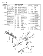
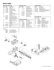
... to 18' #41 Chain (3/4 & 1 HP) Doors to 18' #48 Chain (1/3 & 1/2 HP) Doors to 20' #41 Chain (3/4 & 1 HP) Doors to 20' Individual Parts ITEM PART# DESCRIPTION 1 22-120 Brake Solenoid, 115 Volts 22-35704 Brake Solenoid, 208 Volts 22-240 Brake Solenoid, 230-460 Volts 22-575-1 Brake Solenoid, 575...Cup, Studs, Compression Springs, Brake Solenoid, Solenoid Cover, Spacers, Mounting Plate, Pressure Plate, Feather Key and Conduit. Model T Service Kits ITEM PART# DESCRIPTION K1 71-B120 Brake Kit, 115 Volt Models 71-B208 Brake Kit, 208 Volt Models 71-B240 Brake Kit, 230-460 Volt Models...
... to 18' #41 Chain (3/4 & 1 HP) Doors to 18' #48 Chain (1/3 & 1/2 HP) Doors to 20' #41 Chain (3/4 & 1 HP) Doors to 20' Individual Parts ITEM PART# DESCRIPTION 1 22-120 Brake Solenoid, 115 Volts 22-35704 Brake Solenoid, 208 Volts 22-240 Brake Solenoid, 230-460 Volts 22-575-1 Brake Solenoid, 575...Cup, Studs, Compression Springs, Brake Solenoid, Solenoid Cover, Spacers, Mounting Plate, Pressure Plate, Feather Key and Conduit. Model T Service Kits ITEM PART# DESCRIPTION K1 71-B120 Brake Kit, 115 Volt Models 71-B208 Brake Kit, 208 Volt Models 71-B240 Brake Kit, 230-460 Volt Models...
GT Logic 4-Repair Parts Manual
Page 3
...- Idler Shaft Kit Complete with : Curved Arm, Straight Arm, Door Bracket and Hardware. Door Drive Chain Kits PART# DESCRIPTION 19-5112 19-5114 19-5116 19-5118 19-5120 19-5124 #41 Chain Doors to 8 to 12... #41 Chain Doors to 18' #41 Chain Doors to 20' #41 Chain Doors to 24' Individual Parts ITEM PART# DESCRIPTION 1 22-120 Brake Solenoid, 115 Volts 22-35704 Brake Solenoid, 208 Volts 22-240 Brake Solenoid,...10-10536 Frame 13 10-10205 Header Bracket 14 11-10130 Header Pivot Pin ITEM 15 1/2 HP PART# K20-1050B-2LP K20-3050B-4P K20-3050M-5 3/4 HP K20-1075B-2P K20-3075B-4P K20...
...- Idler Shaft Kit Complete with : Curved Arm, Straight Arm, Door Bracket and Hardware. Door Drive Chain Kits PART# DESCRIPTION 19-5112 19-5114 19-5116 19-5118 19-5120 19-5124 #41 Chain Doors to 8 to 12... #41 Chain Doors to 18' #41 Chain Doors to 20' #41 Chain Doors to 24' Individual Parts ITEM PART# DESCRIPTION 1 22-120 Brake Solenoid, 115 Volts 22-35704 Brake Solenoid, 208 Volts 22-240 Brake Solenoid,...10-10536 Frame 13 10-10205 Header Bracket 14 11-10130 Header Pivot Pin ITEM 15 1/2 HP PART# K20-1050B-2LP K20-3050B-4P K20-3050M-5 3/4 HP K20-1075B-2P K20-3075B-4P K20...
GT Logic 4-Repair Parts Manual
Page 4
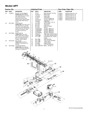
... Washers and Sprockets (41B10x3/4" & 41B16x 3/4"). Intermediate Shaft Kit Complete with : Curved Arm, Straight Arm, Door Bracket and Hardware. Individual Parts Door Drive Chain Kits ITEM PART# DESCRIPTION PART# DESCRIPTION 1 22-120 Brake Solenoid, 115 Volts 19-5810 2 17-6014-1 Motor Pulley 19-5812 3 10-10166 Clutch Plate 19-5814...7" O.D. 5L 9 18-10164 Spring Clutch 10 39-10167 Clutch Disc 11 87-P-075 Push on Fastener. Model APT Service Kits ITEM PART# K1 71-AB120 K2 K72-13057 K3 K72-13059 K4 K75-13074 K5 K72-13058 DESCRIPTION Brake Kit, 115 Volt Models Complete with ...
... Washers and Sprockets (41B10x3/4" & 41B16x 3/4"). Intermediate Shaft Kit Complete with : Curved Arm, Straight Arm, Door Bracket and Hardware. Individual Parts Door Drive Chain Kits ITEM PART# DESCRIPTION PART# DESCRIPTION 1 22-120 Brake Solenoid, 115 Volts 19-5810 2 17-6014-1 Motor Pulley 19-5812 3 10-10166 Clutch Plate 19-5814...7" O.D. 5L 9 18-10164 Spring Clutch 10 39-10167 Clutch Disc 11 87-P-075 Push on Fastener. Model APT Service Kits ITEM PART# K1 71-AB120 K2 K72-13057 K3 K72-13059 K4 K75-13074 K5 K72-13058 DESCRIPTION Brake Kit, 115 Volt Models Complete with ...
GT Logic 4-Repair Parts Manual
Page 5
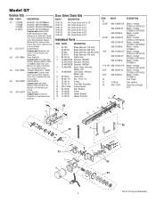
... B12 B1 B4 B15 B14 B16 B7 5 B16 B9 B2 B11 B8 * Call for Bi-Sliding Door Kit Door Disconnect Kit Output Shaft Kit ITEM PART# DESCRIPTION O1 11-10015 Output Shaft O2 12-10331 Flange Bearing O3 15-48B10GXX Sprocket, 48B10x3/4" Bore, Steel O4 15-41B32GXX Sprocket, 41B32x3/4" Bore ... Pressure Plate Assembly B13 80-9001 Feather Key B14 86-CP04-112 Cotter Pin, 1/8"x1-3/4" Zinc Plate B15 87-P-062 Push on Fastener 1 Hardware Kits PART# DESCRIPTION K77-10473 K77-10474 K75-10470 K75-10471 K75-10469 Single Slide Door Kit Bi-Sliding Door Kit Trolley Slider for Single Slide Door...
... B12 B1 B4 B15 B14 B16 B7 5 B16 B9 B2 B11 B8 * Call for Bi-Sliding Door Kit Door Disconnect Kit Output Shaft Kit ITEM PART# DESCRIPTION O1 11-10015 Output Shaft O2 12-10331 Flange Bearing O3 15-48B10GXX Sprocket, 48B10x3/4" Bore, Steel O4 15-41B32GXX Sprocket, 41B32x3/4" Bore ... Pressure Plate Assembly B13 80-9001 Feather Key B14 86-CP04-112 Cotter Pin, 1/8"x1-3/4" Zinc Plate B15 87-P-062 Push on Fastener 1 Hardware Kits PART# DESCRIPTION K77-10473 K77-10474 K75-10470 K75-10471 K75-10469 Single Slide Door Kit Bi-Sliding Door Kit Trolley Slider for Single Slide Door...
GT Logic 4-Repair Parts Manual
Page 6
... Plate Assembly B13 80-9001 Feather Key B14 86-CP04-112 Cotter Pin, 1/8"x1-3/4" Zinc Plate B15 87-P062 Push on Fastener, 5/8" Int. Star ITEM PART# 1 10-10446 2 10-10447 3 K28-10747 4 28-10218 5 28-10219 6 28-10220 7 32-10540 8 DESCRIPTION Mounting Bracket, Electrical Box - X .31 (Available in complete...Kits 71B120 71B208 71B240 71B575 For 115 Volt Operators For 208 Volt Operators For 230-460 Volt Operators For 575 Volt Operators Hardware Kits PART# DESCRIPTION K77-10473 K77-10474 K75-10470 K75-10471 K75-10469 Single Slide Door Kit Bi-Sliding Door Kit Trolley Slider for Single Slide...
... Plate Assembly B13 80-9001 Feather Key B14 86-CP04-112 Cotter Pin, 1/8"x1-3/4" Zinc Plate B15 87-P062 Push on Fastener, 5/8" Int. Star ITEM PART# 1 10-10446 2 10-10447 3 K28-10747 4 28-10218 5 28-10219 6 28-10220 7 32-10540 8 DESCRIPTION Mounting Bracket, Electrical Box - X .31 (Available in complete...Kits 71B120 71B208 71B240 71B575 For 115 Volt Operators For 208 Volt Operators For 230-460 Volt Operators For 575 Volt Operators Hardware Kits PART# DESCRIPTION K77-10473 K77-10474 K75-10470 K75-10471 K75-10469 Single Slide Door Kit Bi-Sliding Door Kit Trolley Slider for Single Slide...
GT Logic 4-Repair Parts Manual
Page 7
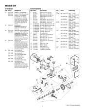
... GH1011L4, GH1021L4 K20-3100C-4P Motor - model GH1053L4 1-1/2 HP K20-1150C-2LP Motor - models GH1023L4, GH1043L4 K20-3100M-5 Motor - Individual Parts ITEM PART# DESCRIPTION 1 22-120 22-35704 22-240 22-575-1 Brake Solenoid, 115 Volts Brake Solenoid, 208 Volts Brake Solenoid, 230-460 Volts Brake...13 18-11008 Compression Spring 14 75-10884 Chain Wheel Assembly 3 15 5 4 ITEM PART# DESCRIPTION 15 1/2 HP K20-1050C-2LP Motor - models GH2023L4, GH2043L4 3 HP K20-3300C-4 Motor - Model GH Service Kits ITEM PART# K1 K75-12584 K75-12585 K75-12586 K2 K75-10177 K3 K72-12789 K75-14661...
... GH1011L4, GH1021L4 K20-3100C-4P Motor - model GH1053L4 1-1/2 HP K20-1150C-2LP Motor - models GH1023L4, GH1043L4 K20-3100M-5 Motor - Individual Parts ITEM PART# DESCRIPTION 1 22-120 22-35704 22-240 22-575-1 Brake Solenoid, 115 Volts Brake Solenoid, 208 Volts Brake Solenoid, 230-460 Volts Brake...13 18-11008 Compression Spring 14 75-10884 Chain Wheel Assembly 3 15 5 4 ITEM PART# DESCRIPTION 15 1/2 HP K20-1050C-2LP Motor - models GH2023L4, GH2043L4 3 HP K20-3300C-4 Motor - Model GH Service Kits ITEM PART# K1 K75-12584 K75-12585 K75-12586 K2 K75-10177 K3 K72-12789 K75-14661...
GH LOGIC VERSION 2 Manual
Page 2
...Control Station Wiring 9 Radio Controls 9 Mounting Instructions 9 Optional Control Mounting 9 Optional Control Wiring 28 CLUTCH ADJUSTMENT Clutch Parts 10 Clutch Adjustment 10 BRAKE ADJUSTMENT Brake Parts 10 WIRING DIAGRAMS 1 PH Wiring 11 3 PH Wiring 12 1 PH Wiring w/Contactor 13 STANDARD PROGRAMMING Wiring Type 14... manual and follow all components were supplied and received undamaged. PACKING LIST K77-14334 PART # 14-10896 19-10929-29 77-11090 19-50106M 02-103L DESCRIPTION GH PARTS BOX 29 FT HAND CHAIN GH PARTS BAG # 50 CHAIN, 106 PITCH 3 BUTTON CONTROL STATION QTY 1 1 1 ...
...Control Station Wiring 9 Radio Controls 9 Mounting Instructions 9 Optional Control Mounting 9 Optional Control Wiring 28 CLUTCH ADJUSTMENT Clutch Parts 10 Clutch Adjustment 10 BRAKE ADJUSTMENT Brake Parts 10 WIRING DIAGRAMS 1 PH Wiring 11 3 PH Wiring 12 1 PH Wiring w/Contactor 13 STANDARD PROGRAMMING Wiring Type 14... manual and follow all components were supplied and received undamaged. PACKING LIST K77-14334 PART # 14-10896 19-10929-29 77-11090 19-50106M 02-103L DESCRIPTION GH PARTS BOX 29 FT HAND CHAIN GH PARTS BAG # 50 CHAIN, 106 PITCH 3 BUTTON CONTROL STATION QTY 1 1 1 ...
GH LOGIC VERSION 2 Manual
Page 20
...Learn button about 5 seconds. 3. The logic board understands this to mean that the software is now set . b) Unlearn the photo eyes from Parts and Service. Turn all the dip switches ON. 2. The Learn LED will turn back on the close button. The Max Run Timer is ...a) Operator control station is wired wrong b) Motor is obstructed or activated. Return the dip switches to factory defaults: 1. Order replacement Chips from Parts and Service. b) Verify voltage getting to Close is now set correctly. The operator will not respond to any commands PROBABLE CAUSE RPM sensor is...
...Learn button about 5 seconds. 3. The logic board understands this to mean that the software is now set . b) Unlearn the photo eyes from Parts and Service. Turn all the dip switches ON. 2. The Learn LED will turn back on the close button. The Max Run Timer is ...a) Operator control station is wired wrong b) Motor is obstructed or activated. Return the dip switches to factory defaults: 1. Order replacement Chips from Parts and Service. b) Verify voltage getting to Close is now set correctly. The operator will not respond to any commands PROBABLE CAUSE RPM sensor is...
GH LOGIC VERSION 2 Manual
Page 22
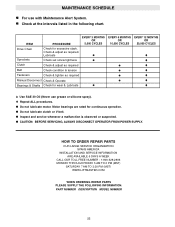
...POWER SUPPLY. Check & adjust as required Manual Disconnect Check & Operate Bearings & Shafts Check for continuous operation. HOW TO ORDER REPAIR PARTS OUR LARGE SERVICE ORGANIZATION SPANS AMERICA INSTALLATION AND SERVICE INFORMATION ARE AVAILABLE 6 DAYS A WEEK CALL OUR TOLL FREE NUMBER - 1-800-... MONDAY THROUGH FRIDAY 5 AM TO 6 PM (MST) SATURDAY 7 AM TO 3:30 PM (MST) WWW.LIFTMASTER.COM WHEN ORDERING REPAIR PARTS PLEASE SUPPLY THE FOLLOWING INFORMATION: PART NUMBER DESCRIPTION MODEL NUMBER 22 ITEM PROCEDURE EVERY 3 MONTHS OR 5,000 CYCLES Drive Chain Sprockets Check for excessive ...
...POWER SUPPLY. Check & adjust as required Manual Disconnect Check & Operate Bearings & Shafts Check for continuous operation. HOW TO ORDER REPAIR PARTS OUR LARGE SERVICE ORGANIZATION SPANS AMERICA INSTALLATION AND SERVICE INFORMATION ARE AVAILABLE 6 DAYS A WEEK CALL OUR TOLL FREE NUMBER - 1-800-... MONDAY THROUGH FRIDAY 5 AM TO 6 PM (MST) SATURDAY 7 AM TO 3:30 PM (MST) WWW.LIFTMASTER.COM WHEN ORDERING REPAIR PARTS PLEASE SUPPLY THE FOLLOWING INFORMATION: PART NUMBER DESCRIPTION MODEL NUMBER 22 ITEM PROCEDURE EVERY 3 MONTHS OR 5,000 CYCLES Drive Chain Sprockets Check for excessive ...
GH LOGIC VERSION 2 Manual
Page 23
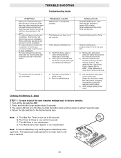
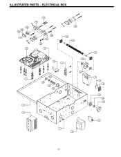
ILLUSTRATED PARTS - ELECTRICAL BOX S6 S5 S2 12 S7 S1 S8 S4 S9 5 S3 L3 L1 10 6 L5 7 L8 L6 L2 L9 L8 2 11 1 3 L7 4 8 9 L2 L6 L4 4 23
ILLUSTRATED PARTS - ELECTRICAL BOX S6 S5 S2 12 S7 S1 S8 S4 S9 5 S3 L3 L1 10 6 L5 7 L8 L6 L2 L9 L8 2 11 1 3 L7 4 8 9 L2 L6 L4 4 23
GH LOGIC VERSION 2 Manual
Page 24
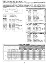
...box, motor or brake components be sure to kit number below . For example: GH5011L = K-GH5011L * Electrical Box Kits include parts K72-12510 and K75-12514 Electrical Box Sub-Assemblies K72-12510 Limit Shaft Assembly K75-12514 Limit Switch Assembly Motor Kits K20-1050C2 ... I .D. Optional modifications and/or accessories included with your operator. ELECTRICAL BOX LOGIC CONTROL (VER. 2.0) Below are replacement kits available for all repair part ordering information. DESCRIPTION 21-14182 21-5460 21-5575 25-2006 25-2008 25-2010 25-2015 25-2020 25-10296 25-11107 25-13840...
...box, motor or brake components be sure to kit number below . For example: GH5011L = K-GH5011L * Electrical Box Kits include parts K72-12510 and K75-12514 Electrical Box Sub-Assemblies K72-12510 Limit Shaft Assembly K75-12514 Limit Switch Assembly Motor Kits K20-1050C2 ... I .D. Optional modifications and/or accessories included with your operator. ELECTRICAL BOX LOGIC CONTROL (VER. 2.0) Below are replacement kits available for all repair part ordering information. DESCRIPTION 21-14182 21-5460 21-5575 25-2006 25-2008 25-2010 25-2015 25-2020 25-10296 25-11107 25-13840...
GH LOGIC VERSION 2 Manual
Page 26
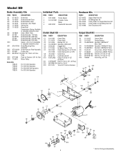
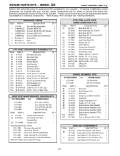
... Release Lever Brake Disk Spring Cup for your operator, certain components may not be added or remove from these lists. MODEL GH LOGIC CONTROL (VER. 2.0) Refer to the parts lists below for replacement kits available for Brake Assembly Brake Stud Spring, Compression x .87" Spacer, .20" x .31...Assembly Kit (230-460V Models) * Brake Kit Voltage same as Operator Voltage. Gear Reducer 1 K75-12783 DISCONNECT ASSEMBLY KIT ITEM PART # DESCRIPTION QTY D1 10-11021 GH Disconnect Lever 1 D2 10-11023 Bevel Gear Yoke 1 D3 10-11024 Brake Release 1 D4 10-11029 Actuator Bracket 1 D5 ...
... Release Lever Brake Disk Spring Cup for your operator, certain components may not be added or remove from these lists. MODEL GH LOGIC CONTROL (VER. 2.0) Refer to the parts lists below for replacement kits available for Brake Assembly Brake Stud Spring, Compression x .87" Spacer, .20" x .31...Assembly Kit (230-460V Models) * Brake Kit Voltage same as Operator Voltage. Gear Reducer 1 K75-12783 DISCONNECT ASSEMBLY KIT ITEM PART # DESCRIPTION QTY D1 10-11021 GH Disconnect Lever 1 D2 10-11023 Bevel Gear Yoke 1 D3 10-11024 Brake Release 1 D4 10-11029 Actuator Bracket 1 D5 ...
GH LOGIC 3 Manual
Page 2
... 24 MAINTENANCE Maintenance Schedule 25 Life of Operator Feature 25 How to Order Repair Parts 25 TROUBLESHOOTING Diagnostic Chart 26 Troubleshooting Guide 27 Troubleshooting Error Codes 28 Troubleshooting Radio Functionality 29 REPAIR PARTS Electrical Box 30-31 Repair Parts Kits 32-33 Operator Notes 34-35 Control Connection Diagram 36 WARNING Mechanical CWWAAUARTRINONIINNNGG...
... 24 MAINTENANCE Maintenance Schedule 25 Life of Operator Feature 25 How to Order Repair Parts 25 TROUBLESHOOTING Diagnostic Chart 26 Troubleshooting Guide 27 Troubleshooting Error Codes 28 Troubleshooting Radio Functionality 29 REPAIR PARTS Electrical Box 30-31 Repair Parts Kits 32-33 Operator Notes 34-35 Control Connection Diagram 36 WARNING Mechanical CWWAAUARTRINONIINNNGG...
GH LOGIC 3 Manual
Page 18
... control(s). 3. NOTE: If Car Dealer mode is enabled, SBC will be open only stopping at the Open Mid-Stop. THERE ARE NO OTHER USER SERVICEABLE PARTS. AVERTISSEMENT ATTENTION P4 E1 R29 C11 D3Ø2 K3 Ø14LGØ6 X1 C54 U1 C71 C78 ® RADIO OLS D25 MID D24 ADVERTENCIA D16...
... control(s). 3. NOTE: If Car Dealer mode is enabled, SBC will be open only stopping at the Open Mid-Stop. THERE ARE NO OTHER USER SERVICEABLE PARTS. AVERTISSEMENT ATTENTION P4 E1 R29 C11 D3Ø2 K3 Ø14LGØ6 X1 C54 U1 C71 C78 ® RADIO OLS D25 MID D24 ADVERTENCIA D16...


