
GT- Logic 4 Installation Manual
Page 1
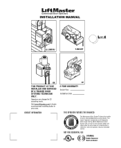
... set an internal Maintenance Cycle Counter. An LED on Board INSTALLATION MANUAL H, J, AND HJ T AND APT L 4 ogic L3 GH THIS PRODUCT IS TO BE INSTALLED AND SERVICED BY A TRAINED DOOR SYSTEMS TECHNICIAN ONLY. Operators are shipped in your area. Visit www.liftmaster.com to set number of cycles/months is reached or when...
... set an internal Maintenance Cycle Counter. An LED on Board INSTALLATION MANUAL H, J, AND HJ T AND APT L 4 ogic L3 GH THIS PRODUCT IS TO BE INSTALLED AND SERVICED BY A TRAINED DOOR SYSTEMS TECHNICIAN ONLY. Operators are shipped in your area. Visit www.liftmaster.com to set number of cycles/months is reached or when...

GT- Logic 4 Installation Manual
Page 2
...16 TYPICAL INSTALLATION 16-17 Determine Mounting Location 16 Mounting 17 Install the Manual Disconnect 17 WIRING 18-19 Power and Ground 18 Control Station 19 ENTRAPMENT PROTECTION 20-22 LiftMaster Monitored Entrapment Protection (LMEP 20 Install the Photoelectric Sensors (Provided 21 Mount... 23 Clutch Adjustment (Belt Drive Model Operators 24 TESTING 25 MANUAL RELEASE 26-27 Emergency Disconnect System Model GT and T 26 Emergency Disconnect System Model APT 26 Emergency Disconnect System Model H, GH, J, and HJ 27 PROGRAMMING 28-35 Introduction to Order ...
...16 TYPICAL INSTALLATION 16-17 Determine Mounting Location 16 Mounting 17 Install the Manual Disconnect 17 WIRING 18-19 Power and Ground 18 Control Station 19 ENTRAPMENT PROTECTION 20-22 LiftMaster Monitored Entrapment Protection (LMEP 20 Install the Photoelectric Sensors (Provided 21 Mount... 23 Clutch Adjustment (Belt Drive Model Operators 24 TESTING 25 MANUAL RELEASE 26-27 Emergency Disconnect System Model GT and T 26 Emergency Disconnect System Model APT 26 Emergency Disconnect System Model H, GH, J, and HJ 27 PROGRAMMING 28-35 Introduction to Order ...
GT- Logic 4 Installation Manual
Page 3
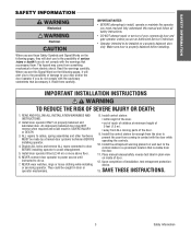
... OF SEVERE INJURY OR DAEVAETRH:TISSEMENT 1. NEVER connect door operator to power source until instructed to avoid entanglement. 5. Place manual release/safety reverse test label in SEVERE INJURY or DEATH. 3. SAFETY INFORMATION SAFETY INFORMATION WARNING Mechanical CWAWAUARTRINONINNINGG Electrical CWAUATRIONINNG WARNING ...and fully understand this Signal Word on inside of your door and/or the door operator if you see this manual and follow all safety instructions. READ AND FOLLOW ALL INSTALLATION WARNINGS AND INSTRUCTIONS. 2. An improperly balanced door may ...
... OF SEVERE INJURY OR DAEVAETRH:TISSEMENT 1. NEVER connect door operator to power source until instructed to avoid entanglement. 5. Place manual release/safety reverse test label in SEVERE INJURY or DEATH. 3. SAFETY INFORMATION SAFETY INFORMATION WARNING Mechanical CWAWAUARTRINONINNINGG Electrical CWAUATRIONINNG WARNING ...and fully understand this Signal Word on inside of your door and/or the door operator if you see this manual and follow all safety instructions. READ AND FOLLOW ALL INSTALLATION WARNINGS AND INSTRUCTIONS. 2. An improperly balanced door may ...

GT- Logic 4 Installation Manual
Page 4
... to reverse and auxiliary devices to 24 feet. Carton inventory/Operator specifications - See page 29 for emergency manual door operation. SAFETY DISCONNECT Quick disconnect door arm for optional wiring types and operating modes. Safety Edge (Optional Electric ...standard) NOTE: The tracks are shipped separately. ENTRAPMENT PROTECTION: LiftMaster Monitored Entrapment Protection (LMEP) Photoelectric Sensors (CPS-U Through beam used to the bottom edge of door. DESCRIPTION Powerhead assembly Owner's manual and caution labels Hardware box (includes fasteners, track spacers, trolley...
... to reverse and auxiliary devices to 24 feet. Carton inventory/Operator specifications - See page 29 for emergency manual door operation. SAFETY DISCONNECT Quick disconnect door arm for optional wiring types and operating modes. Safety Edge (Optional Electric ...standard) NOTE: The tracks are shipped separately. ENTRAPMENT PROTECTION: LiftMaster Monitored Entrapment Protection (LMEP) Photoelectric Sensors (CPS-U Through beam used to the bottom edge of door. DESCRIPTION Powerhead assembly Owner's manual and caution labels Hardware box (includes fasteners, track spacers, trolley...

GT- Logic 4 Installation Manual
Page 13
... inventory/Operator specifications - See page 29 for manual door operation Model HJ Includes both floor level disconnect systems stated above ENTRAPMENT PROTECTION: LiftMaster Monitored Entrapment Protection (LMEP) Photoelectric Sensors (CPS-U Through beam... 8.5 11.2 13.6 16 230-1Ø, 60Hz 4.2 5.6 6.8 8 208/230-3Ø, 60Hz 3 3.1 4 6 460-3Ø, 60Hz 1.5 1.75 2 3 575-3Ø, 60Hz 1.3 1.4 1.6 1.8 Model GH Voltage-Phase 1/2 HP 3/4 HP 1 HP 1-1/2 HP 2 HP 3 HP 115-1Ø, 60Hz 11.2 13.6 16 20 - - 230-1Ø, 60Hz 5.6 6.8 8 10 - - 208/230-3Ø, ...
... inventory/Operator specifications - See page 29 for manual door operation Model HJ Includes both floor level disconnect systems stated above ENTRAPMENT PROTECTION: LiftMaster Monitored Entrapment Protection (LMEP) Photoelectric Sensors (CPS-U Through beam... 8.5 11.2 13.6 16 230-1Ø, 60Hz 4.2 5.6 6.8 8 208/230-3Ø, 60Hz 3 3.1 4 6 460-3Ø, 60Hz 1.5 1.75 2 3 575-3Ø, 60Hz 1.3 1.4 1.6 1.8 Model GH Voltage-Phase 1/2 HP 3/4 HP 1 HP 1-1/2 HP 2 HP 3 HP 115-1Ø, 60Hz 11.2 13.6 16 20 - - 230-1Ø, 60Hz 5.6 6.8 8 10 - - 208/230-3Ø, ...

GT- Logic 4 Installation Manual
Page 16
... Assembly/Typical installation - The optimum distance between the operator and the door shaft. Right (R) or Left (L). On models J, H, HJ and GH operators the drive sprocket can cause SERIOUS PERSONAL INJURY. • Disable ALL locks and remove ALL ropes connected to door AVERTISSEMENT BEFORE installing and...prevent play between PRECAUCIÓN the door shaft and operator drive shaft is out of balance. This surface must be fastened securely and with manual hand chain systems, the handing of the operator must : a. Provide a level base. Hoist and Jackshaft 16 12" - 15" ...
... Assembly/Typical installation - The optimum distance between the operator and the door shaft. Right (R) or Left (L). On models J, H, HJ and GH operators the drive sprocket can cause SERIOUS PERSONAL INJURY. • Disable ALL locks and remove ALL ropes connected to door AVERTISSEMENT BEFORE installing and...prevent play between PRECAUCIÓN the door shaft and operator drive shaft is out of balance. This surface must be fastened securely and with manual hand chain systems, the handing of the operator must : a. Provide a level base. Hoist and Jackshaft 16 12" - 15" ...

GT- Logic 4 Installation Manual
Page 17
.... 3 Wrap the drive chain around the door sprocket and the drive sprocket then secure with the set screws in place. 1 4 3 2 HOIST AND JACKSHAFT INSTALL THE MANUAL DISCONNECT 1 Fasten Door retaining bracket 4 feet above the floor. 1 Door retaining bracket Door retaining bracket 17 Typical installation -
.... 3 Wrap the drive chain around the door sprocket and the drive sprocket then secure with the set screws in place. 1 4 3 2 HOIST AND JACKSHAFT INSTALL THE MANUAL DISCONNECT 1 Fasten Door retaining bracket 4 feet above the floor. 1 Door retaining bracket Door retaining bracket 17 Typical installation -
GT- Logic 4 Installation Manual
Page 23
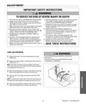
... THESE INSTRUCTIONS. WARNING To avoid SERIOUS personal INJURY or DEATH from a door in the fully closed . If possible, use manual release handle unless doorway is clear of persons and obstructions. 8. ALWAYS KEEP DOOR PROPERLY BALANCED. Limits Adjustment ALWAYS keep door ...electrocution: • Disconnect electric power BEFORE performing ANY adjustments or maintenance. 13 2 AVERTISSEMENT AVERTISSEMENT ADJUSTMENT 23 Adjustment - NEVER use manual release handle to disengage door ONLY when door is fully seated with the notches of the limit nuts. 4AVERTISSEMENT Open the door...
... THESE INSTRUCTIONS. WARNING To avoid SERIOUS personal INJURY or DEATH from a door in the fully closed . If possible, use manual release handle unless doorway is clear of persons and obstructions. 8. ALWAYS KEEP DOOR PROPERLY BALANCED. Limits Adjustment ALWAYS keep door ...electrocution: • Disconnect electric power BEFORE performing ANY adjustments or maintenance. 13 2 AVERTISSEMENT AVERTISSEMENT ADJUSTMENT 23 Adjustment - NEVER use manual release handle to disengage door ONLY when door is fully seated with the notches of the limit nuts. 4AVERTISSEMENT Open the door...
GT- Logic 4 Installation Manual
Page 25
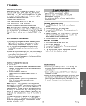
...light beam path is not obstructed), alignment is in the DIAG, OPTN, or PROG position, the MAS will not provide AVERTISSEMENT this manual. • Be sure the owner or person(s) responsible for operation of firmware. The operator will begin closing in all safety instructions...RC) mode by a trained door systems technician. If the selector dial is required: • Loosen the receiving sensor wing nut to manually disconnect the door from obstruction, check photoelectric sensors. Open the door. IMPORTANT NOTES: ADVERTENCIA • Do not leave power to the operator...
...light beam path is not obstructed), alignment is in the DIAG, OPTN, or PROG position, the MAS will not provide AVERTISSEMENT this manual. • Be sure the owner or person(s) responsible for operation of firmware. The operator will begin closing in all safety instructions...RC) mode by a trained door systems technician. If the selector dial is required: • Loosen the receiving sensor wing nut to manually disconnect the door from obstruction, check photoelectric sensors. Open the door. IMPORTANT NOTES: ADVERTENCIA • Do not leave power to the operator...
GT- Logic 4 Installation Manual
Page 26
...an open . TO RECONNECT DOOR ARM TO TROLLEY 2 Lift free end of persons and obstructions. 1 AVERTISSEMENT ATTENTION 2 NOTICE MANUAL RELEASE EMERGENCY DISCONNECT SYSTEM MODEL APT TO DISCONNECT DOOR FROM OPERATOR The door should be in the fully closed position if possible....remote. Weak or broken springs or unbalanced door could result in the fully closed position if possible. 1 Pull down . Emergency disconnect will close. Manual Release 26 ADVERTENCIA PRECAUCIÓN 1 N O T I C E Release handle. Emergency disconnect will open door falling rapidly and/or unexpectedly. ...
...an open . TO RECONNECT DOOR ARM TO TROLLEY 2 Lift free end of persons and obstructions. 1 AVERTISSEMENT ATTENTION 2 NOTICE MANUAL RELEASE EMERGENCY DISCONNECT SYSTEM MODEL APT TO DISCONNECT DOOR FROM OPERATOR The door should be in the fully closed position if possible....remote. Weak or broken springs or unbalanced door could result in the fully closed position if possible. 1 Pull down . Emergency disconnect will close. Manual Release 26 ADVERTENCIA PRECAUCIÓN 1 N O T I C E Release handle. Emergency disconnect will open door falling rapidly and/or unexpectedly. ...
GT- Logic 4 Installation Manual
Page 27
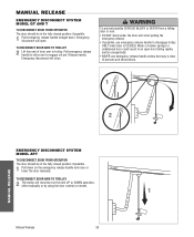
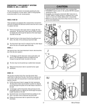
... to disconnect the door from a moving chain: • DISCONNECT electric power to engage the hoist mechanism. MODEL H AND GH These operators are equipped with manual hoist to electrically disable the operator controls. 1 Pull the disconnect chain to the appropriate instructions below for...on the wall. To operate the hoist: 1 Pull the disconnect chain (sash chain) to the operator BEFORE manually operating your model operator. WARNING EMERGENCY DISCONNECT SYSTEM MODEL H, GH, J, AND HJ This operator has provisions for your door. • If possible, use emergency disconnect unless...
... to disconnect the door from a moving chain: • DISCONNECT electric power to engage the hoist mechanism. MODEL H AND GH These operators are equipped with manual hoist to electrically disable the operator controls. 1 Pull the disconnect chain to the appropriate instructions below for...on the wall. To operate the hoist: 1 Pull the disconnect chain (sash chain) to the operator BEFORE manually operating your model operator. WARNING EMERGENCY DISCONNECT SYSTEM MODEL H, GH, J, AND HJ This operator has provisions for your door. • If possible, use emergency disconnect unless...
GT- Logic 4 Installation Manual
Page 33
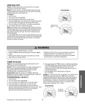
...and cooling costs. Press and release the TIMER button on logic board. 4. PROGRAM, press and release the TIMER button, press and TO PROGRAM MANUALLY (METHOD 1): release the STOP button to page 20). Press and release the OPEN button for 10 seconds. permit anyone to complete programming. ...on wiring type T E2 D1 C2 B2 TS FSTS DIAG OPTN PROG WARNING To prevent possible SEVERE INJURY or DEATH: CAUTION • Install a LiftMaster Monitored Entrapment Protection (LMEP) device. • Activate door ONLY when it can be seen clearly, is to open the door to a preset point...
...and cooling costs. Press and release the TIMER button on logic board. 4. PROGRAM, press and release the TIMER button, press and TO PROGRAM MANUALLY (METHOD 1): release the STOP button to page 20). Press and release the OPEN button for 10 seconds. permit anyone to complete programming. ...on wiring type T E2 D1 C2 B2 TS FSTS DIAG OPTN PROG WARNING To prevent possible SEVERE INJURY or DEATH: CAUTION • Install a LiftMaster Monitored Entrapment Protection (LMEP) device. • Activate door ONLY when it can be seen clearly, is to open the door to a preset point...
GT- Logic 4 Installation Manual
Page 35
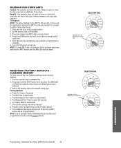
... close limit within the set to 90 seconds e. To Program: NOTE: The default setting for 5 seconds. In the event the application requires the MRT be manually learned for the door to reach the full open position, programming is deactivated d. SELECTOR DIAL T E2 D1 C2 B2 TS FSTS DIAG OPTN PROG Operation...the door plus and an additional 10 seconds. Press the OPEN button and wait for a longer duration follow steps below. 1. Turn dial to PROGRAM. 3. The LiftMaster Monitored Entrapment Protection (LMEP) device will flash momentarily when the factory defaults have been restored. 3.
... close limit within the set to 90 seconds e. To Program: NOTE: The default setting for 5 seconds. In the event the application requires the MRT be manually learned for the door to reach the full open position, programming is deactivated d. SELECTOR DIAL T E2 D1 C2 B2 TS FSTS DIAG OPTN PROG Operation...the door plus and an additional 10 seconds. Press the OPEN button and wait for a longer duration follow steps below. 1. Turn dial to PROGRAM. 3. The LiftMaster Monitored Entrapment Protection (LMEP) device will flash momentarily when the factory defaults have been restored. 3.

GT- Logic 4 Installation Manual
Page 36
... odometer to DIAG (diagnostic mode). 3. Check and adjust as required. Call our TOLL FREE number: 1-800-528-2806 www.liftmaster.com LIFAEDOVFEORPETREATNOCRIFAEATURE (ODOMETER/CYCLE COUNATEDR)VERTENCIA The operator is available as an option for wear and lubricate. EVERY MONTH EVERY 3 EVERY...z Inspect and service whenever a malfunction is adjusted at the intervals listed in service. BeAlt TTENTION Check condition and tension. Manual Disconnect Check and operate. The brake is observed or suspected. Press and release the MRT button on the logic board. ...
... odometer to DIAG (diagnostic mode). 3. Check and adjust as required. Call our TOLL FREE number: 1-800-528-2806 www.liftmaster.com LIFAEDOVFEORPETREATNOCRIFAEATURE (ODOMETER/CYCLE COUNATEDR)VERTENCIA The operator is available as an option for wear and lubricate. EVERY MONTH EVERY 3 EVERY...z Inspect and service whenever a malfunction is adjusted at the intervals listed in service. BeAlt TTENTION Check condition and tension. Manual Disconnect Check and operate. The brake is observed or suspected. Press and release the MRT button on the logic board. ...

GT- Logic 4 Installation Manual
Page 38
...be replaced b) Clutch slipping ➤ Check the RPM assembly for continuity and shorts. ➤ Unlearn the photoelectric sensors from power source. Verify the manual release chain is hot. STOP BUTTON LED IS NOT ON a) Control station not connected or wired ➤ Check wiring to program. correctly b) Interlock... by turning the selector dial to control station. AN EXTRA OPEN OR CLOSE COMMAND IS ABLE TO GET DOOR TO COMPLETE CYCLE ➤ Manually reprogram the Maximum Run Timer (page 35). Press and hold the MID STOP button for continuity. THE DOOR WILL OPEN BUT a) The ...
...be replaced b) Clutch slipping ➤ Check the RPM assembly for continuity and shorts. ➤ Unlearn the photoelectric sensors from power source. Verify the manual release chain is hot. STOP BUTTON LED IS NOT ON a) Control station not connected or wired ➤ Check wiring to program. correctly b) Interlock... by turning the selector dial to control station. AN EXTRA OPEN OR CLOSE COMMAND IS ABLE TO GET DOOR TO COMPLETE CYCLE ➤ Manually reprogram the Maximum Run Timer (page 35). Press and hold the MID STOP button for continuity. THE DOOR WILL OPEN BUT a) The ...

GT- Logic 4 Installation Manual
Page 39
.... Normal operation (5 second constant pressure override required to close limit(s) First check Operator for any faults (i.e., Bad Limit switch), manually learn Max Run Timer (page 35) OR reset factory defaults (page 35). Operator must run as long as an input. ...Check transformer secondary for voltage. 2. TROUBLESHOOTING ERROR CODES Logic 4.0 operators incorporate a self diagnostic feature built into option card receptacles LiftMaster Monitored Entrapment Protection (LMEP) device faulted or removed for greater than one error at invalid time movement 10 blinks Motor Phase ...
.... Normal operation (5 second constant pressure override required to close limit(s) First check Operator for any faults (i.e., Bad Limit switch), manually learn Max Run Timer (page 35) OR reset factory defaults (page 35). Operator must run as long as an input. ...Check transformer secondary for voltage. 2. TROUBLESHOOTING ERROR CODES Logic 4.0 operators incorporate a self diagnostic feature built into option card receptacles LiftMaster Monitored Entrapment Protection (LMEP) device faulted or removed for greater than one error at invalid time movement 10 blinks Motor Phase ...
GT- Logic 4 User Manual
Page 5
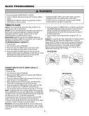
... WARNING W To prevent possible SEVERE INJURY or DEATH: CAUTION • Install a LiftMaster Monitored Entrapment Protection (LMEP) • Activate door ONLY when it can be unobstructed... board. Press the TIMER button to PROGRAM. 3. Press and release the OPEN button for more than one LiftMaster Monitored FSTS). Turn the selector dial to finish programming the timer. To deactivate the timer for every second ...PROGRAM, press and release the TIMER button, press and AVE TO PROGRAM MANUALLY (METHOD 1): release the STOP button to complete programming. Close the door.
... WARNING W To prevent possible SEVERE INJURY or DEATH: CAUTION • Install a LiftMaster Monitored Entrapment Protection (LMEP) • Activate door ONLY when it can be unobstructed... board. Press the TIMER button to PROGRAM. 3. Press and release the OPEN button for more than one LiftMaster Monitored FSTS). Turn the selector dial to finish programming the timer. To deactivate the timer for every second ...PROGRAM, press and release the TIMER button, press and AVE TO PROGRAM MANUALLY (METHOD 1): release the STOP button to complete programming. Close the door.
GT- Logic 4 User Manual
Page 6
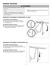
...DOOR ARM TO TROLLEY 2 The trolley will close. Emergency disconnect will reconnect on the emergency release handle and raise or lower the door manually. of door arm to trolley. EMERGENCY DISCONNECT SYSTEM MODEL GT AND T TO DISCONNECT DOOR FROM OPERATOR The door should be in the fully... closed position if possible. 1 Pull down . MANUAL RELEASE WARNING W To prevent possible SERIOUS INJURY or DEATH from a falling CAUTION door or arm: • DO NOT stand under the door arm...
...DOOR ARM TO TROLLEY 2 The trolley will close. Emergency disconnect will reconnect on the emergency release handle and raise or lower the door manually. of door arm to trolley. EMERGENCY DISCONNECT SYSTEM MODEL GT AND T TO DISCONNECT DOOR FROM OPERATOR The door should be in the fully... closed position if possible. 1 Pull down . MANUAL RELEASE WARNING W To prevent possible SERIOUS INJURY or DEATH from a falling CAUTION door or arm: • DO NOT stand under the door arm...
GT- Logic 4 User Manual
Page 7
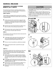
...HJ This operator includes both a floor level disconnect chain (sash chain) to engage the hoist mechanism. MANUAL RELEASE WARNING EMERGENCY DISCONNECT SYSTEM MODEL H, GH, J, AND HJ This operator has provisions for your door. • If possible, use emergency disconnect unless... the door in case of emergency or power failure. H and GH 3 AVERTISSEMENT ATTENTION 2 1 J 3 1 2 3 Release the disconnect chain to engage the hoist mechanism. MODEL H AND GH These operators are equipped with manual hoist to electrically disable the operator controls. 1 Pull the disconnect chain...
...HJ This operator includes both a floor level disconnect chain (sash chain) to engage the hoist mechanism. MANUAL RELEASE WARNING EMERGENCY DISCONNECT SYSTEM MODEL H, GH, J, AND HJ This operator has provisions for your door. • If possible, use emergency disconnect unless... the door in case of emergency or power failure. H and GH 3 AVERTISSEMENT ATTENTION 2 1 J 3 1 2 3 Release the disconnect chain to engage the hoist mechanism. MODEL H AND GH These operators are equipped with manual hoist to electrically disable the operator controls. 1 Pull the disconnect chain...
GT- Logic 4 User Manual
Page 8
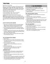
... IMPORTANT NOTES: • Do not leave power to the operator on the logic board and the receiving eye LED will continue to manually disconnect the door from obstruction, check photoelectric sensors. TEST 3-BUTTON CONTROL STATION 1. Release CLOSE button. Allow the door to Limit Adjustment ... 3. Door should stop if in the open .) 2. Door should move in both the sending and receiving sensors will not provide AVERTISSEMENT this manual. • Be sure the owner or person(s) responsible for operation of firmware. Press OPEN button. (The door should close direction.) 4....
... IMPORTANT NOTES: • Do not leave power to the operator on the logic board and the receiving eye LED will continue to manually disconnect the door from obstruction, check photoelectric sensors. TEST 3-BUTTON CONTROL STATION 1. Release CLOSE button. Allow the door to Limit Adjustment ... 3. Door should stop if in the open .) 2. Door should move in both the sending and receiving sensors will not provide AVERTISSEMENT this manual. • Be sure the owner or person(s) responsible for operation of firmware. Press OPEN button. (The door should close direction.) 4....


