EL25-KEYPAD PROGRAMMING Manual
Page 10
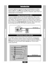
...Page 9 The unit essentially functions as an intercom with this manual. Introduction The sample installations on the next few pages will help familiarize you have questions about your configuration, please contact your installing dealer for more information. When a visitor contacts the resident at... with your residence. Introduction Introduction Bypass Board AUG 10, 2005 WELCOME Telco Phone Line Multi-Resident Complex (Dial-Out) This installation utilizes the dial-out feature. Because the unit dials a separate phone number to contact the resident, the "Call Waiting" and...
...Page 9 The unit essentially functions as an intercom with this manual. Introduction The sample installations on the next few pages will help familiarize you have questions about your configuration, please contact your installing dealer for more information. When a visitor contacts the resident at... with your residence. Introduction Introduction Bypass Board AUG 10, 2005 WELCOME Telco Phone Line Multi-Resident Complex (Dial-Out) This installation utilizes the dial-out feature. Because the unit dials a separate phone number to contact the resident, the "Call Waiting" and...

EL25-KEYPAD PROGRAMMING Manual
Page 25
..."Your" personal layout. Door 4 Activates Relay 4 1 Press Then Important: 1-3 must assign them a "Door Number". If you assign to the installation manual for Wiegand devices to activate one or more relays. Then (#) Internal Keypad is a number you do not know EXACTLY where the External Access Control ...Device(s) are completed by you or your installer, they will Activate Step 4 Assign Each External Access Control 60 Device a "Door Number": To perform these 4 steps you MUST know ...
..."Your" personal layout. Door 4 Activates Relay 4 1 Press Then Important: 1-3 must assign them a "Door Number". If you assign to the installation manual for Wiegand devices to activate one or more relays. Then (#) Internal Keypad is a number you do not know EXACTLY where the External Access Control ...Device(s) are completed by you or your installer, they will Activate Step 4 Assign Each External Access Control 60 Device a "Door Number": To perform these 4 steps you MUST know ...

EL25 - INSTALLATION Manual
Page 1
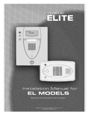
All Rights Reserved ® ® ™ ™ Installation Manual for EL MODELS Telephone entry/access control system © 2008 The Chamberlain Group, Inc.
All Rights Reserved ® ® ™ ™ Installation Manual for EL MODELS Telephone entry/access control system © 2008 The Chamberlain Group, Inc.
EL25 - INSTALLATION Manual
Page 12
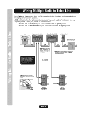
... ID 1 Output Board (See page 6) RES 1 2 Ring Tip TELCO 3 4 Ring Tip Unit ID 2 Output Board (See page 6) Page 10 NOTE: Installation where fiber optic phone lines are present may interfere with the Telco wires, possibly causing the system to 7 units can share the same phone line.... See Keypad Programming Manual. IMPORTANT: You must be disconnected without interrupting normal telephone operation. Wiring Multiple Units to Telco Line Wiring Multiple Units to Telco Line...
... ID 1 Output Board (See page 6) RES 1 2 Ring Tip TELCO 3 4 Ring Tip Unit ID 2 Output Board (See page 6) Page 10 NOTE: Installation where fiber optic phone lines are present may interfere with the Telco wires, possibly causing the system to 7 units can share the same phone line.... See Keypad Programming Manual. IMPORTANT: You must be disconnected without interrupting normal telephone operation. Wiring Multiple Units to Telco Line Wiring Multiple Units to Telco Line...

EL25 - INSTALLATION Manual
Page 14
... 1 Wiring to Dedicated Telco Line Multiple Units (Up to 7) IMPORTANT: You must program the Unit ID's for more information. See Keypad Programming Manual. Wiring to Dedicated Telco Line NOTE: Installation where fiber optic phone lines are present may interfere with the Telco wires, possibly causing the system to malfunction. Single Unit Telco...
... 1 Wiring to Dedicated Telco Line Multiple Units (Up to 7) IMPORTANT: You must program the Unit ID's for more information. See Keypad Programming Manual. Wiring to Dedicated Telco Line NOTE: Installation where fiber optic phone lines are present may interfere with the Telco wires, possibly causing the system to malfunction. Single Unit Telco...
EL25 - INSTALLATION Manual
Page 15
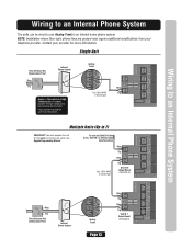
... 4 J5 NC C RELAY 4 NO J4 NC LED 3 C RELAY 3 NO J3 NC C LED 2 NO RELAY 2 NC J1 C LED 1 RELAY 1 See Keypad Programming Manual. EX 1 EX 3Analog EX 4 2 Analog Trunk Tip T R Ring Use 18-24 AWG 2 twisted pair RES J6 Ring TELCO Tip J8 IO Output Board NO LED... NO RELAY 2 NC J1 C LED 1 RELAY 1 Wiring to an Internal Phone System Multiple Units (Up to malfunction. Contact your telephone provider. NOTE: Installation where fiber optic phone lines are present may interfere with the Telco wires, possibly causing the system to 7) IMPORTANT: You must program the unit ID...
... 4 J5 NC C RELAY 4 NO J4 NC LED 3 C RELAY 3 NO J3 NC C LED 2 NO RELAY 2 NC J1 C LED 1 RELAY 1 See Keypad Programming Manual. EX 1 EX 3Analog EX 4 2 Analog Trunk Tip T R Ring Use 18-24 AWG 2 twisted pair RES J6 Ring TELCO Tip J8 IO Output Board NO LED... NO RELAY 2 NC J1 C LED 1 RELAY 1 Wiring to an Internal Phone System Multiple Units (Up to malfunction. Contact your telephone provider. NOTE: Installation where fiber optic phone lines are present may interfere with the Telco wires, possibly causing the system to 7) IMPORTANT: You must program the unit ID...
EL25 - INSTALLATION Manual
Page 21
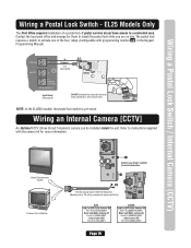
... Cable 1000 Feet Maximum (Monitor with programming number 69 , in the Keypad Programming Manual). One wire per hole. Contact the local post office and arrange for more information. Refer to install the postal lock while you are on site. J7 J6 POSTAL J3 In N.C. ...DO NOT overload the removable terminal block connectors. Wiring a Postal Lock Switch / Internal Camera (CCTV) Wiring a Postal Lock Switch - EL25 Models Only The Post Office requires installation of a postal lock if postal carriers do not have access to activate one of the four relays (Configurable with a .25 volt...
... Cable 1000 Feet Maximum (Monitor with programming number 69 , in the Keypad Programming Manual). One wire per hole. Contact the local post office and arrange for more information. Refer to install the postal lock while you are on site. J7 J6 POSTAL J3 In N.C. ...DO NOT overload the removable terminal block connectors. Wiring a Postal Lock Switch / Internal Camera (CCTV) Wiring a Postal Lock Switch - EL25 Models Only The Post Office requires installation of a postal lock if postal carriers do not have access to activate one of the four relays (Configurable with a .25 volt...

EL25 - INSTALLATION Manual
Page 24
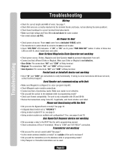
...8226; Check "SYS PWR" LED indicators. Wires to "OPERATE"? • Using an alarm system? See page 7. • Is the remote antenna installed correctly? Make sure Strike or Maglock is correct and device still does not work, contact technical support. The unit is not defective. • Did you...; Check power at Door # terminal(s). If so, see page 9. • Using an alarm system on multiple unit configuration? See the unit's programming manual. • Check connections at source. If "UV" or "OV" are still lit, check transformer and outlet. If either of wires. Phone not ...
...8226; Check "SYS PWR" LED indicators. Wires to "OPERATE"? • Using an alarm system? See page 7. • Is the remote antenna installed correctly? Make sure Strike or Maglock is correct and device still does not work, contact technical support. The unit is not defective. • Did you...; Check power at Door # terminal(s). If so, see page 9. • Using an alarm system on multiple unit configuration? See the unit's programming manual. • Check connections at source. If "UV" or "OV" are still lit, check transformer and outlet. If either of wires. Phone not ...
EL25 - QUICK START GUIDE Manual
Page 1
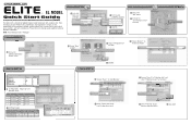
... Enter Country, State/Prov. NOTE: The default password is safe for J407 2 3 4 4. Click the DOORS Tab 2. Please refer to the manuals and/or qualified technician for the Device Pedestrian Gate 3 4 5 4 Select "Pedestrian Group" from the drop-down menu 3 Rename "Door 2" to... Configuration Wizard" button 2 Choose "None" for its intended use. Each application is unique, it is the responsibility of the purchasers, designer, installer and end user to "Pedestrian Gate" and select "Pedestrian Reader" for further information. Select the RELAYS Tab 5. ® 1. Select the DEVICES...
... Enter Country, State/Prov. NOTE: The default password is safe for J407 2 3 4 4. Click the DOORS Tab 2. Please refer to the manuals and/or qualified technician for the Device Pedestrian Gate 3 4 5 4 Select "Pedestrian Group" from the drop-down menu 3 Rename "Door 2" to... Configuration Wizard" button 2 Choose "None" for its intended use. Each application is unique, it is the responsibility of the purchasers, designer, installer and end user to "Pedestrian Gate" and select "Pedestrian Reader" for further information. Select the RELAYS Tab 5. ® 1. Select the DEVICES...

EL25 - QUICK START GUIDE Manual
Page 3
...Quick Start Guide For Multi-Family or single-Family (With Directory Codes) Versa XS This Quick Start is "Manager." 1. Please refer to the manuals and/or qualified technician for the Device 5 6 7 6 Select "Gate Group" from the drop-down menu 7 Click SAVE Click the DOORS Tab...Device 1" to "Gate" and select "Back Door Reader" for further information. Each application is unique, it is the responsibility of the purchasers, designer, installer and end user to ensure that the total control access system is safe for "J400" 5 6 Rename "Device 3" to highlight a typical Multi-Tenant ...
...Quick Start Guide For Multi-Family or single-Family (With Directory Codes) Versa XS This Quick Start is "Manager." 1. Please refer to the manuals and/or qualified technician for the Device 5 6 7 6 Select "Gate Group" from the drop-down menu 7 Click SAVE Click the DOORS Tab...Device 1" to "Gate" and select "Back Door Reader" for further information. Each application is unique, it is the responsibility of the purchasers, designer, installer and end user to ensure that the total control access system is safe for "J400" 5 6 Rename "Device 3" to highlight a typical Multi-Tenant ...
EL25 - QUICK START KEYPAD PROGRAMMING Manual
Page 7
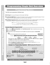
...Single Unit Overview Programming Single Unit Overview Programming Basics The EL25 can be separated with a ( ) are required and must have data entered in this Quickstart Guide) THIS guide will respond with a direct or modem connection, your installation dealer. Note: Some steps are optional, press the... the entire programming sequence, the unit will outline some programming for descriptions and procedures) 2 One or more information, refer to the Manuals and/or your PC must be running Sentex's Windows®-compatible Versa XS software. (Not covered in them . The unit responds ...
...Single Unit Overview Programming Single Unit Overview Programming Basics The EL25 can be separated with a ( ) are required and must have data entered in this Quickstart Guide) THIS guide will respond with a direct or modem connection, your installation dealer. Note: Some steps are optional, press the... the entire programming sequence, the unit will outline some programming for descriptions and procedures) 2 One or more information, refer to the Manuals and/or your PC must be running Sentex's Windows®-compatible Versa XS software. (Not covered in them . The unit responds ...

EL25 - QUICK START KEYPAD PROGRAMMING Manual
Page 13
...= RF Receiver 4 Assign a Door Number (1-4) to the installation manual for the devices to work successfully, you understand the 4 step process needed to an external access control device. (Next Page) EL25 SetUp "Your Settings" EL25 SetUp "Your Settings" Step 1 Assign Each External Access Control...the relay will activate (See Below). Factory Setting: EL25 Keypad Always Assigned to Door 1, No Devices Assigned - 0 1 Press Then Important: A1llthroughe4psmust be equipped with Wiegand reader and radio frequency (RF) modules that allow your installer, this , DO NOT PROCEED. Example A: 1 2...
...= RF Receiver 4 Assign a Door Number (1-4) to the installation manual for the devices to work successfully, you understand the 4 step process needed to an external access control device. (Next Page) EL25 SetUp "Your Settings" EL25 SetUp "Your Settings" Step 1 Assign Each External Access Control...the relay will activate (See Below). Factory Setting: EL25 Keypad Always Assigned to Door 1, No Devices Assigned - 0 1 Press Then Important: A1llthroughe4psmust be equipped with Wiegand reader and radio frequency (RF) modules that allow your installer, this , DO NOT PROCEED. Example A: 1 2...
EL25 Installation Ver. 3.0 Manual
Page 1
All Rights Reserved ® ® ®® Installation Manual for EL MODELS Telephone entry/access control system © 2010 The Chamberlain Group, Inc.
All Rights Reserved ® ® ®® Installation Manual for EL MODELS Telephone entry/access control system © 2010 The Chamberlain Group, Inc.

EL25 Installation Ver. 3.0 Manual
Page 12
NOTE: Installation where fiber optic phone lines are disconnected, the bypass switches must be set to be disconnected without interrupting normal telephone operation. See Keypad Programming Manual. Home Phone Bypass Board for Unit 1 OPERATE BYPASS Bypass Board for Unit 2 OPERATE BYPASS Last Bypass Board BYPASS 4 3 2 1 Ring Tip Ring Tip HOME SYSTEM TELCO 4 3 2 1 ...
NOTE: Installation where fiber optic phone lines are disconnected, the bypass switches must be set to be disconnected without interrupting normal telephone operation. See Keypad Programming Manual. Home Phone Bypass Board for Unit 1 OPERATE BYPASS Bypass Board for Unit 2 OPERATE BYPASS Last Bypass Board BYPASS 4 3 2 1 Ring Tip Ring Tip HOME SYSTEM TELCO 4 3 2 1 ...

EL25 Installation Ver. 3.0 Manual
Page 14
... from your provider for each unit wired in the same conduit. The high voltage wires may require additional modifications from Telco Box. See Keypad Programming Manual. Use 18-24 AWG 2 twisted pair Ring RES Tip J6 Ring TELCO Tip J8 Unit ID 6 Output Board (See page 6) Ring RES... 4 NO J4 NC LED 3 C RELAY 3 NO J3 NC C LED 2 NO RELAY 2 NC J1 C LED 1 RELAY 1 Page 12 Wiring to Dedicated Telco Line NOTE: Installation where fiber optic phone lines are present may interfere with the Telco wires, possibly causing the system to 7) IMPORTANT: You must program the Unit ID...
... from your provider for each unit wired in the same conduit. The high voltage wires may require additional modifications from Telco Box. See Keypad Programming Manual. Use 18-24 AWG 2 twisted pair Ring RES Tip J6 Ring TELCO Tip J8 Unit ID 6 Output Board (See page 6) Ring RES... 4 NO J4 NC LED 3 C RELAY 3 NO J3 NC C LED 2 NO RELAY 2 NC J1 C LED 1 RELAY 1 Page 12 Wiring to Dedicated Telco Line NOTE: Installation where fiber optic phone lines are present may interfere with the Telco wires, possibly causing the system to 7) IMPORTANT: You must program the Unit ID...

EL25 Installation Ver. 3.0 Manual
Page 15
NOTE: Installation where fiber optic phone lines are present may interfere with the Telco wires, possibly causing the system to malfunction. Single Unit Telco Entrance Box Demarcation .... Wiring to an Internal Phone System The units can be wired to 7) IMPORTANT: You must program the unit ID's for more information. See Keypad Programming Manual. Contact your telephone provider. EX 1 EX 3Analog EX 4 2 Analog Trunk Tip T R Ring Use 18-24 AWG 2 twisted pair RES J6 Ring TELCO Tip J8 IO...
NOTE: Installation where fiber optic phone lines are present may interfere with the Telco wires, possibly causing the system to malfunction. Single Unit Telco Entrance Box Demarcation .... Wiring to an Internal Phone System The units can be wired to 7) IMPORTANT: You must program the unit ID's for more information. See Keypad Programming Manual. Contact your telephone provider. EX 1 EX 3Analog EX 4 2 Analog Trunk Tip T R Ring Use 18-24 AWG 2 twisted pair RES J6 Ring TELCO Tip J8 IO...

EL25 Installation Ver. 3.0 Manual
Page 21
...[CCTV] An Optional CCTV (Close Circuit Television) camera can be installed inside the unit. EL25 Models Only The Post Office requires installation of the four relays (Configurable with a .25 volt p-p composite signal sensitivity) EL25 EL2000 Page 19 The postal lock requires a switch to activate one ... Home Entertainment System A Closed Circuit Monitor Contact your dealer/ installer for more information OR RG-59u Coaxial Cable 1000 Feet Maximum (Monitor with programming number 69 , in the Keypad Programming Manual). Contact the local post office and arrange for them to ...
...[CCTV] An Optional CCTV (Close Circuit Television) camera can be installed inside the unit. EL25 Models Only The Post Office requires installation of the four relays (Configurable with a .25 volt p-p composite signal sensitivity) EL25 EL2000 Page 19 The postal lock requires a switch to activate one ... Home Entertainment System A Closed Circuit Monitor Contact your dealer/ installer for more information OR RG-59u Coaxial Cable 1000 Feet Maximum (Monitor with programming number 69 , in the Keypad Programming Manual). Contact the local post office and arrange for them to ...
EL25 Installation Ver. 3.0 Manual
Page 24
...10. • Is Bypass Board switch set to "COM" and "EXT REQ #" connection. If so, see pages 9 and 10. See the unit's programming manual. • Check connections at Relay terminal. Transmitter not working • Did you add the transmitter(s) to a door (program step 60). • Check Wiegand ... voltage and Telco Wires do not share the same conduit. • Use metal conduit, not PVC. See page 7. • Is the remote antenna installed correctly? See page 7. • Check that wires are lit, press "PWR MON RST" button. No Power To Unit • Check power at source...
...10. • Is Bypass Board switch set to "COM" and "EXT REQ #" connection. If so, see pages 9 and 10. See the unit's programming manual. • Check connections at Relay terminal. Transmitter not working • Did you add the transmitter(s) to a door (program step 60). • Check Wiegand ... voltage and Telco Wires do not share the same conduit. • Use metal conduit, not PVC. See page 7. • Is the remote antenna installed correctly? See page 7. • Check that wires are lit, press "PWR MON RST" button. No Power To Unit • Check power at source...

