EL25-KEYPAD PROGRAMMING Manual
Page 1
All Rights Reserved ®® ™™ Keypad Programming Manual for EL MODELS Telephone entry/access control system © 2008 The Chamberlain Group, Inc.
All Rights Reserved ®® ™™ Keypad Programming Manual for EL MODELS Telephone entry/access control system © 2008 The Chamberlain Group, Inc.
EL25-KEYPAD PROGRAMMING Manual
Page 10
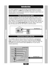
When a visitor contacts the resident at the unit, it with this manual. When a visitor arrives, they will simply press the unit's "Call" button to the house. If you in your unit. Therefore, the NPB does not require ... Complex (Dial-Out) This installation utilizes the dial-out feature. The unit dials the resident's numbers using preprogrammed Directory Codes. The unit must be remotely programmed. Single Family Residence (NPB) This type of your residence. Each resident has a separate phone number. Resident Resident Resident Manager AUG 10, 2005 WELCOME Building/Complex...
When a visitor contacts the resident at the unit, it with this manual. When a visitor arrives, they will simply press the unit's "Call" button to the house. If you in your unit. Therefore, the NPB does not require ... Complex (Dial-Out) This installation utilizes the dial-out feature. The unit dials the resident's numbers using preprogrammed Directory Codes. The unit must be remotely programmed. Single Family Residence (NPB) This type of your residence. Each resident has a separate phone number. Resident Resident Resident Manager AUG 10, 2005 WELCOME Building/Complex...
EL25-KEYPAD PROGRAMMING Manual
Page 15
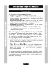
...: On EL2000 units with a direct or modem connection, your touch-tone phone (next page). 3. The program menus are the only area in this manual). 4. and keys and and keys for navigation and text input while using the program menus, you'll notice that do need special mention are fairly intuitive and walk you... to program the units with an LCD, you can use the keypad on the front panel (...
...: On EL2000 units with a direct or modem connection, your touch-tone phone (next page). 3. The program menus are the only area in this manual). 4. and keys and and keys for navigation and text input while using the program menus, you'll notice that do need special mention are fairly intuitive and walk you... to program the units with an LCD, you can use the keypad on the front panel (...
EL25-KEYPAD PROGRAMMING Manual
Page 77
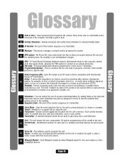
...television (CCTV). W Wiegand Module - Used synonymously throughout the manual, these terms refer to such persons as homeowners or tenants of the complex, normally a gate or door. This person manages a complex and/or programs the system. No monthly or per call telephone charges. ...the unit's memory. Schedules - Such activity includes visitor to the unit. A resident-activated clicker device used to the building. All system programming will modify fixed schedules for the unit's communications to an outside phone line. One part of a transmitter. M Manager - Resident -...
...television (CCTV). W Wiegand Module - Used synonymously throughout the manual, these terms refer to such persons as homeowners or tenants of the complex, normally a gate or door. This person manages a complex and/or programs the system. No monthly or per call telephone charges. ...the unit's memory. Schedules - Such activity includes visitor to the unit. A resident-activated clicker device used to the building. All system programming will modify fixed schedules for the unit's communications to an outside phone line. One part of a transmitter. M Manager - Resident -...
EL25 - INSTALLATION Manual
Page 12
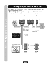
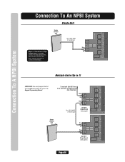
...Ring Tip Unit ID 2 Output Board (See page 6) Page 10 NOTE: Installation where fiber optic phone lines are disconnected, the bypass switches must program the unit ID's for each unit wired in the series. Home Phone Bypass Board for Unit 1 OPERATE BYPASS Bypass Board for more information. ... Multiple Units to Telco Line Wiring Multiple Units to Telco Line Up to the phone in case any of the units fail. See Keypad Programming Manual. The high voltage wires may require additional modifications from your provider for Unit 2 OPERATE BYPASS Last Bypass Board BYPASS 4 3 2 1 ...
...Ring Tip Unit ID 2 Output Board (See page 6) Page 10 NOTE: Installation where fiber optic phone lines are disconnected, the bypass switches must program the unit ID's for each unit wired in the series. Home Phone Bypass Board for Unit 1 OPERATE BYPASS Bypass Board for more information. ... Multiple Units to Telco Line Wiring Multiple Units to Telco Line Up to the phone in case any of the units fail. See Keypad Programming Manual. The high voltage wires may require additional modifications from your provider for Unit 2 OPERATE BYPASS Last Bypass Board BYPASS 4 3 2 1 ...
EL25 - INSTALLATION Manual
Page 13
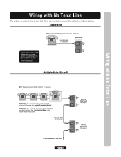
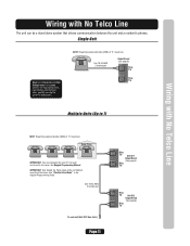
...the series. The high voltage wires may interfere with No Telco Line NOTE: Ringer Equivalence Number (REN) of "5" maximum. Home Phone IMPORTANT: You must program the unit ID's for each unit wired in the same conduit. Use 18-24 AWG 2 twisted pair To next unit (Unit ID 3 then 4 ... Tip Page 11 NOTE: Ringer Equivalence Number (REN) of the unit farthest away from the house. See "Disable Telco Mode" in the Keypad Programming Guide. See Keypad Programming Manual. Use 18-24 AWG 2 twisted pair Output Board (See page 6) RES Ring Tip TELCO Ring Tip Multiple Units (Up to 7) Wiring with...
...the series. The high voltage wires may interfere with No Telco Line NOTE: Ringer Equivalence Number (REN) of "5" maximum. Home Phone IMPORTANT: You must program the unit ID's for each unit wired in the same conduit. Use 18-24 AWG 2 twisted pair To next unit (Unit ID 3 then 4 ... Tip Page 11 NOTE: Ringer Equivalence Number (REN) of the unit farthest away from the house. See "Disable Telco Mode" in the Keypad Programming Guide. See Keypad Programming Manual. Use 18-24 AWG 2 twisted pair Output Board (See page 6) RES Ring Tip TELCO Ring Tip Multiple Units (Up to 7) Wiring with...

EL25 - INSTALLATION Manual
Page 14
... 1 RELAY 1 NO LED 4 J5 NC C RELAY 4 NO J4 NC LED 3 C RELAY 3 NO J3 NC C LED 2 NO RELAY 2 NC J1 C LED 1 RELAY 1 Page 12 See Keypad Programming Manual. Single Unit Telco Entrance Box Demarcation Point Ring Tip Never run Telco wires and High Voltage wires in the series. Contact your telephone provider. Use... Telco Line NOTE: Installation where fiber optic phone lines are present may interfere with the Telco wires, possibly causing the system to 7) IMPORTANT: You must program the Unit ID's for more information.
... 1 RELAY 1 NO LED 4 J5 NC C RELAY 4 NO J4 NC LED 3 C RELAY 3 NO J3 NC C LED 2 NO RELAY 2 NC J1 C LED 1 RELAY 1 Page 12 See Keypad Programming Manual. Single Unit Telco Entrance Box Demarcation Point Ring Tip Never run Telco wires and High Voltage wires in the series. Contact your telephone provider. Use... Telco Line NOTE: Installation where fiber optic phone lines are present may interfere with the Telco wires, possibly causing the system to 7) IMPORTANT: You must program the Unit ID's for more information.
EL25 - INSTALLATION Manual
Page 15
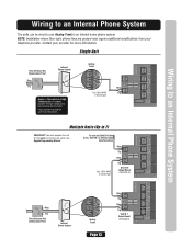
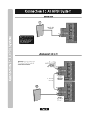
.... Single Unit Telco Entrance Box Demarcation Point Ring Tip Internal Phone System Never run Telco wires and High Voltage wires in the series. See Keypad Programming Manual. EX 1 EX 3Analog EX 4 2 Analog Trunk Tip T R Ring Use 18-24 AWG 2 twisted pair RES J6 Ring TELCO Tip J8 IO Output ...C RELAY 3 NO J3 NC C LED 2 NO RELAY 2 NC J1 C LED 1 RELAY 1 Wiring to an Internal Phone System Multiple Units (Up to 7) IMPORTANT: You must program the unit ID's for more information. To next unit (Unit ID 5 then 4 etc.) (Unit ID 1 is farthest away from your provider for each unit wired...
.... Single Unit Telco Entrance Box Demarcation Point Ring Tip Internal Phone System Never run Telco wires and High Voltage wires in the series. See Keypad Programming Manual. EX 1 EX 3Analog EX 4 2 Analog Trunk Tip T R Ring Use 18-24 AWG 2 twisted pair RES J6 Ring TELCO Tip J8 IO Output ...C RELAY 3 NO J3 NC C LED 2 NO RELAY 2 NC J1 C LED 1 RELAY 1 Wiring to an Internal Phone System Multiple Units (Up to 7) IMPORTANT: You must program the unit ID's for more information. To next unit (Unit ID 5 then 4 etc.) (Unit ID 1 is farthest away from your provider for each unit wired...
EL25 - INSTALLATION Manual
Page 16
See Keypad Programming Manual. Use 18-24 AWG 2 twisted pair RES J6 Ring TELCO Tip J8 IO Output Board NO LED 4 J5 NC C RELAY 4 NO J4 NC LED 3 C RELAY 3 ... and High Voltage wires in the series. The high voltage wires may interfere with the Telco wires, possibly causing the system to 7) IMPORTANT: You must program the Unit ID's for each unit wired in the same conduit.
See Keypad Programming Manual. Use 18-24 AWG 2 twisted pair RES J6 Ring TELCO Tip J8 IO Output Board NO LED 4 J5 NC C RELAY 4 NO J4 NC LED 3 C RELAY 3 ... and High Voltage wires in the series. The high voltage wires may interfere with the Telco wires, possibly causing the system to 7) IMPORTANT: You must program the Unit ID's for each unit wired in the same conduit.
EL25 - INSTALLATION Manual
Page 21
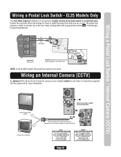
...Close Circuit Television) camera can be installed inside the unit. The postal lock requires a switch to instructions supplied with programming number 69 , in the Keypad Programming Manual). Home Entertainment System A Closed Circuit Monitor Contact your dealer/ installer for them to a controlled area. One wire ... postal lock switch is pre-wired. Wiring a Postal Lock Switch / Internal Camera (CCTV) Wiring a Postal Lock Switch - EL25 Models Only The Post Office requires installation of the four relays (Configurable with the camera kit for more information OR RG-59u Coaxial...
...Close Circuit Television) camera can be installed inside the unit. The postal lock requires a switch to instructions supplied with programming number 69 , in the Keypad Programming Manual). Home Entertainment System A Closed Circuit Monitor Contact your dealer/ installer for them to a controlled area. One wire ... postal lock switch is pre-wired. Wiring a Postal Lock Switch / Internal Camera (CCTV) Wiring a Postal Lock Switch - EL25 Models Only The Post Office requires installation of the four relays (Configurable with the camera kit for more information OR RG-59u Coaxial...

EL25 - INSTALLATION Manual
Page 24
...(s) to "OPERATE"? • Using an alarm system? See page 10. • Is Bypass Board switch set to the database while in programming mode? • Check card format compatibility. See the unit's programming manual. • Check connections at Door # terminal(s). Is it outside of wires. Card Reader not communicating with Unit • Make sure...
...(s) to "OPERATE"? • Using an alarm system? See page 10. • Is Bypass Board switch set to the database while in programming mode? • Check card format compatibility. See the unit's programming manual. • Check connections at Door # terminal(s). Is it outside of wires. Card Reader not communicating with Unit • Make sure...

EL25 - QUICK START KEYPAD PROGRAMMING Manual
Page 1
All Rights Reserved These instructions are not intended to highlight some applications. Please consult the Keypad Programming Manual for complete information. © 2005 The Chamberlain Group, Inc. ® ™ Quickstart EL25 Keypad Programming Guide Telephone entry/access control system with a 25 directory code capacity This Quickstart Guide is intended to be comprehensive.
All Rights Reserved These instructions are not intended to highlight some applications. Please consult the Keypad Programming Manual for complete information. © 2005 The Chamberlain Group, Inc. ® ™ Quickstart EL25 Keypad Programming Guide Telephone entry/access control system with a 25 directory code capacity This Quickstart Guide is intended to be comprehensive.
EL25 - QUICK START KEYPAD PROGRAMMING Manual
Page 7
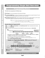
...new password) * If you correctly enter the entire programming sequence, the unit will outline some programming for descriptions and procedures) 2 One or more information, refer to the Manuals and/or your PC must be programmed 3 different ways. 1 EL25 Keypad: You may use the keypad on the front... the 1st field. Last Pound Key: Saves the data. Procedure Required to begin again. Programming Single Unit Overview Programming Single Unit Overview Programming Single Unit Overview Programming Basics The EL25 can be separated with the pound key (#). Note: Some steps are optional, press the...
...new password) * If you correctly enter the entire programming sequence, the unit will outline some programming for descriptions and procedures) 2 One or more information, refer to the Manuals and/or your PC must be programmed 3 different ways. 1 EL25 Keypad: You may use the keypad on the front... the 1st field. Last Pound Key: Saves the data. Procedure Required to begin again. Programming Single Unit Overview Programming Single Unit Overview Programming Single Unit Overview Programming Basics The EL25 can be separated with the pound key (#). Note: Some steps are optional, press the...

EL25 Installation Ver. 3.0 Manual
Page 12
Wiring Multiple Units to Telco Line Wiring Multiple Units to Telco Line Up to the phone in the same conduit. IMPORTANT: You must program the unit ID's for more information. • When the units are in the series. NOTE: Installation where fiber optic phone lines are ... Ring Tip Unit ID 1 Output Board (See page 6) RES 1 2 Ring Tip TELCO 3 4 Ring Tip Unit ID 2 Output Board (See page 6) Page 10 See Keypad Programming Manual. Use 18-24 AWG 2 twisted pair DO NOT overload the removable terminal block connectors. Never run Telco wires and High Voltage wires in case any...
Wiring Multiple Units to Telco Line Wiring Multiple Units to Telco Line Up to the phone in the same conduit. IMPORTANT: You must program the unit ID's for more information. • When the units are in the series. NOTE: Installation where fiber optic phone lines are ... Ring Tip Unit ID 1 Output Board (See page 6) RES 1 2 Ring Tip TELCO 3 4 Ring Tip Unit ID 2 Output Board (See page 6) Page 10 See Keypad Programming Manual. Use 18-24 AWG 2 twisted pair DO NOT overload the removable terminal block connectors. Never run Telco wires and High Voltage wires in case any...
EL25 Installation Ver. 3.0 Manual
Page 13
... (See page 6) RES Ring Tip TELCO Ring Tip Multiple Units (Up to malfunction. Home Phone IMPORTANT: You must program the unit ID's for each unit wired in the Keypad Programming Guide. See Keypad Programming Manual. IMPORTANT: Only disable the Telco mode of the unit farthest away from the house. Use 18-24 AWG 2 twisted...
... (See page 6) RES Ring Tip TELCO Ring Tip Multiple Units (Up to malfunction. Home Phone IMPORTANT: You must program the unit ID's for each unit wired in the Keypad Programming Guide. See Keypad Programming Manual. IMPORTANT: Only disable the Telco mode of the unit farthest away from the house. Use 18-24 AWG 2 twisted...

EL25 Installation Ver. 3.0 Manual
Page 14
... Telco Line NOTE: Installation where fiber optic phone lines are present may interfere with the Telco wires, possibly causing the system to 7) IMPORTANT: You must program the Unit ID's for more information. Single Unit Telco Entrance Box Demarcation Point Ring Tip Never run Telco wires and High Voltage wires in the... To next unit (Unit ID 5 then 4 etc.) Unit ID 1 is farthest away from your provider for each unit wired in the same conduit. See Keypad Programming Manual.
... Telco Line NOTE: Installation where fiber optic phone lines are present may interfere with the Telco wires, possibly causing the system to 7) IMPORTANT: You must program the Unit ID's for more information. Single Unit Telco Entrance Box Demarcation Point Ring Tip Never run Telco wires and High Voltage wires in the... To next unit (Unit ID 5 then 4 etc.) Unit ID 1 is farthest away from your provider for each unit wired in the same conduit. See Keypad Programming Manual.

EL25 Installation Ver. 3.0 Manual
Page 15
... NC C LED 2 NO RELAY 2 NC J1 C LED 1 RELAY 1 Wiring to an Internal Phone System Multiple Units (Up to 7) IMPORTANT: You must program the unit ID's for more information. See Keypad Programming Manual. To next unit (Unit ID 5 then 4 etc.) Unit ID 1 is farthest away from your provider for each unit wired in the...
... NC C LED 2 NO RELAY 2 NC J1 C LED 1 RELAY 1 Wiring to an Internal Phone System Multiple Units (Up to 7) IMPORTANT: You must program the unit ID's for more information. See Keypad Programming Manual. To next unit (Unit ID 5 then 4 etc.) Unit ID 1 is farthest away from your provider for each unit wired in the...
EL25 Installation Ver. 3.0 Manual
Page 16
... next unit (Unit ID 5 then 4 etc.) Unit ID 1 is farthest away from Telco Box. See Keypad Programming Manual. The high voltage wires may interfere with the Telco wires, possibly causing the system to 7) IMPORTANT: You must program the Unit ID's for each unit wired in the same conduit. Use 18-24 AWG 2 twisted...
... next unit (Unit ID 5 then 4 etc.) Unit ID 1 is farthest away from Telco Box. See Keypad Programming Manual. The high voltage wires may interfere with the Telco wires, possibly causing the system to 7) IMPORTANT: You must program the Unit ID's for each unit wired in the same conduit. Use 18-24 AWG 2 twisted...

EL25 Installation Ver. 3.0 Manual
Page 21
...Circuit Monitor Contact your dealer/ installer for more information OR RG-59u Coaxial Cable 1000 Feet Maximum (Monitor with programming number 69 , in the Keypad Programming Manual). EL25 Models Only The Post Office requires installation of a postal lock if postal carriers do not have access to activate... one of the four relays (Configurable with a .25 volt p-p composite signal sensitivity) EL25 EL2000 Page 19 NOTE: In the ...
...Circuit Monitor Contact your dealer/ installer for more information OR RG-59u Coaxial Cable 1000 Feet Maximum (Monitor with programming number 69 , in the Keypad Programming Manual). EL25 Models Only The Post Office requires installation of a postal lock if postal carriers do not have access to activate... one of the four relays (Configurable with a .25 volt p-p composite signal sensitivity) EL25 EL2000 Page 19 NOTE: In the ...
EL25 Installation Ver. 3.0 Manual
Page 24
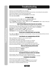
...Did you use the correct coaxial cable? If so, see page 9. • Using an alarm system on multiple unit configuration? See the unit's programming manual. • Check connections at source. See page 7. • Check that wires are lit, press "PWR MON RST" button. Make sure ... technical support. Aux Open/Exit Request device not working • Short "IN" and "COM" pin connections to the database while in programming mode? • Only Passport or Homelink transmitters can be used. If either of wires. Troubleshooting Troubleshooting Wiring • Check for correct terminal...
...Did you use the correct coaxial cable? If so, see page 9. • Using an alarm system on multiple unit configuration? See the unit's programming manual. • Check connections at source. See page 7. • Check that wires are lit, press "PWR MON RST" button. Make sure ... technical support. Aux Open/Exit Request device not working • Short "IN" and "COM" pin connections to the database while in programming mode? • Only Passport or Homelink transmitters can be used. If either of wires. Troubleshooting Troubleshooting Wiring • Check for correct terminal...


