LiftMaster DJ Research
Related Manual Pages


Similar Questions

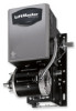
Garage Door Opener Model
How do I know if I have a 3255 or 3255-2M garage door opener?
How do I know if I have a 3255 or 3255-2M garage door opener?
(Posted by ericoster1 3 years ago)

Problem Setting Up 2 Kpr2000 Units On One Access Gate
Can only set both units wired separetly to open electric lock on fail secure. neither will activate ...
Can only set both units wired separetly to open electric lock on fail secure. neither will activate ...
(Posted by klique 9 years ago)
