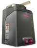
CSW24V Quick Start Guide Manual
Page 1
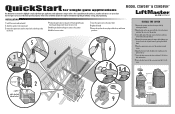
... 1 Remove the operator arm from the gate hinge center). Refer to the installation manual for single gate applications MODEL CSW24V™ & CSW24VH™ This QuickStart is the responsibility of the purchaser, installer and end user to highlight a single right-hand gate application. INSTALLATION 1 Install the concrete pad and conduit. 2 Attach the operator to the concrete pad...
... 1 Remove the operator arm from the gate hinge center). Refer to the installation manual for single gate applications MODEL CSW24V™ & CSW24VH™ This QuickStart is the responsibility of the purchaser, installer and end user to highlight a single right-hand gate application. INSTALLATION 1 Install the concrete pad and conduit. 2 Attach the operator to the concrete pad...
CSW24V Quick Start Guide Manual
Page 2
... information regarding a 240 Vac or solar application refer to the installation manual. 1 Turn off the solid object, reduce the force setting...open or close . For continued protection against fire and electrocution: • DISCONNECT power and battery BEFORE installing or servicing operator. TO BEGIN LIMIT 4 Press and hold one of the MOVE GATE button to ...wires from the entrapment protection device to the Inputs on the OPEN EYES/EDGE terminal. 2 EARTH GROUND ROD 1 Install the earth ground rod within 3 feet of the operator. 2 Run wire from the main power source circuit breaker...
... information regarding a 240 Vac or solar application refer to the installation manual. 1 Turn off the solid object, reduce the force setting...open or close . For continued protection against fire and electrocution: • DISCONNECT power and battery BEFORE installing or servicing operator. TO BEGIN LIMIT 4 Press and hold one of the MOVE GATE button to ...wires from the entrapment protection device to the Inputs on the OPEN EYES/EDGE terminal. 2 EARTH GROUND ROD 1 Install the earth ground rod within 3 feet of the operator. 2 Run wire from the main power source circuit breaker...

CSW24V Installation Manual
Page 1
Visit www.liftmaster.com to locate a professional installing dealer in this manual. UL325 compliant UL991 compliant THIS PRODUCT IS TO BE INSTALLED AND SERVICED BY A TRAINED GATE SYSTEMS TECHNICIAN ONLY. This model is intended for use in Class I, II, III and IV vehicular swing gate applications. CSW24V™ & CSW24VH™ VEHICULAR SWING GATE OPERATOR INSTALLATION MANUAL Your model may look different than the model illustrated in your area. This model is for use on vehicular passage gates ONLY and not intended for use on pedestrian passage gates.
Visit www.liftmaster.com to locate a professional installing dealer in this manual. UL325 compliant UL991 compliant THIS PRODUCT IS TO BE INSTALLED AND SERVICED BY A TRAINED GATE SYSTEMS TECHNICIAN ONLY. This model is intended for use in Class I, II, III and IV vehicular swing gate applications. CSW24V™ & CSW24VH™ VEHICULAR SWING GATE OPERATOR INSTALLATION MANUAL Your model may look different than the model illustrated in your area. This model is for use on vehicular passage gates ONLY and not intended for use on pedestrian passage gates.
CSW24V Installation Manual
Page 3
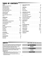
...accompany them carefully. TABLE OF CONTENTS SAFETY 1-7 Safety Symbol and Signal Word Review 1 UL325 Model Classifications 2 Safety Installation Information 3 Gate Construction Information 4 Required Entrapment Protection Devices 5 Important Safety Information 6-7 INTRODUCTION 8-9 Operator Specifications 8 ...10-11 INSTALLATION 12-16 Standard Installation Only 12-13 Compact Installation Only 14-15 Installation Continued 16 PROGRAMMING 26 Remote Controls 26 Erase All Codes 26 FINISH INSTALLATION 27 Install the Cover 27 OPERATION 28 Manual Disconnect 28 ...
...accompany them carefully. TABLE OF CONTENTS SAFETY 1-7 Safety Symbol and Signal Word Review 1 UL325 Model Classifications 2 Safety Installation Information 3 Gate Construction Information 4 Required Entrapment Protection Devices 5 Important Safety Information 6-7 INTRODUCTION 8-9 Operator Specifications 8 ...10-11 INSTALLATION 12-16 Standard Installation Only 12-13 Compact Installation Only 14-15 Installation Continued 16 PROGRAMMING 26 Remote Controls 26 Erase All Codes 26 FINISH INSTALLATION 27 Install the Cover 27 OPERATION 28 Manual Disconnect 28 ...
CSW24V Installation Manual
Page 5
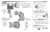
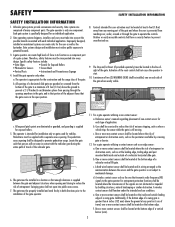
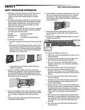
... that transmits radio frequency (RF) signals to the installation of non-contact sensor for an individual application. 2. The operator is prevented from reaching over, under the intended end-use . 9. c. Reference owner's manual regarding placement of the gate operator. 11. c. ...shall be located in the open into account the possible hazards associated with a separate access opening. SAFETY SAFETY INSTALLATION INFORMATION SAFETY INSTALLATION INFORMATION 1. b. Vehicular gate systems provide convenience and security. One or more contact sensors shall be located at ...
... that transmits radio frequency (RF) signals to the installation of non-contact sensor for an individual application. 2. The operator is prevented from reaching over, under the intended end-use . 9. c. Reference owner's manual regarding placement of the gate operator. 11. c. ...shall be located in the open into account the possible hazards associated with a separate access opening. SAFETY SAFETY INSTALLATION INFORMATION SAFETY INSTALLATION INFORMATION 1. b. Vehicular gate systems provide convenience and security. One or more contact sensors shall be located at ...
CSW24V Installation Manual
Page 6
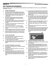
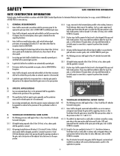
...SLIDE GATES 3.1 The following provisions shall apply to Class 1, Class II and Class III vehicular horizontal swing gates: 4.1.1 Gates shall be designed, constructed and installed so as not to create an entrapment area between a 1.1 1.2 1.3 1.4 1.5 1.6 1.7 1.8 Gates shall be required to limit travel to ASTM F2200 ... the designed fully open position or the fully closed positions. An existing gate latch shall be disabled when a manually operated gate is to be automated shall be installed at either the fully open and fully closed position, shall not exceed 2 1/4 inches (57 mm), refer ...
...SLIDE GATES 3.1 The following provisions shall apply to Class 1, Class II and Class III vehicular horizontal swing gates: 4.1.1 Gates shall be designed, constructed and installed so as not to create an entrapment area between a 1.1 1.2 1.3 1.4 1.5 1.6 1.7 1.8 Gates shall be required to limit travel to ASTM F2200 ... the designed fully open position or the fully closed positions. An existing gate latch shall be disabled when a manually operated gate is to be automated shall be installed at either the fully open and fully closed position, shall not exceed 2 1/4 inches (57 mm), refer ...
CSW24V Installation Manual
Page 9
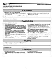
...away from a moving . • KEEP GATES PROPERLY MAINTAINED. Read the owner's manual. For continued protection against fire and electrocution: • DISCONNECT power (AC or solar and battery) BEFORE installing or servicing operator. NOTE: The operator should be performed until disconnecting the electrical ... the risk of SEVERE INJURY or DEATH: • READ AND FOLLOW ALL INSTRUCTIONS. • ANY maintenance to persons use ONLY LiftMaster part 29-NP712 for replacement batteries. • SAVE THESE INSTRUCTIONS. • ALWAYS wear protective gloves and eye protection when changing...
...away from a moving . • KEEP GATES PROPERLY MAINTAINED. Read the owner's manual. For continued protection against fire and electrocution: • DISCONNECT power (AC or solar and battery) BEFORE installing or servicing operator. NOTE: The operator should be performed until disconnecting the electrical ... the risk of SEVERE INJURY or DEATH: • READ AND FOLLOW ALL INSTRUCTIONS. • ANY maintenance to persons use ONLY LiftMaster part 29-NP712 for replacement batteries. • SAVE THESE INSTRUCTIONS. • ALWAYS wear protective gloves and eye protection when changing...
CSW24V Installation Manual
Page 11
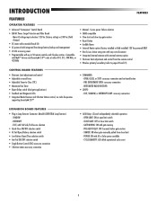
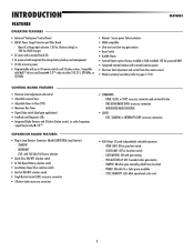
... • Slow-start and slow-stop gate motion • Reset Button • Audible Alarm • Internal Heater option (factory installed or field installed) 120 Vac powered ONLY • Non-Scissor Action swing arm with easy arm disconnect • Integrated internal antenna with up to ...option • Electronic limit adjustment and control from close limit switch - FIRE DEPARTMENT OPEN: accessory connection - TAMPER: ON when gate manually pulled from the remote control • Wireless primary/secondary (refer to pages 20 and 21) CONTROL BOARD FEATURES • Electronic Limit ...
... • Slow-start and slow-stop gate motion • Reset Button • Audible Alarm • Internal Heater option (factory installed or field installed) 120 Vac powered ONLY • Non-Scissor Action swing arm with easy arm disconnect • Integrated internal antenna with up to ...option • Electronic limit adjustment and control from close limit switch - FIRE DEPARTMENT OPEN: accessory connection - TAMPER: ON when gate manually pulled from the remote control • Wireless primary/secondary (refer to pages 20 and 21) CONTROL BOARD FEATURES • Electronic Limit ...
CSW24V Installation Manual
Page 30
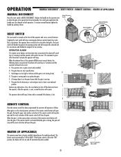
.... Remove any obstructions. When the gate is on both operators. HEATER (IF APPLICABLE) The operator may have a heater installed, depending on the operator arm to allow the gate to be reset after the initial 5 minutes the operator will beep. ! OPERATION... is left in the present position and will operate as follows: When gate is incorrectly installed. E. D ! C. The gate hits the driveway or curb and gets stuck or bent in the closed manually. OPERATOR ALARM If a contact sensor detects an obstruction twice consecutively the alarm will sound ...
.... Remove any obstructions. When the gate is on both operators. HEATER (IF APPLICABLE) The operator may have a heater installed, depending on the operator arm to allow the gate to be reset after the initial 5 minutes the operator will beep. ! OPERATION... is left in the present position and will operate as follows: When gate is incorrectly installed. E. D ! C. The gate hits the driveway or curb and gets stuck or bent in the closed manually. OPERATOR ALARM If a contact sensor detects an obstruction twice consecutively the alarm will sound ...

CSW24V Manual
Page 1
CSL24V™ & CSL24VH™ VEHICULAR SLIDE GATE OPERATOR INSTALLATION MANUAL Your model may look different than the model illustrated in your area. Visit www.liftmaster.com to locate a professional installing dealer in this manual. This model is for use on vehicular passage gates ONLY and not intended for use on pedestrian passage gates. UL325 compliant UL991 compliant THIS PRODUCT IS TO BE INSTALLED AND SERVICED BY A TRAINED GATE SYSTEMS TECHNICIAN ONLY. This model is intended for use in Class I, II, III and IV vehicular slide gate applications.
CSL24V™ & CSL24VH™ VEHICULAR SLIDE GATE OPERATOR INSTALLATION MANUAL Your model may look different than the model illustrated in your area. Visit www.liftmaster.com to locate a professional installing dealer in this manual. This model is for use on vehicular passage gates ONLY and not intended for use on pedestrian passage gates. UL325 compliant UL991 compliant THIS PRODUCT IS TO BE INSTALLED AND SERVICED BY A TRAINED GATE SYSTEMS TECHNICIAN ONLY. This model is intended for use in Class I, II, III and IV vehicular slide gate applications.
CSW24V Manual
Page 3
IMPORTANT NOTE • BEFORE attempting to install, operate or maintain the operator, you must read and fully understand this manual and follow all safety instructions. • DO NOT attempt repair or service of damage to your gate operator unless you see these Safety Symbols and ...
IMPORTANT NOTE • BEFORE attempting to install, operate or maintain the operator, you must read and fully understand this manual and follow all safety instructions. • DO NOT attempt repair or service of damage to your gate operator unless you see these Safety Symbols and ...
CSW24V Manual
Page 5
... Mesh • Instructional and Precautionary Signage 4. For a gate operator utilizing a non-contact sensor: a. c. SAFETY SAFETY INSTALLATION INFORMATION SAFETY INSTALLATION INFORMATION 1. Specific safety features include: • Gate Edges • Photoelectric Sensors • Vertical Posts • Guards ... structures when opening shall be located where the transmission of the signals are comprised of application. Reference owner's manual regarding placement of a gate system. d. Therefore, safety features must take into every design. Swinging gates shall...
... Mesh • Instructional and Precautionary Signage 4. For a gate operator utilizing a non-contact sensor: a. c. SAFETY SAFETY INSTALLATION INFORMATION SAFETY INSTALLATION INFORMATION 1. Specific safety features include: • Gate Edges • Photoelectric Sensors • Vertical Posts • Guards ... structures when opening shall be located where the transmission of the signals are comprised of application. Reference owner's manual regarding placement of a gate system. d. Therefore, safety features must take into every design. Swinging gates shall...
CSW24V Manual
Page 6
... 4.1 The following provisions shall apply to Class IV vehicular horizontal slide 1.5 An existing gate latch shall be disabled when a manually operated gate is gates: retrofitted with sufficient lateral stability to assure that their intended function. 1.9 A pedestrian gate shall not...horizontally or vertically project no more than is disconnected. SAFETY GATE CONSTRUCTION INFORMATION GATE CONSTRUCTION INFORMATION Vehicular gates should be installed in accordance with security related parameters specific to the application in question. 4 F2200 for additional gate types. shall ...
... 4.1 The following provisions shall apply to Class IV vehicular horizontal slide 1.5 An existing gate latch shall be disabled when a manually operated gate is gates: retrofitted with sufficient lateral stability to assure that their intended function. 1.9 A pedestrian gate shall not...horizontally or vertically project no more than is disconnected. SAFETY GATE CONSTRUCTION INFORMATION GATE CONSTRUCTION INFORMATION Vehicular gates should be installed in accordance with security related parameters specific to the application in question. 4 F2200 for additional gate types. shall ...
CSW24V Manual
Page 9
...and connected in BOTH the open and close gate cycles. Read the owner's manual. MAINTENANCE AND OPERATION • Locate entrapment protection devices to persons use ONLY LiftMaster part 29-NP712 for replacement batteries. • SAVE THESE INSTRUCTIONS. • ...manual disconnect release ONLY when the gate is properly adjusted and there are no obstructions to gate travel , retest the gate operator. Have a qualified service person make repairs to gate hardware. • ALL maintenance MUST be performed by a LiftMaster professional. • Activate gate ONLY when it can be installed...
...and connected in BOTH the open and close gate cycles. Read the owner's manual. MAINTENANCE AND OPERATION • Locate entrapment protection devices to persons use ONLY LiftMaster part 29-NP712 for replacement batteries. • SAVE THESE INSTRUCTIONS. • ...manual disconnect release ONLY when the gate is properly adjusted and there are no obstructions to gate travel , retest the gate operator. Have a qualified service person make repairs to gate hardware. • ALL maintenance MUST be performed by a LiftMaster professional. • Activate gate ONLY when it can be installed...
CSW24V Manual
Page 11
...compatible • Slow-start and slow-stop gate motion • Reset Switch • Audible Alarm • Internal Heater option (factory installed or field installed) 120 Vac powered ONLY • Integrated internal antenna with Fail Safe/Fail Secure selection • Quick-Close ON/OFF selection switch ...on-board button - GATE MOVING: ON with AC or Solar power available - POWER: ON with gate moving - TAMPER: ON when gate manually pulled from the remote control • Wireless primary/secondary (refer to pages 17-18) CONTROL BOARD FEATURES • Electronic Limit adjustment and...
...compatible • Slow-start and slow-stop gate motion • Reset Switch • Audible Alarm • Internal Heater option (factory installed or field installed) 120 Vac powered ONLY • Integrated internal antenna with Fail Safe/Fail Secure selection • Quick-Close ON/OFF selection switch ...on-board button - GATE MOVING: ON with AC or Solar power available - POWER: ON with gate moving - TAMPER: ON when gate manually pulled from the remote control • Wireless primary/secondary (refer to pages 17-18) CONTROL BOARD FEATURES • Electronic Limit adjustment and...

CSW24V Manual
Page 15
...ground. Vent Plug Pin 13 Chain should not be too tight or have excessive slack. INSTALLATION STANDARD INSTALLATION ONLY + REAR INSTALLATION ONLY STANDARD INSTALLATION ONLY DO NOT run the operator until instructed. 1 Manually open the gate and line up the rear bracket so the chain will be level with...chain length. 5 3 2 Idler Pulley MUST have no more than 1 inch of sag for every 10 feet of chain length. 2 4 REAR INSTALLATION ONLY DO NOT run the operator until instructed. Weld the rear bracket in this position. 3 Route the chain through the operator. 5 Connect the ...
...ground. Vent Plug Pin 13 Chain should not be too tight or have excessive slack. INSTALLATION STANDARD INSTALLATION ONLY + REAR INSTALLATION ONLY STANDARD INSTALLATION ONLY DO NOT run the operator until instructed. 1 Manually open the gate and line up the rear bracket so the chain will be level with...chain length. 5 3 2 Idler Pulley MUST have no more than 1 inch of sag for every 10 feet of chain length. 2 4 REAR INSTALLATION ONLY DO NOT run the operator until instructed. Weld the rear bracket in this position. 3 Route the chain through the operator. 5 Connect the ...

CSW24V Manual
Page 27
...operator will operate as mud, rocks, dirt, etc. RESET/DISCONNECT NORMAL OPERATION B D HEATER (IF APPLICABLE) The operator may have a heater installed, depending on the model purchased. Toggling the reset switch will energize the solenoid lock for two minutes and disable the maglock for two minutes....5 minutes) and the operator will need to shut off automatically when needed. B. D. If the heater switch is left in the closed manually. To resume normal operation press the reset switch to be powered by 120 Vac ONLY. C. When the inherent force of the remote control ...
...operator will operate as mud, rocks, dirt, etc. RESET/DISCONNECT NORMAL OPERATION B D HEATER (IF APPLICABLE) The operator may have a heater installed, depending on the model purchased. Toggling the reset switch will energize the solenoid lock for two minutes and disable the maglock for two minutes....5 minutes) and the operator will need to shut off automatically when needed. B. D. If the heater switch is left in the closed manually. To resume normal operation press the reset switch to be powered by 120 Vac ONLY. C. When the inherent force of the remote control ...

