CSL24VDC Sell Sheet Manual
Page 2
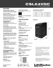
... times, even after using manual disconnect. LED DIAGNOSTIC DISPLAY Easy-to 140°F (60C). DIMENSIONS ACCESSORY POWER 24VDC 500mA output. Switched and unswitched power. WORM GEAR REDUCTION Commercial oil bath gearbox providing a 30:1 worm gear reduction. LiftMaster gate operators comply with six... settings each wing and adjusts the speed as necessary to ensure primary gate closes last, avoiding potential damage to the gate. CSL24VDC COMMERCIAL HIGH TRAFFIC DC SLIDE GATE OPERATOR FEATURES FIRE...
... times, even after using manual disconnect. LED DIAGNOSTIC DISPLAY Easy-to 140°F (60C). DIMENSIONS ACCESSORY POWER 24VDC 500mA output. Switched and unswitched power. WORM GEAR REDUCTION Commercial oil bath gearbox providing a 30:1 worm gear reduction. LiftMaster gate operators comply with six... settings each wing and adjusts the speed as necessary to ensure primary gate closes last, avoiding potential damage to the gate. CSL24VDC COMMERCIAL HIGH TRAFFIC DC SLIDE GATE OPERATOR FEATURES FIRE...

CSL24VDC Solar Chart Manual
Page 3
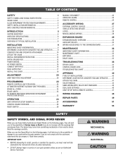
System voltage 12v Main board with no radios learned (mA) 4.2 One or more LiftMaster® transmitters learned (mA) +1.5 MyQ® device or wireless dual gate learned (mA) +3.9 Expansion board (mA) +18.5 Per loop detector LOOPDETLM (up current draw by ...! 73 82 55 64 51 59 #NUM! #NUM! 3 #NUM! 100 100 90 100 85 100 22 #NUM! 39 #NUM! For full details please reference the manual. 3 not available 2 3 1 2 1 Dual gate solar cycles per day Battery current draw (mA) 6 25 10W Solar Panel 30 50 100 6 25 20W Solar Panel 30 100...
System voltage 12v Main board with no radios learned (mA) 4.2 One or more LiftMaster® transmitters learned (mA) +1.5 MyQ® device or wireless dual gate learned (mA) +3.9 Expansion board (mA) +18.5 Per loop detector LOOPDETLM (up current draw by ...! 73 82 55 64 51 59 #NUM! #NUM! 3 #NUM! 100 100 90 100 85 100 22 #NUM! 39 #NUM! For full details please reference the manual. 3 not available 2 3 1 2 1 Dual gate solar cycles per day Battery current draw (mA) 6 25 10W Solar Panel 30 50 100 6 25 20W Solar Panel 30 100...
CSL24VDC Installation Manual
Page 3
... GATES ONLY 17 INSTALL THE COVER 19 ADJUSTMENT 20 LIMIT AND FORCE ADJUSTMENT 20 PROGRAMMING 22 REMOTE CONTROLS (NOT PROVIDED 22 LIFTMASTER INTERNET GATEWAY (NOT PROVIDED 23 ERASE ALL CODES 23 ERASE LIMITS 23 TO REMOVE AND ERASE MONITORED ENTRAPMENT PROTECTION DEVICES 23 ...OPERATION 24 GATE OPERATOR SETUP EXAMPLES 24 CONTROL BOARD OVERVIEW 25 RESET SWITCH 26 MANUAL DISCONNECT 26 OPERATOR ALARM 26 REMOTE CONTROL 26 ACCESSORY WIRING 27 EXTERNAL CONTROL DEVICES 27 VEHICLE DETECTION DEVICES 27 LOCKS 28 ...
... GATES ONLY 17 INSTALL THE COVER 19 ADJUSTMENT 20 LIMIT AND FORCE ADJUSTMENT 20 PROGRAMMING 22 REMOTE CONTROLS (NOT PROVIDED 22 LIFTMASTER INTERNET GATEWAY (NOT PROVIDED 23 ERASE ALL CODES 23 ERASE LIMITS 23 TO REMOVE AND ERASE MONITORED ENTRAPMENT PROTECTION DEVICES 23 ...OPERATION 24 GATE OPERATOR SETUP EXAMPLES 24 CONTROL BOARD OVERVIEW 25 RESET SWITCH 26 MANUAL DISCONNECT 26 OPERATOR ALARM 26 REMOTE CONTROL 26 ACCESSORY WIRING 27 EXTERNAL CONTROL DEVICES 27 VEHICLE DETECTION DEVICES 27 LOCKS 28 ...

CSL24VDC Installation Manual
Page 4
... monthly. Failure to adjust and retest the gate operator properly can increase the risk of device shall not be installed with Type A. Read the owner's manual. RESIDENTIAL VEHICULAR GATE OPERATOR I - COMMERCIAL/GENERAL ACCESS VEHICULAR GATE OPERATOR II A vehicular gate operator (or system) intended for use in a guarded industrial location or building...
... monthly. Failure to adjust and retest the gate operator properly can increase the risk of device shall not be installed with Type A. Read the owner's manual. RESIDENTIAL VEHICULAR GATE OPERATOR I - COMMERCIAL/GENERAL ACCESS VEHICULAR GATE OPERATOR II A vehicular gate operator (or system) intended for use in a guarded industrial location or building...

CSL24VDC Installation Manual
Page 5
... of the reset control shall not cause the operator to the installation of the vehicular gate. 6. For a gate operator utilizing a non-contact sensor: a. Reference owner's manual regarding placement of non-contact sensor for the construction and the usage class of application. c. Additionally, if the bottom edge of a swing gate is appropriate...
... of the reset control shall not cause the operator to the installation of the vehicular gate. 6. For a gate operator utilizing a non-contact sensor: a. Reference owner's manual regarding placement of non-contact sensor for the construction and the usage class of application. c. Additionally, if the bottom edge of a swing gate is appropriate...

CSL24VDC Installation Manual
Page 6
... 8 feet (2.44 m) above grade and for barbed wire shall not be less than 6 feet (1.83 m) above grade. 1.5 An existing gate latch shall be disabled when a manually operated gate is retrofitted with a powered gate operator. 1.6 A gate latch shall not be installed on an automatically operated gate. 1.7 Protrusions shall not be permitted on...
... 8 feet (2.44 m) above grade and for barbed wire shall not be less than 6 feet (1.83 m) above grade. 1.5 An existing gate latch shall be disabled when a manually operated gate is retrofitted with a powered gate operator. 1.6 A gate latch shall not be installed on an automatically operated gate. 1.7 Protrusions shall not be permitted on...

CSL24VDC Installation Manual
Page 10
... national and local codes for proper depth Water Tight Conduit (Not provided) NOTE: Power and control wiring MUST be run in the back of the manual for proper depth Water Tight Conduit (Not provided) NOTE: Power and control wiring MUST be run in separate conduits. 8
... national and local codes for proper depth Water Tight Conduit (Not provided) NOTE: Power and control wiring MUST be run in the back of the manual for proper depth Water Tight Conduit (Not provided) NOTE: Power and control wiring MUST be run in separate conduits. 8

CSL24VDC Installation Manual
Page 13
... to the Appendix for every 10 feet of chain length. Route the chain through the operator. 4. Chain should have excessive slack. 5. Vent Plug Pin 11 Manually open the gate and line up the rear bracket so the chain will be level with the idler pulley and parallel to the brackets using... position. 2. Connect the chain to the ground. Remove the pin from the vent plug on the gear box. DO NOT run the operator until instructed. 1. Manually close the gate and line up the front bracket so the chain will be too tight or have no more than 1 inch of sag for...
... to the Appendix for every 10 feet of chain length. Route the chain through the operator. 4. Chain should have excessive slack. 5. Vent Plug Pin 11 Manually open the gate and line up the rear bracket so the chain will be level with the idler pulley and parallel to the brackets using... position. 2. Connect the chain to the ground. Remove the pin from the vent plug on the gear box. DO NOT run the operator until instructed. 1. Manually close the gate and line up the front bracket so the chain will be too tight or have no more than 1 inch of sag for...

CSL24VDC Installation Manual
Page 15
... photoelectric sensor or edge sensor entrapment protection for the open position and resets the Timer-to the wiring diagram or the specific entrapment protection device manual for 4 seconds then stop . Refer to -Close. This input will be a single, whole piece of wire. INSTALLATION STEP 4 continued... OPEN EYES/EDGE (2 Terminals) The OPEN...
... photoelectric sensor or edge sensor entrapment protection for the open position and resets the Timer-to the wiring diagram or the specific entrapment protection device manual for 4 seconds then stop . Refer to -Close. This input will be a single, whole piece of wire. INSTALLATION STEP 4 continued... OPEN EYES/EDGE (2 Terminals) The OPEN...
CSL24VDC Installation Manual
Page 26
...Fire Dept Open input Heater Accessory (Model HTR) RESIDENTIAL COMMERCIAL/GENERAL COMMERCIAL ACCESS INDUSTRIAL Normally set to know when system is manually tampered with by being pushed off of close limit. Normally set to indicate if gate is charging batteries (i.e. opening . ...etc.). Gate Motion Aux Relay Out - Normally set to determine operator cycles. If powered from battery and battery is manually tampered with SAMS (Sequence Access Management Access Management System). closing gate. Set to the site requirements, including all necessary...
...Fire Dept Open input Heater Accessory (Model HTR) RESIDENTIAL COMMERCIAL/GENERAL COMMERCIAL ACCESS INDUSTRIAL Normally set to know when system is manually tampered with by being pushed off of close limit. Normally set to indicate if gate is charging batteries (i.e. opening . ...etc.). Gate Motion Aux Relay Out - Normally set to determine operator cycles. If powered from battery and battery is manually tampered with SAMS (Sequence Access Management Access Management System). closing gate. Set to the site requirements, including all necessary...
CSL24VDC Installation Manual
Page 27
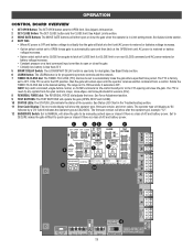
...'s). 8 REVERSAL FORCE dial: The REVERSAL FORCE dial adjusts the force. The TTC is reset by a "24" which indicates the operator type as CSL24VDC. See Adjust Limits section. 3 MOVE GATE Buttons: The MOVE GATE buttons will latch at a limit until AC power is restored or batteries voltage increases...DELAY Switch: The LOCK/BIPART DELAY switch is 0 to automatically close the gate after the operator type, example "1.2". 12 BACKDRIVE Switch: Set to MANUAL will close the gate when the operator is OFF. See Bipart Delay section. 6 LEARN Button: The LEARN button is for dual gates. The range...
...'s). 8 REVERSAL FORCE dial: The REVERSAL FORCE dial adjusts the force. The TTC is reset by a "24" which indicates the operator type as CSL24VDC. See Adjust Limits section. 3 MOVE GATE Buttons: The MOVE GATE buttons will latch at a limit until AC power is restored or batteries voltage increases...DELAY Switch: The LOCK/BIPART DELAY switch is 0 to automatically close the gate after the operator type, example "1.2". 12 BACKDRIVE Switch: Set to MANUAL will close the gate when the operator is OFF. See Bipart Delay section. 6 LEARN Button: The LEARN button is for dual gates. The range...

CSL24VDC Installation Manual
Page 28
..., rocks, dirt, etc. If the remote control is activated while the gate is in the closed manually. Toggling the reset switch will open position, activation of the remote control button will need to be reset: A. MANUAL DISCONNECT Press the reset switch to RESET/DISCONNECT to allow the gate to be opened and...
..., rocks, dirt, etc. If the remote control is activated while the gate is in the closed manually. Toggling the reset switch will open position, activation of the remote control button will need to be reset: A. MANUAL DISCONNECT Press the reset switch to RESET/DISCONNECT to allow the gate to be opened and...

CSL24VDC Installation Manual
Page 32
... with by being pushed close limit. closed relay contacts to their appropriate positions. See below. AUX Relay 1 N.C. ON OFF ON Energizes if gate is manually tampered with 1 LED blinking 1000's, 2 LED blinking 10,000's, 3 LED blinking 100,000's, and simultaneously all the LEDs will sound. AUX RELAY ...1 AUX RELAY 2 30 For an additional audible energized during Energizes 3 seconds before relay cutoff, after AC shutdown. There is manually tampered with barrier gate). CYCLE COUNT * First, note the current Aux Relay switch positions. Warning Light AUX Relay 2 N.C.
... with by being pushed close limit. closed relay contacts to their appropriate positions. See below. AUX Relay 1 N.C. ON OFF ON Energizes if gate is manually tampered with 1 LED blinking 1000's, 2 LED blinking 10,000's, 3 LED blinking 100,000's, and simultaneously all the LEDs will sound. AUX RELAY ...1 AUX RELAY 2 30 For an additional audible energized during Energizes 3 seconds before relay cutoff, after AC shutdown. There is manually tampered with barrier gate). CYCLE COUNT * First, note the current Aux Relay switch positions. Warning Light AUX Relay 2 N.C.

CSL24VDC Installation Manual
Page 34
... THE PATH OF THE MOVING GATE. • The entrance is not moving. • KEEP GATES PROPERLY MAINTAINED. Pedestrians MUST use ONLY LiftMaster part 29-NP712 for replacement batteries. • SAVE THESE INSTRUCTIONS. • ALWAYS wear protective gloves and eye protection when changing the battery...make repairs to gate hardware. • ALL maintenance MUST be performed by a LiftMaster professional. • Activate gate ONLY when it can increase the risk of INJURY or DEATH. • Use the manual disconnect release ONLY when the gate is for proper operation CHECK AT LEAST ONCE EVERY...
... THE PATH OF THE MOVING GATE. • The entrance is not moving. • KEEP GATES PROPERLY MAINTAINED. Pedestrians MUST use ONLY LiftMaster part 29-NP712 for replacement batteries. • SAVE THESE INSTRUCTIONS. • ALWAYS wear protective gloves and eye protection when changing the battery...make repairs to gate hardware. • ALL maintenance MUST be performed by a LiftMaster professional. • Activate gate ONLY when it can increase the risk of INJURY or DEATH. • Use the manual disconnect release ONLY when the gate is for proper operation CHECK AT LEAST ONCE EVERY...

CSL24VDC Installation Manual
Page 39
.... Repair gate as needed. b) Check Stop button is too difficult to move gate, and ensure gate moves easily limit to move a) Use manual disconnect, manually move c) Limits are set correct limits. Gate stops during a) Control (Open, Close) becoming active travel and reverses b) Vehicle loop detector active...the CLOSE limit. Repair gate as needed . Gate closes, but will not open or fully close (slide gate applications only) a) Use manual disconnect, manually move to limit. Operator does not respond to a wired control/command (example: Open, Close, SBC, etc.) a) Check Open and ...
.... Repair gate as needed. b) Check Stop button is too difficult to move gate, and ensure gate moves easily limit to move a) Use manual disconnect, manually move c) Limits are set correct limits. Gate stops during a) Control (Open, Close) becoming active travel and reverses b) Vehicle loop detector active...the CLOSE limit. Repair gate as needed . Gate closes, but will not open or fully close (slide gate applications only) a) Use manual disconnect, manually move to limit. Operator does not respond to a wired control/command (example: Open, Close, SBC, etc.) a) Check Open and ...

CSL24VDC Installation Manual
Page 43
... out the concrete pad. NOTE: This installation will be level with the top idler pulley and parallel to the brackets using the eye bolt hardware. Manually close the gate and align the bottom bracket so the chain will require two extra idler pulleys. Align the top bracket so the chain will...
... out the concrete pad. NOTE: This installation will be level with the top idler pulley and parallel to the brackets using the eye bolt hardware. Manually close the gate and align the bottom bracket so the chain will require two extra idler pulleys. Align the top bracket so the chain will...


