
DC Gate Operators Overview Brochure Manual
Page 1
... Model Number Description LA5001PKGDC 24VDC Residential / Light Commercial Linear Actuator Photo of Gate Operator Security+ 2.0™ 3 Channel Receiver (50 remote capacity) Battery Backup Exceptional Standby Power MyQ® Technology Best-in-Class Solar Performance (with on board radio (2) 7-AH batteries) DC Motor with Soft Start/Stop Common Control Board User Interface Diagnostic Code Display 2 Digit LED Wireless Dual Gate Operation PosiLock® Feature Pre-Motion Warning Alarm Fire Department Compliant (Auto Open (or Push Open Slide Gates)) Electronic Limits / Automatic Force Control...
... Model Number Description LA5001PKGDC 24VDC Residential / Light Commercial Linear Actuator Photo of Gate Operator Security+ 2.0™ 3 Channel Receiver (50 remote capacity) Battery Backup Exceptional Standby Power MyQ® Technology Best-in-Class Solar Performance (with on board radio (2) 7-AH batteries) DC Motor with Soft Start/Stop Common Control Board User Interface Diagnostic Code Display 2 Digit LED Wireless Dual Gate Operation PosiLock® Feature Pre-Motion Warning Alarm Fire Department Compliant (Auto Open (or Push Open Slide Gates)) Electronic Limits / Automatic Force Control...

DC Gate Operators Overview Brochure Manual
Page 2
... or interrupt gate travel if a vehicle is forced off devices at all other times to monitor and control your gate operator and lights with six settings each simplify adding additional features. LiftMaster® Gate Operators Unrivaled Performance, Security and Accessibility Introducing our new LiftMaster DC Gate Operator line up to 20 past events. • Wireless Dual-Gate Operation saves from unsightly driveway scars and expensive wiring. • Auto Force Adjustment reduces call backs. Switch on...
... or interrupt gate travel if a vehicle is forced off devices at all other times to monitor and control your gate operator and lights with six settings each simplify adding additional features. LiftMaster® Gate Operators Unrivaled Performance, Security and Accessibility Introducing our new LiftMaster DC Gate Operator line up to 20 past events. • Wireless Dual-Gate Operation saves from unsightly driveway scars and expensive wiring. • Auto Force Adjustment reduces call backs. Switch on...
CSL24VDC Sell Sheet Manual
Page 2
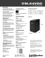
... access. QUICK CLOSE Closes the gate immediately after using manual disconnect. SECURITY+ 2.0™ ON-BOARD RADIO RECEIVER Up to the gate. Does not include added accessory power draw. Switched and unswitched power. CHASSIS Constructed with UL 325 standards. OPERATOR WEIGHT 140 lbs. ONE TOUCH PUSH BUTTON PROGRAMMABLE ELECTRONIC LIMIT SYSTEM Maintains accurate gate position throughout gate travel. SYNCHRONIZED CLOSE Simultaneously closes gates. LiftMaster gate operators comply with 1/4" gold zinc plated steel for excellent heat and corrosion resistance. CSL24VDC COMMERCIAL...
... access. QUICK CLOSE Closes the gate immediately after using manual disconnect. SECURITY+ 2.0™ ON-BOARD RADIO RECEIVER Up to the gate. Does not include added accessory power draw. Switched and unswitched power. CHASSIS Constructed with UL 325 standards. OPERATOR WEIGHT 140 lbs. ONE TOUCH PUSH BUTTON PROGRAMMABLE ELECTRONIC LIMIT SYSTEM Maintains accurate gate position throughout gate travel. SYNCHRONIZED CLOSE Simultaneously closes gates. LiftMaster gate operators comply with 1/4" gold zinc plated steel for excellent heat and corrosion resistance. CSL24VDC COMMERCIAL...
CSL24VDC Installation Manual
Page 3
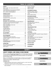
... THE EXPANSION BOARD 31 MAINTENANCE 32 IMPORTANT SAFETY INFORMATION 32 MAINTENANCE CHART 32 BATTERIES 32 DRIVE CHAIN 32 TROUBLESHOOTING 33 ERROR CODES 33 CONTROL BOARD LEDS 36 TROUBLESHOOTING CHART 37 APPENDIX 40 TYPES OF INSTALLATIONS 40 DETERMINE LOCATION FOR CONCRETE PAD AND OPERATOR.........41 ATTACH THE CHAIN 41 SOLAR PANEL(S 42 SAMS WIRING WITH RELAYS NOT ENERGIZED 46 DUAL GATE SETTINGS 46 LIMIT SETUP WITH A REMOTE CONTROL 47 WIRING DIAGRAM 48 REPAIR PARTS 49 ACCESSORIES 51 WARRANTY 53 SAFETY SAFETY SYMBOL AND SIGNAL WORD REVIEW When...
... THE EXPANSION BOARD 31 MAINTENANCE 32 IMPORTANT SAFETY INFORMATION 32 MAINTENANCE CHART 32 BATTERIES 32 DRIVE CHAIN 32 TROUBLESHOOTING 33 ERROR CODES 33 CONTROL BOARD LEDS 36 TROUBLESHOOTING CHART 37 APPENDIX 40 TYPES OF INSTALLATIONS 40 DETERMINE LOCATION FOR CONCRETE PAD AND OPERATOR.........41 ATTACH THE CHAIN 41 SOLAR PANEL(S 42 SAMS WIRING WITH RELAYS NOT ENERGIZED 46 DUAL GATE SETTINGS 46 LIMIT SETUP WITH A REMOTE CONTROL 47 WIRING DIAGRAM 48 REPAIR PARTS 49 ACCESSORIES 51 WARRANTY 53 SAFETY SAFETY SYMBOL AND SIGNAL WORD REVIEW When...

CSL24VDC Installation Manual
Page 4
... security personnel. RESTRICTED ACCESS VEHICULAR GATE OPERATOR IV A vehicular gate operator (or system) intended for use in a guarded industrial location or building such as an airport security area or other locations not accessible by or intended to cover both the opening and closing directions is not moving. • KEEP GATES PROPERLY MAINTAINED. Use of a single device to service the general public. The installer is required to adjust and retest the gate operator...
... security personnel. RESTRICTED ACCESS VEHICULAR GATE OPERATOR IV A vehicular gate operator (or system) intended for use in a guarded industrial location or building such as an airport security area or other locations not accessible by or intended to cover both the opening and closing directions is not moving. • KEEP GATES PROPERLY MAINTAINED. Use of a single device to service the general public. The installer is required to adjust and retest the gate operator...

CSL24VDC Installation Manual
Page 11
... or sticking gate. • If one control (force or travel . • Mount controls at the leading and trailing edges, and post mounted BOTH inside and outside a horizontal swing gate. STEP 1 DETERMINE LOCATION FOR CONCRETE PAD AND OPERATOR Refer to protect anyone who may travel limits) is adjusted, the other control may be installed near the front roller of the gate or near a moving part of the gate. • Install Warning...
... or sticking gate. • If one control (force or travel . • Mount controls at the leading and trailing edges, and post mounted BOTH inside and outside a horizontal swing gate. STEP 1 DETERMINE LOCATION FOR CONCRETE PAD AND OPERATOR Refer to protect anyone who may travel limits) is adjusted, the other control may be installed near the front roller of the gate or near a moving part of the gate. • Install Warning...

CSL24VDC Installation Manual
Page 16
... run the operator without consulting the wiring diagram. Connect the green wire to the chassis. 5. Connect the black wire to service. • Disconnect power at that you install an edge sensor BEFORE proceeding with the screws. The location of SEVERE INJURY or DEATH: • ANY maintenance to the operator or in separate conduits. Replace the outlet housing by removing the screws (2). 2. Replace the junction box cover. NOTE: The operator should be wired for either...
... run the operator without consulting the wiring diagram. Connect the green wire to the chassis. 5. Connect the black wire to service. • Disconnect power at that you install an edge sensor BEFORE proceeding with the screws. The location of SEVERE INJURY or DEATH: • ANY maintenance to the operator or in separate conduits. Replace the outlet housing by removing the screws (2). 2. Replace the junction box cover. NOTE: The operator should be wired for either...

CSL24VDC Installation Manual
Page 24
... OPEN, CLOSE, and STOP Three separate buttons as OPEN, CLOSE, and STOP DESCRIPTION PROGRAMMING STEPS Program a single button on a circuit different from that to be erased before programming any interference received, including interference that may cause harmful interference to program. Press and release the LEARN button (operator will beep and green XMITTER as an open, close the gate. 1. Press and release the LEARN button (operator will beep and green XMITTER as an open only. The operator will automatically exit learn mode (operator will beep and green XMITTER LED...
... OPEN, CLOSE, and STOP Three separate buttons as OPEN, CLOSE, and STOP DESCRIPTION PROGRAMMING STEPS Program a single button on a circuit different from that to be erased before programming any interference received, including interference that may cause harmful interference to program. Press and release the LEARN button (operator will beep and green XMITTER as an open, close the gate. 1. Press and release the LEARN button (operator will beep and green XMITTER as an open only. The operator will automatically exit learn mode (operator will beep and green XMITTER LED...

CSL24VDC Installation Manual
Page 25
... the SET OPEN and SET CLOSE LEDs (exiting learn mode for three minutes. 6. Press and release the LEARN button (operator will beep and green XMITTER LED will need to add devices. OR USING THE RESET BUTTON ON THE OPERATOR 1. Use an internet enabled computer or smartphone to be controlled through the LiftMaster Internet Gateway app. All remote control codes are now erased. The gate operator can then be set. Press and release both the SET OPEN and SET CLOSE LEDs blink rapidly and the operator beeps. 2.
... the SET OPEN and SET CLOSE LEDs (exiting learn mode for three minutes. 6. Press and release the LEARN button (operator will beep and green XMITTER LED will need to add devices. OR USING THE RESET BUTTON ON THE OPERATOR 1. Use an internet enabled computer or smartphone to be controlled through the LiftMaster Internet Gateway app. All remote control codes are now erased. The gate operator can then be set. Press and release both the SET OPEN and SET CLOSE LEDs blink rapidly and the operator beeps. 2.
CSL24VDC Installation Manual
Page 27
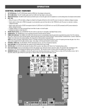
See Status LED Chart in Limit setting mode. See Adjust Limits section. 2 SET CLOSE Button: The SET CLOSE button sets the CLOSE limit. See Bipart Delay section. 6 LEARN Button: The LEARN button is for dual gates. The range is used only for programming remote controls and the network. 7 TIMER-TO-CLOSE dial: The TIMER-TO-CLOSE (TTC) dial can be set to the TTC expiring will either open or close the gate. • Critically low battery is less than 23 V 5 BIPART DELAY Switch: The LOCK/BIPART DELAY...
See Status LED Chart in Limit setting mode. See Adjust Limits section. 2 SET CLOSE Button: The SET CLOSE button sets the CLOSE limit. See Bipart Delay section. 6 LEARN Button: The LEARN button is for dual gates. The range is used only for programming remote controls and the network. 7 TIMER-TO-CLOSE dial: The TIMER-TO-CLOSE (TTC) dial can be set to the TTC expiring will either open or close the gate. • Critically low battery is less than 23 V 5 BIPART DELAY Switch: The LOCK/BIPART DELAY...

CSL24VDC Installation Manual
Page 34
... Signs Manual Disconnect Drive Chain and Sprockets Belt and Pulley Gate Accessories Electrical Chassis Mounting Bolts Operator Batteries Make sure they are no more frequent maintenance checks. • Limits may have no obstructions to gate travel , retest the gate operator. Batteries do not perform well in place of maintenance the area MUST be cleared and secured, at the fuse box BEFORE proceeding. To tighten the drive chain adjust either of the two chain eye only LiftMaster part 29...
... Signs Manual Disconnect Drive Chain and Sprockets Belt and Pulley Gate Accessories Electrical Chassis Mounting Bolts Operator Batteries Make sure they are no more frequent maintenance checks. • Limits may have no obstructions to gate travel , retest the gate operator. Batteries do not perform well in place of maintenance the area MUST be cleared and secured, at the fuse box BEFORE proceeding. To tighten the drive chain adjust either of the two chain eye only LiftMaster part 29...
CSL24VDC Installation Manual
Page 35
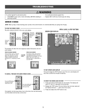
... OPEN button until "Er" shows OPEN, CLOSE, & STOP BUTTONS ERROR CODE DISPLAY COM LINK BA The operator will show the error sequence number followed by the error code number: ERROR SEQUENCE NUMBER The first number shown is the most recent errors ("01"). The error history has now been reset and the display will show "- -" until a new error occurs. 3. ERROR CODE NUMBER The second number shown after two minutes of errors that you unplug the J15 plug. Press and release the STOP button...
... OPEN button until "Er" shows OPEN, CLOSE, & STOP BUTTONS ERROR CODE DISPLAY COM LINK BA The operator will show the error sequence number followed by the error code number: ERROR SEQUENCE NUMBER The first number shown is the most recent errors ("01"). The error history has now been reset and the display will show "- -" until a new error occurs. 3. ERROR CODE NUMBER The second number shown after two minutes of errors that you unplug the J15 plug. Press and release the STOP button...

CSL24VDC Installation Manual
Page 36
... encoder Check the operator cable connections, then reprogram the limits. Hard Stop Limit Limit may be set limits. Battery overcurrent Possible short of monitored entrapment protection devices (one) not installed. Review power supply and wiring. If issue continues, replace control board. If so, erase limits, enter limit setup mode and set too tightly against a non-resilient hard stop (re-adjust limit). Replace batteries if depleted to force a fresh boot. May be a short in Loop Detector only) Check loop wiring throughout connection. CLOSE EYE/INTERRUPT held...
... encoder Check the operator cable connections, then reprogram the limits. Hard Stop Limit Limit may be set limits. Battery overcurrent Possible short of monitored entrapment protection devices (one) not installed. Review power supply and wiring. If issue continues, replace control board. If so, erase limits, enter limit setup mode and set too tightly against a non-resilient hard stop (re-adjust limit). Replace batteries if depleted to force a fresh boot. May be a short in Loop Detector only) Check loop wiring throughout connection. CLOSE EYE/INTERRUPT held...

CSL24VDC Installation Manual
Page 39
... closed circuit, or put a jumper on batteries and battery voltage must be 23.0 Vdc or higher. Re-learn wireless control/transmitter to a wireless control or transmitter a) Check XMITTER LED when wireless control is active b) Stop button is active c) Reset button is stuck a) Activate wireless control and check XMITTER LED is not "stuck on " detector g) Defective control board g) Replace defective control board Gate moves, but cannot set correct limits. Replace wireless control as needed . Check other wireless controls or devices. c) Low battery voltage a) Check all Open and Close...
... closed circuit, or put a jumper on batteries and battery voltage must be 23.0 Vdc or higher. Re-learn wireless control/transmitter to a wireless control or transmitter a) Check XMITTER LED when wireless control is active b) Stop button is active c) Reset button is stuck a) Activate wireless control and check XMITTER LED is not "stuck on " detector g) Defective control board g) Replace defective control board Gate moves, but cannot set correct limits. Replace wireless control as needed . Check other wireless controls or devices. c) Low battery voltage a) Check all Open and Close...

CSL24VDC Installation Manual
Page 40
... stop , and may reverse direction. If no AC power, then running . b) Replace defective Shadow loop detector. a) Check photoelectric sensor wiring. b) Replace defective photoelectric sensor. b) Replace defective edge sensor. Press the reset button to all inputs on expansion board. Alarm beeps when running on batteries and battery voltage must be 23.0 Vdc or higher. a) Incorrect Bipart switch setting a) Expansion board setting b) Constant pressure to ON Shadow loop does not keep gate at open or close is given a) Change setting...
... stop , and may reverse direction. If no AC power, then running . b) Replace defective Shadow loop detector. a) Check photoelectric sensor wiring. b) Replace defective photoelectric sensor. b) Replace defective edge sensor. Press the reset button to all inputs on expansion board. Alarm beeps when running on batteries and battery voltage must be 23.0 Vdc or higher. a) Incorrect Bipart switch setting a) Expansion board setting b) Constant pressure to ON Shadow loop does not keep gate at open or close is given a) Change setting...

CSL24VDC Installation Manual
Page 48
... Dipswitch settings for AUX Relay 1: 1-OFF, 2-OFF, 3-ON AUX Relay 1 DUAL GATE SETTINGS NOTE: We recommend that all accessories and board configurations are set on the primary operator. SECONDARY OPERATOR Program remote controls 51 to 100 to primary Monitor operator. Garage and Gate Program to the secondary operator FEATURE PRIMARY OPERATOR QUICK CLOSE Switch ANTI-TAIL Switch LOW BATT Switch AC FAIL OPEN/BATT Switch ON ON Battery Fail OPEN: OPEN Battery Fail CLOSE: CLOSE OPEN SECONDARY OPERATOR OFF OFF Battery Fail OPEN: OPEN Battery Fail CLOSE: CLOSE OPEN...
... Dipswitch settings for AUX Relay 1: 1-OFF, 2-OFF, 3-ON AUX Relay 1 DUAL GATE SETTINGS NOTE: We recommend that all accessories and board configurations are set on the primary operator. SECONDARY OPERATOR Program remote controls 51 to 100 to primary Monitor operator. Garage and Gate Program to the secondary operator FEATURE PRIMARY OPERATOR QUICK CLOSE Switch ANTI-TAIL Switch LOW BATT Switch AC FAIL OPEN/BATT Switch ON ON Battery Fail OPEN: OPEN Battery Fail CLOSE: CLOSE OPEN SECONDARY OPERATOR OFF OFF Battery Fail OPEN: OPEN Battery Fail CLOSE: CLOSE OPEN...
CSL24VDC Installation Manual
Page 53
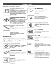
... power loop detectors mounted and wired separately inside control box. Model 65ME120C5 REMOTE CONTROLS LiftMaster offers a variety of the electronic beam and stop the operator. Model CP3 3-BUTTON MINI-REMOTE CONTROL The 3-button remote control can be connected to operate gate operator from outside by LiftMaster after 1993. The following remote controls are compatible with operators manufactured by entering a 4-digit code on a specially designed keypad. Model LD7LP VEHICLE SENSING PROBE The vehicle sensing probe is to replace or add a solar panel to 4-button, visor or key chain...
... power loop detectors mounted and wired separately inside control box. Model 65ME120C5 REMOTE CONTROLS LiftMaster offers a variety of the electronic beam and stop the operator. Model CP3 3-BUTTON MINI-REMOTE CONTROL The 3-button remote control can be connected to operate gate operator from outside by LiftMaster after 1993. The following remote controls are compatible with operators manufactured by entering a 4-digit code on a specially designed keypad. Model LD7LP VEHICLE SENSING PROBE The vehicle sensing probe is to replace or add a solar panel to 4-button, visor or key chain...
CSL24VDC Installation Manual
Page 55
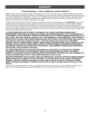
... NOT COVER NON-DEFECT DAMAGE, DAMAGE CAUSED BY IMPROPER INSTALLATION, OPERATION OR CARE (INCLUDING, BUT NOT LIMITED TO ABUSE, MISUSE, FAILURE TO PROVIDE REASONABLE AND NECESSARY MAINTENANCE, UNAUTHORIZED REPAIRS OR ANY ALTERATIONS TO THIS PRODUCT), LABOR CHARGES FOR REINSTALLING A REPAIRED OR REPLACED UNIT, OR REPLACEMENT OF BATTERIES. This limited warranty gives you specific legal rights, and you . ANY SERVICE CALL THAT DETERMINES THE PROBLEM HAS...
... NOT COVER NON-DEFECT DAMAGE, DAMAGE CAUSED BY IMPROPER INSTALLATION, OPERATION OR CARE (INCLUDING, BUT NOT LIMITED TO ABUSE, MISUSE, FAILURE TO PROVIDE REASONABLE AND NECESSARY MAINTENANCE, UNAUTHORIZED REPAIRS OR ANY ALTERATIONS TO THIS PRODUCT), LABOR CHARGES FOR REINSTALLING A REPAIRED OR REPLACED UNIT, OR REPLACEMENT OF BATTERIES. This limited warranty gives you specific legal rights, and you . ANY SERVICE CALL THAT DETERMINES THE PROBLEM HAS...

CSL24VDC Gate Operator and Accessory Site Plan Manual
Page 1
... be limited by letting them monitor, open . Customer: Project: Architect/Engineer: Contractor: Gate Length (ft.): Power Source (120 or 240 VAC): ORDER SUMMARY Gate Weight (lbs.): Date: Solar (Y/N): LiftMaster.com 1 828LM* Internet Gateway Imagine your Customer's router and enables smartphone control, does this operator. Works in Loop Detector, (LOOPDETLM) innovative design includes 8 sensitivity settings & boost, ensures vehicles are ideal for Post Mounting For post mounting model CSL24VDC commercial slide operator...
... be limited by letting them monitor, open . Customer: Project: Architect/Engineer: Contractor: Gate Length (ft.): Power Source (120 or 240 VAC): ORDER SUMMARY Gate Weight (lbs.): Date: Solar (Y/N): LiftMaster.com 1 828LM* Internet Gateway Imagine your Customer's router and enables smartphone control, does this operator. Works in Loop Detector, (LOOPDETLM) innovative design includes 8 sensitivity settings & boost, ensures vehicles are ideal for Post Mounting For post mounting model CSL24VDC commercial slide operator...

CSL24VDC Gate Operator and Accessory Site Plan Manual
Page 2
... frost line. CONDUIT LOCATION (Gate) 7" 1-1/4" 3-1/2" min. 1-2" 2-3/4" MOUNTING FOOTPRINT 11.9" 10.3" 2.85" (Conduit) .63" 13" 23" 26" 10.4" 14.1" 8" 26" (66 cm) 4-1/2" 15" (Pad) 24" 14.6" SAFETY LAYOUT Sensors for wireless dual gate communication. Warning Sign Safety Catch Roller Edge Sensor Edge Sensor Photoelectric Sensors Earth Ground Rod Check national and local codes for Close Cycle SINGLE GATE Warning Sign Wire Gauge 14 12 10 8 6 4 OPERATOR POWER SOURCE 120 Vac...
... frost line. CONDUIT LOCATION (Gate) 7" 1-1/4" 3-1/2" min. 1-2" 2-3/4" MOUNTING FOOTPRINT 11.9" 10.3" 2.85" (Conduit) .63" 13" 23" 26" 10.4" 14.1" 8" 26" (66 cm) 4-1/2" 15" (Pad) 24" 14.6" SAFETY LAYOUT Sensors for wireless dual gate communication. Warning Sign Safety Catch Roller Edge Sensor Edge Sensor Photoelectric Sensors Earth Ground Rod Check national and local codes for Close Cycle SINGLE GATE Warning Sign Wire Gauge 14 12 10 8 6 4 OPERATOR POWER SOURCE 120 Vac...


