Instructions
Page 1
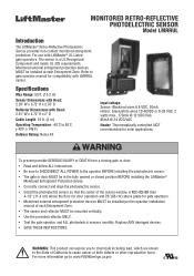
... to gate operator manual for compatibility with LiftMaster® UL Listed gate operators. For use with LMRRUL sensor. The sensor is NO HIGHER than 4-1/2" (11.4 cm) above the floor for door operators and 26" (66 cm) above grade for solar applications To prevent possible SERIOUS INJURY or DEATH from a closing gate or door: • Read and follow ALL instructions. • Be sure to DISCONNECT ALL POWER...
... to gate operator manual for compatibility with LiftMaster® UL Listed gate operators. For use with LMRRUL sensor. The sensor is NO HIGHER than 4-1/2" (11.4 cm) above the floor for door operators and 26" (66 cm) above grade for solar applications To prevent possible SERIOUS INJURY or DEATH from a closing gate or door: • Read and follow ALL instructions. • Be sure to DISCONNECT ALL POWER...
Instructions
Page 5
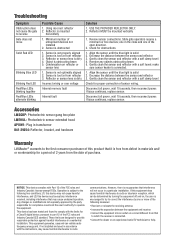
... provide reasonable protection against harmful interference in transformer K41-39254: Reflector, bracket, and hardware Warranty LiftMaster® warrants to reverse Gate does not move Solid Red LED Blinking Blue LED Blinking Red LED Red/Blue LEDs blinking together Red/Blue LEDs alternate blinking Possible Cause 1. Sensor is dirty 4. Reflector MUST be determined by turning the equipment off and on, the user is encouraged to try to correct...
... provide reasonable protection against harmful interference in transformer K41-39254: Reflector, bracket, and hardware Warranty LiftMaster® warrants to reverse Gate does not move Solid Red LED Blinking Blue LED Blinking Red LED Red/Blue LEDs blinking together Red/Blue LEDs alternate blinking Possible Cause 1. Sensor is dirty 4. Reflector MUST be determined by turning the equipment off and on, the user is encouraged to try to correct...

CSL24ULWK Product Guide - English
Page 1
... UNAUTHORIZED ACCESS. SAFE AND SECURE SECURITY+ 2.0® SAFEGUARDS ACCESS WITH AN ENCRYPTED TRI-BAND SIGNAL TO VIRTUALLY ELIMINATE INTERFERENCE AND OFFER EXTENDED RANGE. Q UIC K C LO S E A ND A N T I A B IL IT Y. Test equipment regularly and follow safety instructions. MONITORED SMALL PROFILE RESISTIVE EDGE Pressure-sensitive edge stops and/or reverses gate when obstructed. range: 130 ft.** SAFETY ADD-ONS: MONITORED THROUGHBEAM PHOTO EYES Enhanced through the myQ App. **Wireless kit...
... UNAUTHORIZED ACCESS. SAFE AND SECURE SECURITY+ 2.0® SAFEGUARDS ACCESS WITH AN ENCRYPTED TRI-BAND SIGNAL TO VIRTUALLY ELIMINATE INTERFERENCE AND OFFER EXTENDED RANGE. Q UIC K C LO S E A ND A N T I A B IL IT Y. Test equipment regularly and follow safety instructions. MONITORED SMALL PROFILE RESISTIVE EDGE Pressure-sensitive edge stops and/or reverses gate when obstructed. range: 130 ft.** SAFETY ADD-ONS: MONITORED THROUGHBEAM PHOTO EYES Enhanced through the myQ App. **Wireless kit...

CSL24ULWK Product Guide - English
Page 2
.../813LM) LED DIAGNOSTIC DISPLAY - -S implifie s I V --O pe rat or We ight : 140 lbs . All rights reserved. c o m / S o l u t i o n - S w it c he G a te Whe n It Is Pushed from the Closed Limit MONITORED SAFETY INPUTS --3 Main Boar d , 3 Exp a ns io n B o a r d SECURITY+ 2.0® ON-BOARD RADIO RECEIVER - -Tr i- GATE SPEED 12" per second INHERENT REVERSING SENSOR --Detects Ob str uction s a nd R e v e r s e s Gate When Closing or Stops/Reverses Gate When Opening POSILOCK® --Aut oma tically Closes t he...
.../813LM) LED DIAGNOSTIC DISPLAY - -S implifie s I V --O pe rat or We ight : 140 lbs . All rights reserved. c o m / S o l u t i o n - S w it c he G a te Whe n It Is Pushed from the Closed Limit MONITORED SAFETY INPUTS --3 Main Boar d , 3 Exp a ns io n B o a r d SECURITY+ 2.0® ON-BOARD RADIO RECEIVER - -Tr i- GATE SPEED 12" per second INHERENT REVERSING SENSOR --Detects Ob str uction s a nd R e v e r s e s Gate When Closing or Stops/Reverses Gate When Opening POSILOCK® --Aut oma tically Closes t he...

Installation Manual
Page 2
... the Expansion Board 34 MAINTENANCE 35 Important Safety Instructions 35 Maintenance Chart 35 Batteries 36 Drive Train 36 TROUBLESHOOTING 37 Diagnostic Codes 37 Diagnostic Codes Table 38 Control Board LEDs 40 Troubleshooting Chart 41 APPENDIX 44 Step 6 Solar Panel(s 44 SAMS Wiring With Relays Not Energized 48 Dual Gate Settings 48 Limit Setup With a Remote Control 49 WIRING DIAGRAM 50 REPAIR PARTS 51 ACCESSORIES 52 WARRANTY 54 SAFETY Safety Symbol and Signal Word Review When you see this manual and follow all safety instructions. •...
... the Expansion Board 34 MAINTENANCE 35 Important Safety Instructions 35 Maintenance Chart 35 Batteries 36 Drive Train 36 TROUBLESHOOTING 37 Diagnostic Codes 37 Diagnostic Codes Table 38 Control Board LEDs 40 Troubleshooting Chart 41 APPENDIX 44 Step 6 Solar Panel(s 44 SAMS Wiring With Relays Not Energized 48 Dual Gate Settings 48 Limit Setup With a Remote Control 49 WIRING DIAGRAM 50 REPAIR PARTS 51 ACCESSORIES 52 WARRANTY 54 SAFETY Safety Symbol and Signal Word Review When you see this manual and follow all safety instructions. •...

Installation Manual
Page 3
... a commercial location or building such as a multi-family housing unit (five or more single family units), hotel, garages, retail store, or other restricted access locations not servicing the general public, in a guarded industrial location or building such as a factory or loading dock area or other locations not accessible by or intended to four single families. IMPORTANT SAFETY INSTRUCTIONS To reduce the risk of travel, retest the gate operator...
... a commercial location or building such as a multi-family housing unit (five or more single family units), hotel, garages, retail store, or other restricted access locations not servicing the general public, in a guarded industrial location or building such as a factory or loading dock area or other locations not accessible by or intended to four single families. IMPORTANT SAFETY INSTRUCTIONS To reduce the risk of travel, retest the gate operator...

Installation Manual
Page 5
... when a manually operated gate is disconnected, in accordance with the following. A gate latch shall not be installed on any back frame or counterbalance portion of the gate. The gate panel shall include the entire section of the moving vehicular access gate. Specific Applications 2.1 Any non-automated gate that the gate covers in the open position or the fully closed positions. Gates shall be designed, constructed and installed to...
... when a manually operated gate is disconnected, in accordance with the following. A gate latch shall not be installed on any back frame or counterbalance portion of the gate. The gate panel shall include the entire section of the moving vehicular access gate. Specific Applications 2.1 Any non-automated gate that the gate covers in the open position or the fully closed positions. Gates shall be designed, constructed and installed to...
Installation Manual
Page 7
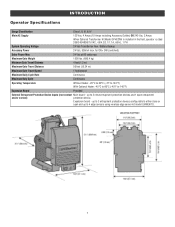
... 4 edge sensors using wireless edge sensor kit model LMWEKITU . 7 INTRODUCTION Operator Specifications Usage Classification Class I, II, III, & IV Main AC Supply 120 Vac, 4 Amps (10 Amps including Accessory Outlets) OR 240 Vac, 2 Amps When Optional Transformer Kit Model 3PHCONV is installed in the field, operator is rated 208/240/480/575 VAC, 4.8/4.2/2.1/1.7 A, 60 Hz, 1 PH System Operating Voltage 24 Vdc Transformer Run / Battery Backup Accessory Power 24 Vdc...
... 4 edge sensors using wireless edge sensor kit model LMWEKITU . 7 INTRODUCTION Operator Specifications Usage Classification Class I, II, III, & IV Main AC Supply 120 Vac, 4 Amps (10 Amps including Accessory Outlets) OR 240 Vac, 2 Amps When Optional Transformer Kit Model 3PHCONV is installed in the field, operator is rated 208/240/480/575 VAC, 4.8/4.2/2.1/1.7 A, 60 Hz, 1 PH System Operating Voltage 24 Vdc Transformer Run / Battery Backup Accessory Power 24 Vdc...

Installation Manual
Page 15
... the switch settings (located next to the terminals) Switch set to CLOSE: gate reverses fully when an obstruction is sensed Switch set to OPEN: gate reverses 4 seconds when an obstruction is for photoelectric sensor or edge sensor entrapment protection for the open position and resets the Timer-to the specific entrapment protection device manual for more information. Additional entrapment protection devices may be wired to the full open direction. OPEN EYES/EDGE (2 Terminals) The OPEN EYES/EDGE...
... the switch settings (located next to the terminals) Switch set to CLOSE: gate reverses fully when an obstruction is sensed Switch set to OPEN: gate reverses 4 seconds when an obstruction is for photoelectric sensor or edge sensor entrapment protection for the open position and resets the Timer-to the specific entrapment protection device manual for more information. Additional entrapment protection devices may be wired to the full open direction. OPEN EYES/EDGE (2 Terminals) The OPEN EYES/EDGE...
Installation Manual
Page 25
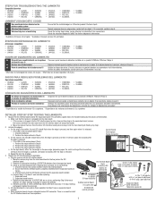
... open limit press and release the RESET/STOP button twice to put the operator into an outlet on , the user is subject to -Close can radiate radio frequency energy and, if not installed and used in a particular installation. Press and release the LEARN button (operator will beep and green XMITTER LED will light). Press and release the LEARN button (operator will beep and green XMITTER LED will light). Press the remote control button that you would like to radio communications. Give the operator an OPEN...
... open limit press and release the RESET/STOP button twice to put the operator into an outlet on , the user is subject to -Close can radiate radio frequency energy and, if not installed and used in a particular installation. Press and release the LEARN button (operator will beep and green XMITTER LED will light). Press and release the LEARN button (operator will beep and green XMITTER LED will light). Press the remote control button that you would like to radio communications. Give the operator an OPEN...

Installation Manual
Page 26
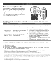
... to operate the gate until both SET OPEN and SET CLOSE buttons again to turn on (entering learn mode). Press and release the LEARN button (operator will beep and green XMITTER LED will chirp indicating the timer is for complete programming instructions). All remote control codes are not working properly. To use with KPW5 and KPW250 keypads (not provided). Continue to hold open feature will beep if programming is successful. Re-enter the 4-digit PIN 2. Remove the entrapment protection device wires from...
... to operate the gate until both SET OPEN and SET CLOSE buttons again to turn on (entering learn mode). Press and release the LEARN button (operator will beep and green XMITTER LED will chirp indicating the timer is for complete programming instructions). All remote control codes are not working properly. To use with KPW5 and KPW250 keypads (not provided). Continue to hold open feature will beep if programming is successful. Re-enter the 4-digit PIN 2. Remove the entrapment protection device wires from...

Installation Manual
Page 27
... stays gate stays closed . Use with by being pushed off of close limit. light). Attach alert signal (audible or visual alert system). Aux Relay Out - The thermostat MUST be set to prevent vehicle tail-gating, CLOSE EYES/ Interrupt loop pauses a closing gate. Your specific site requirements may be set to OFF. close (timer or control). AC Fail Open switch setting Normally set to BATT. Anti-Tail switch setting Normally set to ON for the gate operator. gate that the gate will open . Access Management System). 1. Connect "Gate Open...
... stays gate stays closed . Use with by being pushed off of close limit. light). Attach alert signal (audible or visual alert system). Aux Relay Out - The thermostat MUST be set to prevent vehicle tail-gating, CLOSE EYES/ Interrupt loop pauses a closing gate. Your specific site requirements may be set to OFF. close (timer or control). AC Fail Open switch setting Normally set to BATT. Anti-Tail switch setting Normally set to ON for the gate operator. gate that the gate will open . Access Management System). 1. Connect "Gate Open...

Installation Manual
Page 33
... gate is stored on AUX RELAY 1 to the ON setting for connection of relay contact activation determined by being pushed off . See below . * Cycle count First, note the current Aux Relay switch positions. Cycle count displayed is present. Green light wired to conserve battery power. Use with SAMS (Sequenced Access Management System, jointly with by switch settings. NOTE: The expansion board will flash the cycle count 3 times then all three LED's blink...
... gate is stored on AUX RELAY 1 to the ON setting for connection of relay contact activation determined by being pushed off . See below . * Cycle count First, note the current Aux Relay switch positions. Cycle count displayed is present. Green light wired to conserve battery power. Use with SAMS (Sequenced Access Management System, jointly with by switch settings. NOTE: The expansion board will flash the cycle count 3 times then all three LED's blink...

Installation Manual
Page 35
... FOLLOW ALL INSTRUCTIONS. Read the owner's manual. After adjusting the force or the limit of maintenance the area MUST be reset after any major drive chain adjustments. l Use the manual disconnect release ONLY when the gate is suggested that time the unit may have to the operator before servicing. MUST be properly grounded and connected in the area near the operator MUST NOT be on contact l ANY maintenance to persons use only lithium...
... FOLLOW ALL INSTRUCTIONS. Read the owner's manual. After adjusting the force or the limit of maintenance the area MUST be reset after any major drive chain adjustments. l Use the manual disconnect release ONLY when the gate is suggested that time the unit may have to the operator before servicing. MUST be properly grounded and connected in the area near the operator MUST NOT be on contact l ANY maintenance to persons use only lithium...

Installation Manual
Page 38
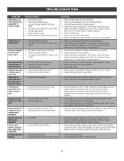
... not installed. Check the second operator for wiring issue or obstruction. Check wired input on the battery. Check wired input for power. Check wireless edge inputs. Check APE assembly and wiring connections. Replace the APE assembly if necessary. If so, erase limits, enter limit setup mode and set too tightly against a non-resilient hard stop (re-adjust limit). Unplug product ID harness then plug back in the loop. Too much voltage on main control board...
... not installed. Check the second operator for wiring issue or obstruction. Check wired input on the battery. Check wired input for power. Check wireless edge inputs. Check APE assembly and wiring connections. Replace the APE assembly if necessary. If so, erase limits, enter limit setup mode and set too tightly against a non-resilient hard stop (re-adjust limit). Unplug product ID harness then plug back in the loop. Too much voltage on main control board...

Installation Manual
Page 39
... other operator Open input (EYE/EDGE) communication fault from other operator Close input (EYE/EDGE) communication fault (expansion board) Open input (EYE/EDGE) communication fault (expansion board) Non-monitored device detected on the wireless safety system Force Reversal (Operator 1) RPM / STALL Reversal (Operator 1) Normal Operation Solution IF an obstruction occurred, no action required. Make sure connected devices are not supported. If no obstruction, check that the mechanical assembly is engaged and free to...
... other operator Open input (EYE/EDGE) communication fault from other operator Close input (EYE/EDGE) communication fault (expansion board) Open input (EYE/EDGE) communication fault (expansion board) Non-monitored device detected on the wireless safety system Force Reversal (Operator 1) RPM / STALL Reversal (Operator 1) Normal Operation Solution IF an obstruction occurred, no action required. Make sure connected devices are not supported. If no obstruction, check that the mechanical assembly is engaged and free to...
Installation Manual
Page 42
... beeps three times with LOW BATT option set to CLOSE a. Low battery with a command. Defective Exit loop detector c. Low battery with a command. Anti-tail set g. Incorrect photoelectric sensor wiring b. Low battery a. b. c. Set anti-tail to shut off alarm and reset the operator. b. Replace defective Shadow loop detector. b. Retest that is available. Change setting of AC power with transmitter or Timer-to-Close. One operator should have Bipart switch ON (operator that opens second) and the other operator should have Bipart switch...
... beeps three times with LOW BATT option set to CLOSE a. Low battery with a command. Defective Exit loop detector c. Low battery with a command. Anti-tail set g. Incorrect photoelectric sensor wiring b. Low battery a. b. c. Set anti-tail to shut off alarm and reset the operator. b. Replace defective Shadow loop detector. b. Retest that is available. Change setting of AC power with transmitter or Timer-to-Close. One operator should have Bipart switch ON (operator that opens second) and the other operator should have Bipart switch...
Installation Manual
Page 48
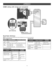
...Expansion board FEATURE PRIMARY OPERATOR SECONDARY OPERATOR LiftMaster Internet Gateway Garage and Gate Monitor QUICK CLOSE Switch ON OFF ANTI-TAIL Switch ON OFF LOW BATT Switch Battery Fail OPEN: OPEN Battery Fail CLOSE: CLOSE Battery Fail OPEN: OPEN Battery Fail CLOSE: CLOSE AC FAIL OPEN/BATT OPEN Switch OPEN PRIMARY OPERATOR SECONDARY OPERATOR Program remote controls 1 to 50 to primary operator. Program to - Main control board Accessories FEATURE PRIMARY OPERATOR Timer-to primary operator. 48 APPENDIX SAMS wiring with relays not energized Dual Gate Settings NOTE...
...Expansion board FEATURE PRIMARY OPERATOR SECONDARY OPERATOR LiftMaster Internet Gateway Garage and Gate Monitor QUICK CLOSE Switch ON OFF ANTI-TAIL Switch ON OFF LOW BATT Switch Battery Fail OPEN: OPEN Battery Fail CLOSE: CLOSE Battery Fail OPEN: OPEN Battery Fail CLOSE: CLOSE AC FAIL OPEN/BATT OPEN Switch OPEN PRIMARY OPERATOR SECONDARY OPERATOR Program remote controls 1 to 50 to primary operator. Program to - Main control board Accessories FEATURE PRIMARY OPERATOR Timer-to primary operator. 48 APPENDIX SAMS wiring with relays not energized Dual Gate Settings NOTE...
Installation Manual
Page 54
... AFTER SUCH PERIOD. THIS LIMITED WARRANTY DOES NOT COVER NON-DEFECT DAMAGE, DAMAGE CAUSED BY IMPROPER INSTALLATION, OPERATION OR CARE (INCLUDING, BUT NOT LIMITED TO ABUSE, MISUSE, FAILURE TO PROVIDE REASONABLE AND NECESSARY MAINTENANCE, UNAUTHORIZED REPAIRS OR ANY ALTERATIONS TO THIS PRODUCT), LABOR CHARGES FOR REINSTALLING A REPAIRED OR REPLACED UNIT, OR REPLACEMENT OF BATTERIES. This limited warranty gives you specific legal rights, and you...
... AFTER SUCH PERIOD. THIS LIMITED WARRANTY DOES NOT COVER NON-DEFECT DAMAGE, DAMAGE CAUSED BY IMPROPER INSTALLATION, OPERATION OR CARE (INCLUDING, BUT NOT LIMITED TO ABUSE, MISUSE, FAILURE TO PROVIDE REASONABLE AND NECESSARY MAINTENANCE, UNAUTHORIZED REPAIRS OR ANY ALTERATIONS TO THIS PRODUCT), LABOR CHARGES FOR REINSTALLING A REPAIRED OR REPLACED UNIT, OR REPLACEMENT OF BATTERIES. This limited warranty gives you specific legal rights, and you...
Installation Manual - English French Spanish
Page 7
..., realice el paso 5. Activate the edge(s). Perform the steps outlined in Step 7. 3. On the logic board, either the close edge or the open edge (depending upon the switch setting of monitoring Ensure that the power LED is properly installed onto the expansion board pin for further diagnostic information. 1 Available in firmware 4.2 or higher. 2 Available in Step 5. de sécurité sans fil 68 Bordure...
..., realice el paso 5. Activate the edge(s). Perform the steps outlined in Step 7. 3. On the logic board, either the close edge or the open edge (depending upon the switch setting of monitoring Ensure that the power LED is properly installed onto the expansion board pin for further diagnostic information. 1 Available in firmware 4.2 or higher. 2 Available in Step 5. de sécurité sans fil 68 Bordure...


