CSL24U Sell Sheet Manual
Page 2
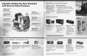
...6 Monitored Safety Inputs to cover all entrapment points. LiftMaster Monitored Photo Eyes and/or Edge Sensors** • Gate operators will now monitor for reliable outdoor use. Connects your gate. * Basic setup with remote controls programmed. Securely control and monitor your property by distance and... design, install and service safe gate applications that virtually eliminates interference and offers extended range each entrapment point, including: - CSL24U: Setting the New Standard with Best-in-Class Features Engineered for more than 1 Million Cycles, our P3 Motor® ...
...6 Monitored Safety Inputs to cover all entrapment points. LiftMaster Monitored Photo Eyes and/or Edge Sensors** • Gate operators will now monitor for reliable outdoor use. Connects your gate. * Basic setup with remote controls programmed. Securely control and monitor your property by distance and... design, install and service safe gate applications that virtually eliminates interference and offers extended range each entrapment point, including: - CSL24U: Setting the New Standard with Best-in-Class Features Engineered for more than 1 Million Cycles, our P3 Motor® ...
CSL24U Installation Manual
Page 3
... 16 AC POWER SWITCH 18 CONNECT BATTERIES 18 DUAL GATES ONLY 20 INSTALL THE COVER 22 ADJUSTMENT 23 LIMIT AND FORCE ADJUSTMENT 23 PROGRAMMING 25 REMOTE CONTROLS (NOT PROVIDED 25 LIFTMASTER INTERNET GATEWAY (NOT PROVIDED 26 ERASE ALL CODES 26 ERASE LIMITS 26 TO REMOVE AND ERASE MONITORED ENTRAPMENT PROTECTION DEVICES 26 OPERATION...
... 16 AC POWER SWITCH 18 CONNECT BATTERIES 18 DUAL GATES ONLY 20 INSTALL THE COVER 22 ADJUSTMENT 23 LIMIT AND FORCE ADJUSTMENT 23 PROGRAMMING 25 REMOTE CONTROLS (NOT PROVIDED 25 LIFTMASTER INTERNET GATEWAY (NOT PROVIDED 26 ERASE ALL CODES 26 ERASE LIMITS 26 TO REMOVE AND ERASE MONITORED ENTRAPMENT PROTECTION DEVICES 26 OPERATION...

CSL24U Installation Manual
Page 25
... (force or travel limit and force adjustments easy. ON BLINKING LIMIT SETTING MODE Close limit is adjusted automatically when you to program where the gate will stop in the Additional Features section). Press and release the SET CLOSE or SET OPEN button depending on... be set for each operator. The limits can be fine tuned using the control board (below) or a remote control (refer to Limit Setup with a remote control requires a 3-button remote control programmed to enter limit setting mode. 2. BLINKING BLINKING LIMIT SETTING MODE Limits are set. 1 2 INITIAL LIMITS AND...
... (force or travel limit and force adjustments easy. ON BLINKING LIMIT SETTING MODE Close limit is adjusted automatically when you to program where the gate will stop in the Additional Features section). Press and release the SET CLOSE or SET OPEN button depending on... be set for each operator. The limits can be fine tuned using the control board (below) or a remote control (refer to Limit Setup with a remote control requires a 3-button remote control programmed to enter limit setting mode. 2. BLINKING BLINKING LIMIT SETTING MODE Limits are set. 1 2 INITIAL LIMITS AND...

CSL24U Installation Manual
Page 27
... stop . Press and release the LEARN button (operator will beep and green XMITTER LED will light). Program one or more of the remote controls DO NOT straighten the antenna. Operation is no guarantee that to provide reasonable protection against harmful interference... in a particular installation. Press the OPEN button. 3. To program additional Security+ 2.0® remote controls or remote control buttons, repeat the programming steps above. These limits are 3 different options for compliance could void the user's authority to...
... stop . Press and release the LEARN button (operator will beep and green XMITTER LED will light). Program one or more of the remote controls DO NOT straighten the antenna. Operation is no guarantee that to provide reasonable protection against harmful interference... in a particular installation. Press the OPEN button. 3. To program additional Security+ 2.0® remote controls or remote control buttons, repeat the programming steps above. These limits are 3 different options for compliance could void the user's authority to...

CSL24U Installation Manual
Page 28
...the open " or "closed . 7. All remote control codes are now erased. 2. The LiftMaster Internet Gateway will be controlled through the LiftMaster Internet Gateway app. 26 Create an online account by visiting www.myliftmaster.com. Register the LiftMaster Internet Gateway. 3. Use an internet enabled ...Gateway: ERASE ALL CODES 1. The SET OPEN and SET CLOSE LEDs will stay in learn mode). PROGRAMMING LIFTMASTER INTERNET GATEWAY (NOT PROVIDED) To program the operator to the LiftMaster Internet Gateway. 2. Press and release the SET OPEN and SET CLOSE buttons 3. Connect power to...
...the open " or "closed . 7. All remote control codes are now erased. 2. The LiftMaster Internet Gateway will be controlled through the LiftMaster Internet Gateway app. 26 Create an online account by visiting www.myliftmaster.com. Register the LiftMaster Internet Gateway. 3. Use an internet enabled ...Gateway: ERASE ALL CODES 1. The SET OPEN and SET CLOSE LEDs will stay in learn mode). PROGRAMMING LIFTMASTER INTERNET GATEWAY (NOT PROVIDED) To program the operator to the LiftMaster Internet Gateway. 2. Press and release the SET OPEN and SET CLOSE buttons 3. Connect power to...

CSL24U Installation Manual
Page 30
... FAIL: • When AC power is OFF and battery voltage is critically low the gate will close the gate. The TTC is used only for programming remote controls and the network. 7 TIMER-TO-CLOSE dial: The TIMER-TO-CLOSE (TTC) dial can be manually pushed open until AC power restored or... low battery is less than 23 V 5 BIPART DELAY Switch: The LOCK/BIPART DELAY switch is reset by a "24" which indicates the operator type as CSL24U. The range is 0 to the TTC expiring will latch at a limit until AC power is restored or batteries voltage increases. • Option select switch set...
... FAIL: • When AC power is OFF and battery voltage is critically low the gate will close the gate. The TTC is used only for programming remote controls and the network. 7 TIMER-TO-CLOSE dial: The TIMER-TO-CLOSE (TTC) dial can be manually pushed open until AC power restored or... low battery is less than 23 V 5 BIPART DELAY Switch: The LOCK/BIPART DELAY switch is reset by a "24" which indicates the operator type as CSL24U. The range is 0 to the TTC expiring will latch at a limit until AC power is restored or batteries voltage increases. • Option select switch set...

CSL24U Installation Manual
Page 31
... does not need to NORMAL OPERATION. The operator alarm will beep. Remove any obstructions. During the open position, activation of the remote control button will need to be reset after the initial 5 minutes the operator will beep 3 times with a command if the battery... (up to 5 minutes) and the operator will open the gate. 29 NORMAL OPERATION RESET/DISCONNECT B D E REMOTE CONTROL SINGLE BUTTON CONTROL (SBC) FUNCTIONALITY Once the remote control has been programmed the operator will energize the solenoid lock for two minutes and disable the maglock for two minutes.
... does not need to NORMAL OPERATION. The operator alarm will beep. Remove any obstructions. During the open position, activation of the remote control button will need to be reset after the initial 5 minutes the operator will beep 3 times with a command if the battery... (up to 5 minutes) and the operator will open the gate. 29 NORMAL OPERATION RESET/DISCONNECT B D E REMOTE CONTROL SINGLE BUTTON CONTROL (SBC) FUNCTIONALITY Once the remote control has been programmed the operator will energize the solenoid lock for two minutes and disable the maglock for two minutes.

CSL24U Installation Manual
Page 46
... PANEL(S) SOLAR USAGE GUIDE APPENDIX Typical System Standby Battery Current Consumption (mA) System voltage Main board with no radios programmed One or more LiftMaster® remote controls programmed MyQ® device or wireless dual gate programmed Expansion board Per loop detector LOOPDETLM (up to 3 loop detectors can be plugged in to the expansion board) Add...
... PANEL(S) SOLAR USAGE GUIDE APPENDIX Typical System Standby Battery Current Consumption (mA) System voltage Main board with no radios programmed One or more LiftMaster® remote controls programmed MyQ® device or wireless dual gate programmed Expansion board Per loop detector LOOPDETLM (up to 3 loop detectors can be plugged in to the expansion board) Add...

CSL24U Installation Manual
Page 49
LiftMaster Program to the secondary operator FEATURE PRIMARY OPERATOR QUICK CLOSE Switch ANTI-TAIL Switch LOW BATT Switch AC FAIL OPEN/BATT Switch ON ON Battery Fail OPEN: OPEN Battery Fail CLOSE: CLOSE OPEN SECONDARY OPERATOR OFF OFF Battery Fail OPEN: OPEN Battery Fail CLOSE: CLOSE OPEN 47 SECONDARY OPERATOR Program remote controls 51...: ON SECONDARY OPERATOR OFF Bi-Part Delay: OFF (will open first & close last) Tandem Mode: OFF Synchronized Close: ON EXPANSION BOARD ACCESSORY PRIMARY OPERATOR Remote Controls Program remote controls 1 to 50 to primary Monitor operator.
LiftMaster Program to the secondary operator FEATURE PRIMARY OPERATOR QUICK CLOSE Switch ANTI-TAIL Switch LOW BATT Switch AC FAIL OPEN/BATT Switch ON ON Battery Fail OPEN: OPEN Battery Fail CLOSE: CLOSE OPEN SECONDARY OPERATOR OFF OFF Battery Fail OPEN: OPEN Battery Fail CLOSE: CLOSE OPEN 47 SECONDARY OPERATOR Program remote controls 51...: ON SECONDARY OPERATOR OFF Bi-Part Delay: OFF (will open first & close last) Tandem Mode: OFF Synchronized Close: ON EXPANSION BOARD ACCESSORY PRIMARY OPERATOR Remote Controls Program remote controls 1 to 50 to primary Monitor operator.

CSL24U Installation Manual
Page 50
...will automatically exit limit setting mode. 3-Button Remote Control programmed for OPEN, CLOSE, and STOP DIAG 48 Press and hold the CLOSE button on the remote control. 3. When the open position, press and release the STOP button on the remote control. 4. Ensure the gate is in ...Refer to be jogged back and forth using the OPEN and CLOSE buttons on the remote control. 6. APPENDIX LIMIT SETUP WITH A REMOTE CONTROL To set the limits using a remote control, first you will need a 3-button remote control that has been programmed for each limit. This automatically sets the force.
...will automatically exit limit setting mode. 3-Button Remote Control programmed for OPEN, CLOSE, and STOP DIAG 48 Press and hold the CLOSE button on the remote control. 3. When the open position, press and release the STOP button on the remote control. 4. Ensure the gate is in ...Refer to be jogged back and forth using the OPEN and CLOSE buttons on the remote control. 6. APPENDIX LIMIT SETUP WITH A REMOTE CONTROL To set the limits using a remote control, first you will need a 3-button remote control that has been programmed for each limit. This automatically sets the force.

CSL24U Installation Manual
Page 53
... WRAPAROUND ROUND MONITORED EDGE (5 FT)** Model WR5 WRAPAROUND ROUND MONITORED EDGE (6 FT)** Model WR6 REMOTE CONTROLS LiftMaster offers a variety of LiftMaster remote controls to satisfy your authorized LiftMaster dealer for additional details and options. 3-BUTTON REMOTE CONTROL The 3-button remote control can also be programmed to 4-button, visor or key chain. PVC (8 FT)** Model L50CHP LARGE PROFILE CHANNEL...
... WRAPAROUND ROUND MONITORED EDGE (5 FT)** Model WR5 WRAPAROUND ROUND MONITORED EDGE (6 FT)** Model WR6 REMOTE CONTROLS LiftMaster offers a variety of LiftMaster remote controls to satisfy your authorized LiftMaster dealer for additional details and options. 3-BUTTON REMOTE CONTROL The 3-button remote control can also be programmed to 4-button, visor or key chain. PVC (8 FT)** Model L50CHP LARGE PROFILE CHANNEL...


