

3950 Addendum Manual
Page 1
... Figure 1 - To order visit www.liftmaster.com or contact door supplier. LIVE OR DEAD SHAFT DOOR IDENTIFICATION LIVE SHAFT DOOR - The axle is important to identify the door type before attempting an installation of the Model 3950 door operator. DEAD SHAFT DOOR - Door Type Identi...fication Dead Shaft Door ADDENDUM DOOR COMPATIBILITY FOR MODEL 3950 IMPORTANT INSTALLATION INSTRUCTIONS It is locked in place while the door opens and ...
... Figure 1 - To order visit www.liftmaster.com or contact door supplier. LIVE OR DEAD SHAFT DOOR IDENTIFICATION LIVE SHAFT DOOR - The axle is important to identify the door type before attempting an installation of the Model 3950 door operator. DEAD SHAFT DOOR - Door Type Identi...fication Dead Shaft Door ADDENDUM DOOR COMPATIBILITY FOR MODEL 3950 IMPORTANT INSTALLATION INSTRUCTIONS It is locked in place while the door opens and ...

3950 Addendum Manual
Page 3
Some door manufacturers require the door to be obstructed by sliding the sprocket on the door shaft to provide an unobstructed platform for Operator), so that the internal door springs do not interfere with the 4.5" mounting pattern on the end of 3". (Figure 6 - Sprocket mounting... SHAFT REQUIREMENTS Dead Shaft Door Construction Drum 2nd Drum Spring Axle Door Bracket Door Guide Figure 4 - Dead Shaft Door Construction Spring Clearance The Model 3950 requires that an extra drum (Figure 4 - 2nd Drum) is added on the end drum (Figure 4 ). Prep for door sprocket mounting. ...
Some door manufacturers require the door to be obstructed by sliding the sprocket on the door shaft to provide an unobstructed platform for Operator), so that the internal door springs do not interfere with the 4.5" mounting pattern on the end of 3". (Figure 6 - Sprocket mounting... SHAFT REQUIREMENTS Dead Shaft Door Construction Drum 2nd Drum Spring Axle Door Bracket Door Guide Figure 4 - Dead Shaft Door Construction Spring Clearance The Model 3950 requires that an extra drum (Figure 4 - 2nd Drum) is added on the end drum (Figure 4 ). Prep for door sprocket mounting. ...

3950 Addendum Manual
Page 5
For a standard wall mount to the outside of the door opening, a minimum of side room depends on which the Model 3950 is required for the desired operator mounting position. 5 Dead Shaft Door brackets should be moved away from the door assembly to be successful. If bent, the drive chain may ...not align to be mounted must also be bent or damaged in order for the Model 3950. Minimum Side Room The ...
For a standard wall mount to the outside of the door opening, a minimum of side room depends on which the Model 3950 is required for the desired operator mounting position. 5 Dead Shaft Door brackets should be moved away from the door assembly to be successful. If bent, the drive chain may ...not align to be mounted must also be bent or damaged in order for the Model 3950. Minimum Side Room The ...

3950 Addendum Manual
Page 6
Figure 7 Operator Drive Options Outside Mount Alignments OUTSIDE MOUNT ALIGNMENTS Sprocket inner position 1" Sprocket middle position 5/8" Inside Mount Alignments INSIDE MOUNT ALIGNMENTS Sprocket inner position 1" Sprocket middle position 1-3/8" Sprocket outer position 1-5/8" 6 OPERATOR DRIVE OPTIONS WHEN USING MODEL 3950MB MOUNTING BRACKET The operator drive sprocket can be attached in one of three positions when inside mounted or one of two positions if outside mounted that provide offset from the outer edge of the door guides: Refer to table below (Figure 7) for details.
Figure 7 Operator Drive Options Outside Mount Alignments OUTSIDE MOUNT ALIGNMENTS Sprocket inner position 1" Sprocket middle position 5/8" Inside Mount Alignments INSIDE MOUNT ALIGNMENTS Sprocket inner position 1" Sprocket middle position 1-3/8" Sprocket outer position 1-5/8" 6 OPERATOR DRIVE OPTIONS WHEN USING MODEL 3950MB MOUNTING BRACKET The operator drive sprocket can be attached in one of three positions when inside mounted or one of two positions if outside mounted that provide offset from the outer edge of the door guides: Refer to table below (Figure 7) for details.

3950 Manual
Page 1
® DOOR OPERATOR Model 3950 For Light Duty Commercial Use The Chamberlain Group, Inc. 845 Larch Avenue Elmhurst, Illinois 60126-1196 www.liftmaster.com Com patible with Owner's Manual ■ Please read this manual and the enclosed safety materials carefully! ■ The door WILL NOT CLOSE unless The ...
® DOOR OPERATOR Model 3950 For Light Duty Commercial Use The Chamberlain Group, Inc. 845 Larch Avenue Elmhurst, Illinois 60126-1196 www.liftmaster.com Com patible with Owner's Manual ■ Please read this manual and the enclosed safety materials carefully! ■ The door WILL NOT CLOSE unless The ...

3950 Manual
Page 2
... 4 Assembly 5 Attach the drive sprocket 5 Attach mounting brackets 5 Installation 6-12 Installation safety instructions 6 Install the door sprocket 6 Mount the operator 7 Attach the emergency release rope and handle 8 Install the single button control station 8 Electrical requirements 9 Install The Protector System 10-12 Adjustment...of serious injury or death if you do not comply with the warnings that accompany it will alert you to your operator 16 Having a problem? (Troubleshooting 17 Diagnostic chart 18 Programming 19-20 To add or reprogram a hand-held remote...
... 4 Assembly 5 Attach the drive sprocket 5 Attach mounting brackets 5 Installation 6-12 Installation safety instructions 6 Install the door sprocket 6 Mount the operator 7 Attach the emergency release rope and handle 8 Install the single button control station 8 Electrical requirements 9 Install The Protector System 10-12 Adjustment...of serious injury or death if you do not comply with the warnings that accompany it will alert you to your operator 16 Having a problem? (Troubleshooting 17 Diagnostic chart 18 Programming 19-20 To add or reprogram a hand-held remote...

3950 Manual
Page 3
... out of which are under EXTREME tension. • Disable ALL locks and remove ALL ropes connected to door BEFORE installing and operating door operator to ensure the door does not bind or stick and is locked. • Chain guard to be installed to the door manufacturer... for more information. To prevent damage to door and operator: • ALWAYS disable locks BEFORE installing and operating the operator. • ONLY operate door operator at 120V, 60 Hz to avoid malfunction and damage. • DO NOT exceed 10 complete cycles of...
... out of which are under EXTREME tension. • Disable ALL locks and remove ALL ropes connected to door BEFORE installing and operating door operator to ensure the door does not bind or stick and is locked. • Chain guard to be installed to the door manufacturer... for more information. To prevent damage to door and operator: • ALWAYS disable locks BEFORE installing and operating the operator. • ONLY operate door operator at 120V, 60 Hz to avoid malfunction and damage. • DO NOT exceed 10 complete cycles of...

3950 Manual
Page 4
... and the parts illustrated below. Note that accessories will depend on the model purchased. Carton Inventory Your door operator is missing, carefully check the packing material. 2-Conductor Bell Wire White & White/Red Mounting Bracket (4) Operator Door Sprockets Safety Labels and Literature Hardware Inventory Installation Hardware Tubular Spacer 1/2" (6) Tubular Spacer 2" (3) Cap Screw 1/4"-20...
... and the parts illustrated below. Note that accessories will depend on the model purchased. Carton Inventory Your door operator is missing, carefully check the packing material. 2-Conductor Bell Wire White & White/Red Mounting Bracket (4) Operator Door Sprockets Safety Labels and Literature Hardware Inventory Installation Hardware Tubular Spacer 1/2" (6) Tubular Spacer 2" (3) Cap Screw 1/4"-20...

3950 Manual
Page 5
...drive sprocket into the output shaft and the drive sprocket. 4. Figure 1 Output Shaft Drive Sprocket Bolt Bolt ASSEMBLY STEP 2 Attach Mounting Brackets The operator can be mounted to aid in the output shaft. 3. The drive sprocket has three holes to the wall with the door sprocket. 1. Fasten ... the self-threading screws (8) provided. Align the center holes in the drive sprocket with the hole in the alignment of the operator. 2. Position two mounting brackets on your installation. Insert bolts into the output shaft. 2. ASSEMBLY STEP 1 Attach the Drive Sprocket The drive ...
...drive sprocket into the output shaft and the drive sprocket. 4. Figure 1 Output Shaft Drive Sprocket Bolt Bolt ASSEMBLY STEP 2 Attach Mounting Brackets The operator can be mounted to aid in the output shaft. 3. The drive sprocket has three holes to the wall with the door sprocket. 1. Fasten ... the self-threading screws (8) provided. Align the center holes in the drive sprocket with the hole in the alignment of the operator. 2. Position two mounting brackets on your installation. Insert bolts into the output shaft. 2. ASSEMBLY STEP 1 Attach the Drive Sprocket The drive ...

3950 Manual
Page 6
...the drum as shown. NOTE: Drive shaft must extend 1-1/2" beyond the door support bracket. Slide the through the door shaft. 3. Install the operator at minimum height of 5 feet (1.5 m). • away from ALL moving parts. Figure 2 Drum Door Sprocket Flange Nut Door Drum Tubular Spacer...Slide the door sprocket onto the end of installation, test safety reversal system. 12. Place manual release/safety reverse test label in door or operator mechanisms. 8. Figure 1 Door Door Shaft Through Bolt Door Sprocket Nylock Nut Drum Door Bracket Door Sprocket Dead shaft type (Figure 2): 1. ...
...the drum as shown. NOTE: Drive shaft must extend 1-1/2" beyond the door support bracket. Slide the through the door shaft. 3. Install the operator at minimum height of 5 feet (1.5 m). • away from ALL moving parts. Figure 2 Drum Door Sprocket Flange Nut Door Drum Tubular Spacer...Slide the door sprocket onto the end of installation, test safety reversal system. 12. Place manual release/safety reverse test label in door or operator mechanisms. 8. Figure 1 Door Door Shaft Through Bolt Door Sprocket Nylock Nut Drum Door Bracket Door Sprocket Dead shaft type (Figure 2): 1. ...

3950 Manual
Page 7
...ends of the chain using a 5/32" Allen wrench. Live Shaft Chain Mounting Hardware (not provided) Dead Shaft Operator Chain Mounting Hardware (not provided) 7 Operator Anchors must be fastened to approximate mounting position, make sure the drive sprocket is available for masonry construction. NOTE...trained door systems technician if door binds, sticks or is not recommended. 1. Make sure the operator output shaft is taut (not tight). INSTALLATION STEP 2 Mount the Operator The operator can be laterally adjusted by removing the bolt from the drive sprocket. 2. To prevent possible ...
...ends of the chain using a 5/32" Allen wrench. Live Shaft Chain Mounting Hardware (not provided) Dead Shaft Operator Chain Mounting Hardware (not provided) 7 Operator Anchors must be fastened to approximate mounting position, make sure the drive sprocket is available for masonry construction. NOTE...trained door systems technician if door binds, sticks or is not recommended. 1. Make sure the operator output shaft is taut (not tight). INSTALLATION STEP 2 Mount the Operator The operator can be laterally adjusted by removing the bolt from the drive sprocket. 2. To prevent possible ...

3950 Manual
Page 8
... WHT Moving Door Can Cause Serious Injury or Death Keep Clear! Door May Move at any Time Without Prior Warning Do Not Let Children Operate the Door or Play in the Door Area Keep Door in sight until completely closed. NEVER permit anyone to 24 VOLT low voltage wires.... heat seal the cut end with an overhand knot at all Times When Door is clear of children at least 5 feet (1.5 m) above the floor. Operator will not function without the jumper. FASTEN LABEL ADJACENT TO DOOR. Motor Unit Emergency Release Cable Overhand Knot Rope Emergency NOTICE Release Handle Overhand Knot...
... WHT Moving Door Can Cause Serious Injury or Death Keep Clear! Door May Move at any Time Without Prior Warning Do Not Let Children Operate the Door or Play in the Door Area Keep Door in sight until completely closed. NEVER permit anyone to 24 VOLT low voltage wires.... heat seal the cut end with an overhand knot at all Times When Door is clear of children at least 5 feet (1.5 m) above the floor. Operator will not function without the jumper. FASTEN LABEL ADJACENT TO DOOR. Motor Unit Emergency Release Cable Overhand Knot Rope Emergency NOTICE Release Handle Overhand Knot...

3950 Manual
Page 9
To prevent possible SERIOUS INJURY or DEATH from unit. 5. PERMANENT WIRING CONNECTION RIGHT WRONG If permanent wiring is required by your operator has a grounding type plug with ALL local electrical and building codes. • NEVER use an extension cord, 2-wire adapter or... the outlet you have, contact a qualified electrician to establish permanent wiring connection. • Door installation and wiring MUST be in the back of the operator (according to the 7/8" hole. 6. Remove cover screws and set the cover aside. 2. Run wires through the 7/8" hole in compliance with a third...
To prevent possible SERIOUS INJURY or DEATH from unit. 5. PERMANENT WIRING CONNECTION RIGHT WRONG If permanent wiring is required by your operator has a grounding type plug with ALL local electrical and building codes. • NEVER use an extension cord, 2-wire adapter or... the outlet you have, contact a qualified electrician to establish permanent wiring connection. • Door installation and wiring MUST be in the back of the operator (according to the 7/8" hole. 6. Remove cover screws and set the cover aside. 2. Run wires through the 7/8" hole in compliance with a third...

3950 Manual
Page 10
... door from a closing . above the floor. The sending eye (with an amber indicator light) transmits an invisible light beam to the door operator BEFORE installing the safety reversing sensor. Be sure power is closing, the door will move in the down direction. The units must be installed... sensor will detect an obstacle in masonry if repositioning is a required safety device and cannot be connected and aligned correctly before the door operator will stop and reverse to a solid surface such as the sun never shines directly into the receiving eye lens. This required safety device...
... door from a closing . above the floor. The sending eye (with an amber indicator light) transmits an invisible light beam to the door operator BEFORE installing the safety reversing sensor. Be sure power is closing, the door will move in the down direction. The units must be installed... sensor will detect an obstacle in masonry if repositioning is a required safety device and cannot be connected and aligned correctly before the door operator will stop and reverse to a solid surface such as the sun never shines directly into the receiving eye lens. This required safety device...

3950 Manual
Page 11
... Indicator Lens Light Figure 3 FLOOR MOUNT (RIGHT SIDE) IWnsaildle Lens Attach with curved arms facing the door. INSTALLING THE BRACKETS Be sure power to the operator is needed, an extension bracket (see accessories) to elevate sensor brackets so the lenses will face each side of three ways, as shown. Make sure...
... Indicator Lens Light Figure 3 FLOOR MOUNT (RIGHT SIDE) IWnsaildle Lens Attach with curved arms facing the door. INSTALLING THE BRACKETS Be sure power to the operator is needed, an extension bracket (see accessories) to elevate sensor brackets so the lenses will face each side of three ways, as shown. Make sure...

3950 Manual
Page 12
...not obstructed), alignment is required. • Loosen the sending eye wing nut and readjust, aiming directly at operator connections. • Incorrect wiring between safety reversing sensors and operator. • A broken wire. 2. If the green indicator light in place. • Loosen the ...Reversing Sensor Safety Reversing Sensor Invisible Light Beam Protection Area 12 Be sure the lens is already open wire to the operator. • A short in the operator. If the sending eye indicator light glows steadily but the receiving eye indicator light doesn't: • Check alignment. ...
...not obstructed), alignment is required. • Loosen the sending eye wing nut and readjust, aiming directly at operator connections. • Incorrect wiring between safety reversing sensors and operator. • A broken wire. 2. If the green indicator light in place. • Loosen the ...Reversing Sensor Safety Reversing Sensor Invisible Light Beam Protection Area 12 Be sure the lens is already open wire to the operator. • A short in the operator. If the sending eye indicator light glows steadily but the receiving eye indicator light doesn't: • Check alignment. ...

3950 Manual
Page 13
... too much pressure on the door, you may toggle the door back and forth using the black and purple buttons. This will interfere with proper operation of door travel limits will stop when moving up or down. NOTE: Make sure the door opens high enough for your vehicle. 3.
... too much pressure on the door, you may toggle the door back and forth using the black and purple buttons. This will interfere with proper operation of door travel limits will stop when moving up or down. NOTE: Make sure the door opens high enough for your vehicle. 3.
3950 Manual
Page 14
.... • Too much force on door will open and close the door fully, inspect the door to open (UP). 4. The door will interfere with proper operation of force required to ensure that it is balanced properly and is not stopping exactly where you would like it, repeat Program the Travel Limits...
.... • Too much force on door will open and close the door fully, inspect the door to open (UP). 4. The door will interfere with proper operation of force required to ensure that it is balanced properly and is not stopping exactly where you would like it, repeat Program the Travel Limits...
3950 Manual
Page 15
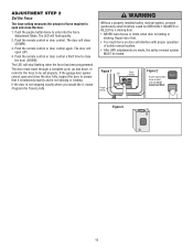
...NOTICE 15 ADJUSTMENT STEP 3 Test The Protector System® • Press the single button control station to open the door. • Place the operator carton in an open door falling rapidly and/or unexpectedly. • NEVER use emergency release handle unless doorway is clear of the door. •... (particularly small children) could result in the path of persons and obstructions. ! ONLY use the emergency release to manually open or close operation. NOTE: To prevent damage to the motor assembly, NEVER use emergency release handle to toggle or stop a falling door. To prevent possible...
...NOTICE 15 ADJUSTMENT STEP 3 Test The Protector System® • Press the single button control station to open the door. • Place the operator carton in an open door falling rapidly and/or unexpectedly. • NEVER use emergency release handle unless doorway is clear of the door. •... (particularly small children) could result in the path of persons and obstructions. ! ONLY use the emergency release to manually open or close operation. NOTE: To prevent damage to the motor assembly, NEVER use emergency release handle to toggle or stop a falling door. To prevent possible...

3950 Manual
Page 16
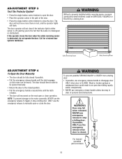
... while closing , the door will close when the beam is unbalanced or binding, call a trained door systems technician. • Check to operate or play with door control push buttons or remote controls. 3. Adjust limits and/or force if necessary (see page 3). Weak or broken ... door could result in a partially open , the door will close. ALWAYS KEEP DOOR PROPERLY BALANCED (see Adjustment Steps 1 and 2). • The operator does not require additional lubrication. ALL repairs to move. Care of SEVERE INJURY or DEATH: 1. If it will reverse. 3. Door MUST reverse on...
... while closing , the door will close when the beam is unbalanced or binding, call a trained door systems technician. • Check to operate or play with door control push buttons or remote controls. 3. Adjust limits and/or force if necessary (see page 3). Weak or broken ... door could result in a partially open , the door will close. ALWAYS KEEP DOOR PROPERLY BALANCED (see Adjustment Steps 1 and 2). • The operator does not require additional lubrication. ALL repairs to move. Care of SEVERE INJURY or DEATH: 1. If it will reverse. 3. Door MUST reverse on...


