3900PLD Manual
Page 2
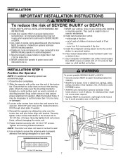
...injury or death if you do not comply with the warnings that accompany it is installed, operated, maintained and tested in strict accordance with the instructions and warnings contained in this Signal Word on the following pages, they will alert you...mounting bracket to the operator 6 Installation 7-16 Installation safety instructions 7 Position the operator 7 Attach the emergency release rope and handle 8 Install power door lock (Not Provided 8 Attach the cable tension monitor (Required 9 Install the single button control station 10 Install the light (Not Provided 11 Electrical...
...injury or death if you do not comply with the warnings that accompany it is installed, operated, maintained and tested in strict accordance with the instructions and warnings contained in this Signal Word on the following pages, they will alert you...mounting bracket to the operator 6 Installation 7-16 Installation safety instructions 7 Position the operator 7 Attach the emergency release rope and handle 8 Install power door lock (Not Provided 8 Attach the cable tension monitor (Required 9 Install the single button control station 10 Install the light (Not Provided 11 Electrical...
3900PLD Manual
Page 4
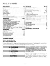
...Torque Meter (not shown) Adjustable End Wrench Needle Nose Pliers 4 To prevent damage to door and operator: • ALWAYS disable locks BEFORE installing and operating the operator. • ONLY operate door operator at 120V, 60 Hz to avoid entanglement. If balanced, it should remain equal ...during the entire travel of the operator, instructions will call for hand tools as shown. To prevent possible SERIOUS INJURY or DEATH: • ALWAYS call a trained door systems technician. 3....
...Torque Meter (not shown) Adjustable End Wrench Needle Nose Pliers 4 To prevent damage to door and operator: • ALWAYS disable locks BEFORE installing and operating the operator. • ONLY operate door operator at 120V, 60 Hz to avoid entanglement. If balanced, it should remain equal ...during the entire travel of the operator, instructions will call for hand tools as shown. To prevent possible SERIOUS INJURY or DEATH: • ALWAYS call a trained door systems technician. 3....
3900PLD Manual
Page 6
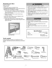
...attach slotted side of mounting bracket to the same side of torque) (Figure 2). ASSEMBLY STEP 1 Attach the Collar to the Operator To avoid installation difficulties, do not run the door operator until instructed to do so. • Loosen the collar screws. • Attach collar to either the left side... installation. Do not tighten set screws until instructed. NOTE: Do not tighten until indicated. Illustrations shown are facing up for left or the right side of collar screws equally to...
...attach slotted side of mounting bracket to the same side of torque) (Figure 2). ASSEMBLY STEP 1 Attach the Collar to the Operator To avoid installation difficulties, do not run the door operator until instructed to do so. • Loosen the collar screws. • Attach collar to either the left side... installation. Do not tighten set screws until instructed. NOTE: Do not tighten until indicated. Illustrations shown are facing up for left or the right side of collar screws equally to...
3900PLD Manual
Page 7
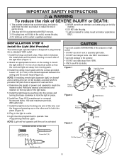
...Disable ALL locks and remove ALL ropes connected to door BEFORE installing operator to prevent antenna from torsion bar and remove the operator. Slide the operator with collar over the torsion bar until instructed to avoid premature wear on properly balanced and lubricated door....sliding the collar over the end of SEVERE INJURY or DEATH: 1. Operator Staple Torsion Bar 14-10x1-7/8" Hex Screw 7 WARNING INSTALLATION IMPORTANT INSTALLATION INSTRUCTIONS WARNING To reduce the risk of the torsion bar. Fasten bracket securely with bracket. NOTE: The motor unit does not have...
...Disable ALL locks and remove ALL ropes connected to door BEFORE installing operator to prevent antenna from torsion bar and remove the operator. Slide the operator with collar over the torsion bar until instructed to avoid premature wear on properly balanced and lubricated door....sliding the collar over the end of SEVERE INJURY or DEATH: 1. Operator Staple Torsion Bar 14-10x1-7/8" Hex Screw 7 WARNING INSTALLATION IMPORTANT INSTALLATION INSTRUCTIONS WARNING To reduce the risk of the torsion bar. Fasten bracket securely with bracket. NOTE: The motor unit does not have...
3900PLD Manual
Page 11
... operator: • DO NOT use bulbs larger than the other end to outlet. 9. No pilot hole is intended for wall anchors. 4. Install two Type A19 incandescent or compact fluorescent bulbs. 100 watt maximum per bulb, 200 watts total. 7. HARDWARE SHOWN ACTUAL SIZE To prevent possible ...of power cord needed to operate. NOTE: Light will fit in place. 6. Install the light lens by pushing onto the screws and turning the base clockwise to plug directly into place (Figure 3). 8. IMPORTANT SAFETY INSTRUCTIONS WARNING To reduce the risk of the light base. 5. Light is required ...
... operator: • DO NOT use bulbs larger than the other end to outlet. 9. No pilot hole is intended for wall anchors. 4. Install two Type A19 incandescent or compact fluorescent bulbs. 100 watt maximum per bulb, 200 watts total. 7. HARDWARE SHOWN ACTUAL SIZE To prevent possible ...of power cord needed to operate. NOTE: Light will fit in place. 6. Install the light lens by pushing onto the screws and turning the base clockwise to plug directly into place (Figure 3). 8. IMPORTANT SAFETY INSTRUCTIONS WARNING To reduce the risk of the light base. 5. Light is required ...

3900PLD Manual
Page 13
... 8 Mount the Standby Power Unit (SPU) (Not Provided) If the optional 475LM Standby Power Unit is part of this installation it should be installed at this time. • The SPU can be mounted to either the ceiling or a wall within 3' (.9 m) of the motor unit. • Position the SPU as ... 1-1/2" lag screws (2) provided with the SPU unit. • Connect the SPU cord into the connector on the bottom of the motor unit. • Follow all instructions included with the 475LM unit to test for proper operation and testing of the SPU.
... 8 Mount the Standby Power Unit (SPU) (Not Provided) If the optional 475LM Standby Power Unit is part of this installation it should be installed at this time. • The SPU can be mounted to either the ceiling or a wall within 3' (.9 m) of the motor unit. • Position the SPU as ... 1-1/2" lag screws (2) provided with the SPU unit. • Connect the SPU cord into the connector on the bottom of the motor unit. • Follow all instructions included with the 475LM unit to test for proper operation and testing of the SPU.
3900PLD Manual
Page 21
...opening , the door will stop . 7. If possible, use emergency release handle unless doorway is activated (with the safety reversing sensor correctly installed and aligned) 1. ALWAYS KEEP DOOR PROPERLY BALANCED (see page 3). When the operator is clear of which are made by a trained ...keep remote controls out of reach of SEVERE INJURY or DEATH: 1. If open . 2. READ AND FOLLOW ALL WARNINGS AND INSTRUCTIONS. 2. WARNING OPERATION IMPORTANT SAFETY INSTRUCTIONS WARNING To reduce the risk of children. ALWAYS keep door in a partially open , the door will blink for five seconds...
...opening , the door will stop . 7. If possible, use emergency release handle unless doorway is activated (with the safety reversing sensor correctly installed and aligned) 1. ALWAYS KEEP DOOR PROPERLY BALANCED (see page 3). When the operator is clear of which are made by a trained ...keep remote controls out of reach of SEVERE INJURY or DEATH: 1. If open . 2. READ AND FOLLOW ALL WARNINGS AND INSTRUCTIONS. 2. WARNING OPERATION IMPORTANT SAFETY INSTRUCTIONS WARNING To reduce the risk of children. ALWAYS keep door in a partially open , the door will blink for five seconds...
3900PLD Manual
Page 23
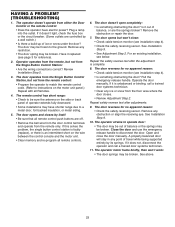
...the door control terminals and operate from the remote control: • Program the operator to match the remote control code. (Refer to instructions on the wire between the control console and the motor unit. • Clear memory and re-program all remote control push buttons ...reverses for no apparent reason: • Check cable tension monitor (see page 3 for no apparent reason: • Check the safety reversing sensor. See Installation Step 9. 10. Close the door and use the emergency release handle to a metal door, foil backed insulation, or metal siding. 5. The door opens ...
...the door control terminals and operate from the remote control: • Program the operator to match the remote control code. (Refer to instructions on the wire between the control console and the motor unit. • Clear memory and re-program all remote control push buttons ...reverses for no apparent reason: • Check cable tension monitor (see page 3 for no apparent reason: • Check the safety reversing sensor. See Installation Step 9. 10. Close the door and use the emergency release handle to a metal door, foil backed insulation, or metal siding. 5. The door opens ...
3900PLD Manual
Page 26
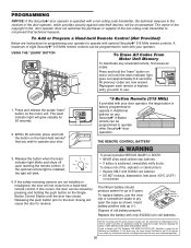
... adjustment or modifications of old battery properly. The learn indicator light goes out (approximately 6-9 seconds). If this receiver and/or transmitter are instructions for 30 seconds. 2. To replace battery, use . 1. Within 30 seconds, press and hold the "learn" button on the Single ...cell batteries. To prevent possible SERIOUS INJURY or DEATH: • NEVER allow small children near batteries. • If battery is installed, the light will blink. 4. Battery positive side up to operate other Security✚® door operators. The owner of the copyright...
... adjustment or modifications of old battery properly. The learn indicator light goes out (approximately 6-9 seconds). If this receiver and/or transmitter are instructions for 30 seconds. 2. To replace battery, use . 1. Within 30 seconds, press and hold the "learn" button on the Single ...cell batteries. To prevent possible SERIOUS INJURY or DEATH: • NEVER allow small children near batteries. • If battery is installed, the light will blink. 4. Battery positive side up to operate other Security✚® door operators. The owner of the copyright...


